2014 FIAT 500X wheel torque
[x] Cancel search: wheel torquePage 157 of 476
Electronic Brake Force Distribution (EBD)
This function manages the distribution of the braking
torque between the front and rear axles by limiting
braking pressure to the rear axle. This is done to prevent
overslip of the rear wheels to avoid vehicle instability,
and to prevent the rear axle from entering ABS before
the front axle.
Brake System Warning Light
The red “Brake System Warning Light” will turn on
when the ignition switch is turned to the ON position
and may stay on for as long as four seconds.
If the “Brake System Warning Light” remains on or
comes on while driving, it indicates that the brake
system is not functioning properly and that immediate
service is required. If the “Brake System Warning Light”
does not come on when the ignition switch is turned to
the ON position, have the light repaired as soon as
possible.
Anti-Lock Brake System (ABS)
The Anti-Lock Brake System (ABS) provides increased
vehicle stability and brake performance under mostbraking conditions. The system automatically prevents
wheel lock, and enhances vehicle control during brak-
ing.
The ABS performs a self-check cycle to ensure that the
ABS is working properly each time the vehicle is started
and driven. During this self-check, you may hear a
slight clicking sound as well as some related motor
noises.
ABS is activated during braking when the system
detects one or more wheels begins to lock. Road condi-
tions such as ice, snow, gravel, bumps, railroad tracks,
loose debris, or panic stops may increase the likelihood
of ABS activation(s).
You also may experience the following when ABS
activates:
•
The ABS motor noise (it may continue to run for a
short time after the stop).
• The clicking sound of solenoid valves.
• Brake pedal pulsations.
•A slight drop of the brake pedal at the end of the stop.
These are all normal characteristics of ABS.
6
SAFETY 155
Page 161 of 476
4. Start the engine.
5. Rotate the steering wheel slightly more than one-halfturn to the left.
6. Push the “ESC Off” button located in the lower switch bank below the climate control four times
within twenty seconds. The “ESC Off Indicator
Light” should turn on and turn off two times.
7. Rotate the steering wheel back to center and then an additional slightly more than one-half turn to the
right.
8. Turn the ignition switch to the OFF position and then back to the ON position. If the sequence was com-
pleted properly, the “ESC Off Indicator Light” will
blink several times to confirm HSA is disabled.
9. Repeat these steps if you want to return this feature to its previous setting.
Traction Control System (TCS)
This system monitors the amount of wheel spin of each
of the driven wheels. If wheel spin is detected, the TCS
may apply brake pressure to the spinning wheel(s)
and/or reduce engine power to provide enhanced
acceleration and stability. A feature of the TCS, Brake Limited Differential (BLD), functions similar to a lim-
ited slip differential and controls the wheel spin across
a driven axle. If one wheel on a driven axle is spinning
faster than the other, the system will apply the brake of
the spinning wheel. This will allow more engine torque
to be applied to the wheel that is not spinning. BLD may
remain enabled even if TCS and ESC are in a reduced
mode.
Electronic Stability Control (ESC)
This system enhances directional control and stability of
the vehicle under various driving conditions. ESC cor-
rects for oversteering or understeering of the vehicle by
applying the brake of the appropriate wheel(s) to assist
in counteracting the oversteer or understeer condition.
Engine power may also be reduced to help the vehicle
maintain the desired path.
ESC uses sensors in the vehicle to determine the vehicle
path intended by the driver and compares it to the
actual path of the vehicle. When the actual path does
not match the intended path, ESC applies the brake of
the appropriate wheel to assist in counteracting the
oversteer or understeer condition.
•
Oversteer - when the vehicle is turning more than
appropriate for the steering wheel position.6
SAFETY 159
Page 163 of 476
WARNING!(Continued)
inflated and unevenly worn tires may also de-
grade ESC performance. Any vehicle modifica-
tion or poor vehicle maintenance that reduces the
effectiveness of the ESC system can increase the
risk of loss of vehicle control, vehicle rollover,
personal injury and death.
Electronic Roll Mitigation (ERM)
This system anticipates the potential for wheel lift by
monitoring the driver ’s steering wheel input and the
speed of the vehicle. When ERM determines that the
rate of change of the steering wheel angle and vehicle’s
speed are sufficient to potentially cause wheel lift, it
then applies the appropriate brake and may also reduce
engine power to lessen the chance that wheel lift will
occur. ERM can only reduce the chance of wheel lift
occurring during severe or evasive driving maneuvers;
it cannot prevent wheel lift due to other factors, such as
road conditions, leaving the roadway, or striking objects
or other vehicles. NOTE:
ERM is disabled anytime the ESC is in “Full
Off” mode (if equipped). Refer to “Electronic Stability
Control (ESC)” in this section for a complete explana-
tion of the available ESC modes.
WARNING!
Many factors, such as vehicle loading, road condi-
tions and driving conditions, influence the chance
that wheel lift or rollover may occur. ERM cannot
prevent all wheel lift or roll overs, especially those
that involve leaving the roadway or striking objects
or other vehicles. The capabilities of an ERM-
equipped vehicle must never be exploited in a
reckless or dangerous manner which could jeopar-
dize the user’s safety or the safety of others.
Dynamic Steering Torque (DST)
Dynamic Steering Torque is a feature of the ESC and
EPS modules that provides torque at the steering wheel
for certain driving conditions in which the ESC module
is detecting vehicle instability. The torque that the
steering wheel receives is only meant to help the driver
realize optimal steering behavior in order to reach/
6
SAFETY 161
Page 164 of 476
maintain vehicle stability. The only notification the
driver receives that the feature is active is the torque
applied to the steering wheel.
NOTE:The DST feature is only meant to help the driver
realize the correct course of action through small
torques on the steering wheel, which means the effec-
tiveness of the DST feature is highly dependent on the
driver ’s sensitivity and overall reaction to the applied
torque. It is very important to realize that this feature
will not steer the vehicle, meaning the driver is still
responsible for steering the vehicle.
OCCUPANT RESTRAINT SYSTEMS
Some of the most important safety features in your
vehicle are the restraint systems:
Occupant Restraint Systems Features
• Seat Belt Systems
• Supplemental Restraint Systems (SRS) Air Bags
• Child Restraints
Some of the safety features described in this section
may be standard equipment on some models, or may be
optional equipment on others. If you are not sure, ask
your authorized dealer.
Important Safety Precautions
Please pay close attention to the information in this
section. It tells you how to use your restraint system
properly, to keep you and your passengers as safe as
possible.
Here are some simple steps you can take to minimize
the risk of harm from a deploying air bag:
1. Children 12 years old and under should always ride buckled up in a vehicle with a rear seat.
2. If a child from 2 to 12 years old (not in a rear-facing child restraint) must ride in the front passenger seat,
move the seat as far back as possible and use the
proper child restraint (refer to “Child Restraints” in
this section for further information).
3. Children that are not big enough to wear the vehicle seat belt properly (refer to “Child Restraints” in this
section for further information) should be secured in
a vehicle with a rear seat in child restraints or
belt-positioning booster seats. Older children who do
not use child restraints or belt-positioning booster
seats should ride properly buckled up in a vehicle
with a rear seat.
162 SAFETY
Page 240 of 476

ALL WHEEL DRIVE (AWD) — IF EQUIPPED
This feature provides on-demand All-Wheel Drive
(AWD). The system is automatic with no driver inputs
or additional driving skills required. Under normal
driving conditions, the front wheels provide most of the
traction. If the front wheels begin to lose traction, power
is shifted automatically to the rear wheels. The greater
the front wheel traction loss, the greater the power
transfer to the rear wheels.
Additionally, on dry pavement under heavy throttle
input (where one may have no wheel spin), torque will
be sent to the rear in a pre-emptive effort to improve
vehicle launch and performance characteristics.
CAUTION!
All wheels must have the same size and type tires.
Unequal tire sizes must not be used. Unequal tire
size may cause failure of the power transfer unit.
DYNAMIC SELECTOR — IF EQUIPPED
The Dynamic Selector combines the capabilities of the
vehicle control systems, along with driver input, to
provide the best performance in all driving conditions.The Dynamic Selector consists of the following posi-
tions:
Auto Mode –
This mode is designed for comfort and
safety in normal driving conditions. In versions
equipped with all-wheel drive, this mode also reduces
fuel consumption by automatically altering the distri-
bution of torque between the front and rear axle.
All Weather Mode – This mode offers increased trac-
tion control and stability control for low traction condi-
tions such as driving on a dirt road or off road as well
as wet and slippery roads.
Dynamic Selector Switch
238 STARTING AND OPERATING
Page 253 of 476

CAUTION!(Continued)
above or below the sensors will not be detected
when they are in close proximity.
• The vehicle must be driven slowly when using
ParkSense in order to be able to stop in time
when an obstacle is detected. It is recommended
that the driver looks over his/her shoulder when
using ParkSense.
If it’s necessary to keep the trailer hitch and hitch ball
assembly mounted for a long period, it is possible to
filter out the trailer hitch and hitch ball assembly
presence in sensor field of view. The filtering operation
must be performed only by an authorized dealer.
LANESENSE — IF EQUIPPED
LaneSense Operation
The LaneSense system is operational at speeds above
37 mph (60 km/h) and below 112 mph (180 km/h). The
LaneSense system uses a forward looking camera to
detect lane markings and measure vehicle position
within the lane boundaries. When both lane markings are detected and the driver
unintentionally drifts out of the lane (no turn signal
applied), the LaneSense system provides a haptic warn-
ing in the form of torque applied to the steering wheel
to prompt the driver to remain within the lane bound-
aries. If the driver continues to unintentionally drift out
of the lane, the LaneSense system provides a visual
warning through the instrument cluster display to
prompt the driver to remain within the lane boundaries.
The driver may manually override the haptic warning
by applying torque into the steering wheel at any time.
When only a single lane marking is detected and the
driver unintentionally drifts across the lane marking
(no turn signal applied), the LaneSense system provides
a visual warning through the instrument cluster display
to prompt the driver to remain within the lane. When
only a single lane marking is detected, a haptic (torque)
warning will not be provided.
NOTE:
When operating conditions have been met, the
LaneSense system will monitor if the driver ’s hands are
on the steering wheel and provides an audible warning
to the driver when the driver ’s hands are not detected
on the steering wheel. The system will cancel if the
driver does not return their hands to the wheel.
7
STARTING AND OPERATING 251
Page 255 of 476
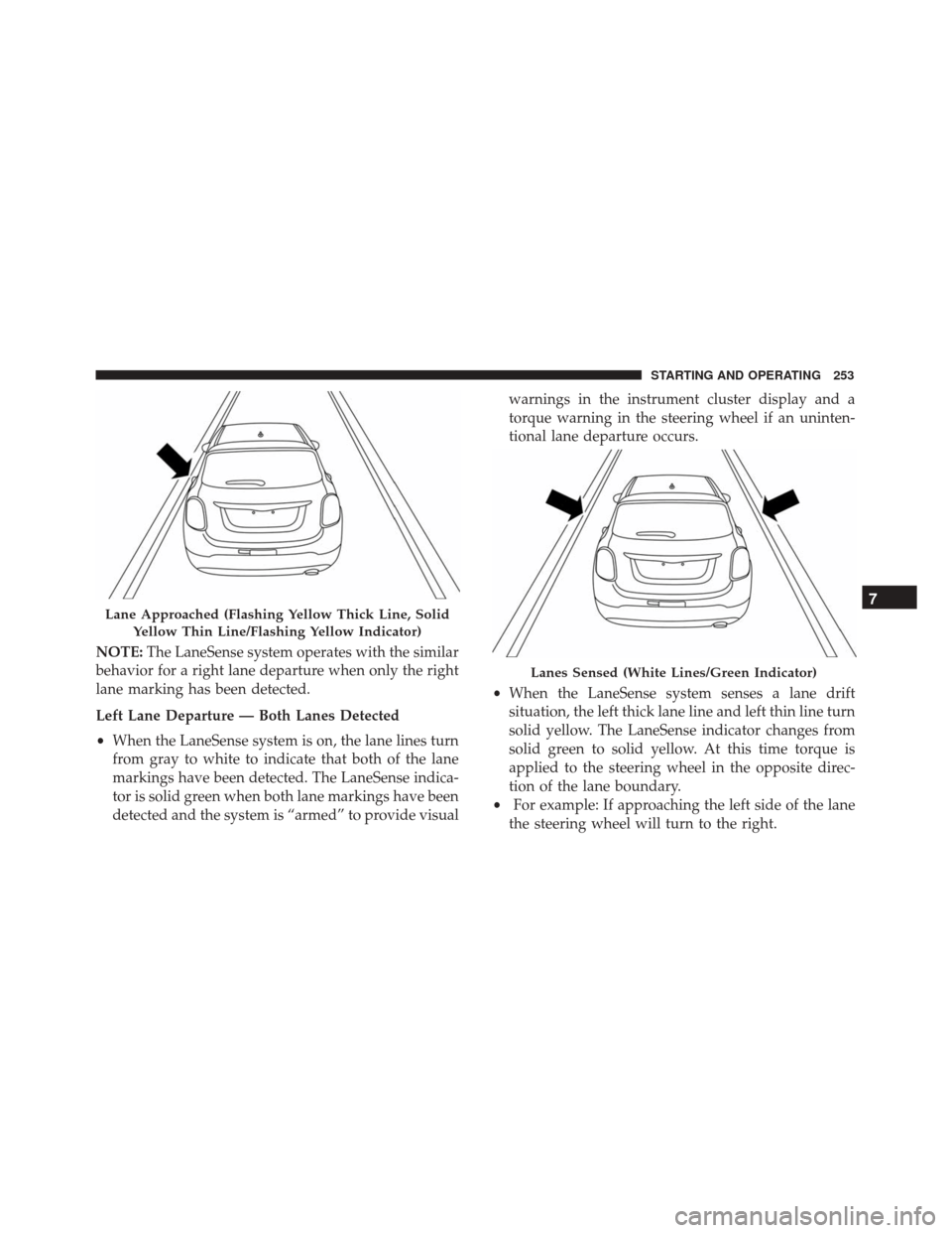
NOTE:The LaneSense system operates with the similar
behavior for a right lane departure when only the right
lane marking has been detected.
Left Lane Departure — Both Lanes Detected
• When the LaneSense system is on, the lane lines turn
from gray to white to indicate that both of the lane
markings have been detected. The LaneSense indica-
tor is solid green when both lane markings have been
detected and the system is “armed” to provide visual warnings in the instrument cluster display and a
torque warning in the steering wheel if an uninten-
tional lane departure occurs.
• When the LaneSense system senses a lane drift
situation, the left thick lane line and left thin line turn
solid yellow. The LaneSense indicator changes from
solid green to solid yellow. At this time torque is
applied to the steering wheel in the opposite direc-
tion of the lane boundary.
• For example: If approaching the left side of the lane
the steering wheel will turn to the right.
Lane Approached (Flashing Yellow Thick Line, Solid
Yellow Thin Line/Flashing Yellow Indicator)
Lanes Sensed (White Lines/Green Indicator)
7
STARTING AND OPERATING 253
Page 256 of 476
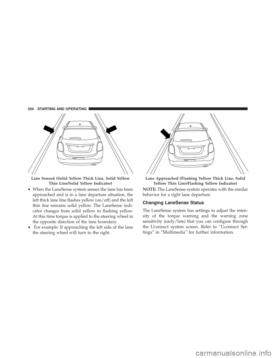
•When the LaneSense system senses the lane has been
approached and is in a lane departure situation, the
left thick lane line flashes yellow (on/off) and the left
thin line remains solid yellow. The LaneSense indi-
cator changes from solid yellow to flashing yellow.
At this time torque is applied to the steering wheel in
the opposite direction of the lane boundary.
• For example: If approaching the left side of the lane
the steering wheel will turn to the right. NOTE:
The LaneSense system operates with the similar
behavior for a right lane departure.
Changing LaneSense Status
The LaneSense system has settings to adjust the inten-
sity of the torque warning and the warning zone
sensitivity (early/late) that you can configure through
the Uconnect system screen. Refer to “Uconnect Set-
tings” in “Multimedia” for further information.
Lane Sensed (Solid Yellow Thick Line, Solid Yellow
Thin Line/Solid Yellow Indicator)Lane Approached (Flashing Yellow Thick Line, SolidYellow Thin Line/Flashing Yellow Indicator)
254 STARTING AND OPERATING