2014 FIAT 500L radio
[x] Cancel search: radioPage 63 of 116

While In: Voice Command Example:
PHONE
Call Initiation(Requires that phone has
been Bluetooth® paired with radio)“Dial 123-456-7890” (phone number)
“Call John Smith mobile” (home, office,
other)
“Redial”
“Show outgoing” (recent) “calls”
Call Management“Search for John Smith” (any contact name
in address book)
“Show (display list) contacts”
Voice Text Reply(Radio audibly recognizes
these 18 pre-formatted SMS messages as
you speak)Forward one of 18 pre-formatted SMS
messages to incoming calls/text messages:
“Yes.”
“No.”
“Okay.”
“I can’t talk right now.”
“Call me.”
“I’ll call you later.”
“I’m on my way.”
“Thanks.”
“I’ll be late.”
“I will be
“See you in
“Stuck in traffic.”
“Start without me.”
“Where are you?”
“Are you there yet?”
“I need directions.”
“I’m lost.”
“See you later.”
ELECTRONICS
61
Page 64 of 116

STEERING WHEEL AUDIO CONTROLS
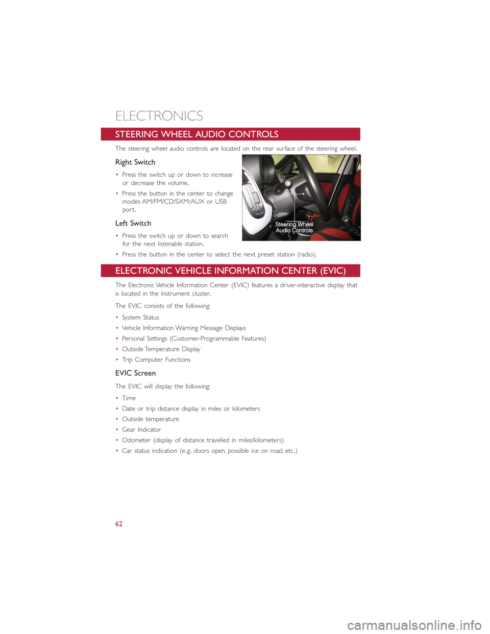
The steering wheel audio controls are located on the rear surface of the steering wheel.
Right Switch
•Press the switch up or down to increase
or decrease the volume.
•Press the button in the center to change
modes AM/FM/CD/SXM/AUX or USB
port.
Left Switch
•Press the switch up or down to search
for the next listenable station.
•Press the button in the center to select the next preset station (radio).
ELECTRONIC VEHICLE INFORMATION CENTER (EVIC)
The Electronic Vehicle Information Center (EVIC) features a driver-interactive display that
is located in the instrument cluster.
The EVIC consists of the following:
•System Status
•Vehicle Information Warning Message Displays
•Personal Settings (Customer-Programmable Features)
•Outside Temperature Display
•Trip Computer Functions
EVIC Screen
The EVIC will display the following:
•Time
•Date or trip distance display in miles or kilometers
•Outside temperature
•Gear Indicator
•Odometer (display of distance travelled in miles/kilometers)
•Car status indication (e.g.doors open, possible ice on road, etc.)
ELECTRONICS
62
Page 65 of 116

EVIC Control Buttons
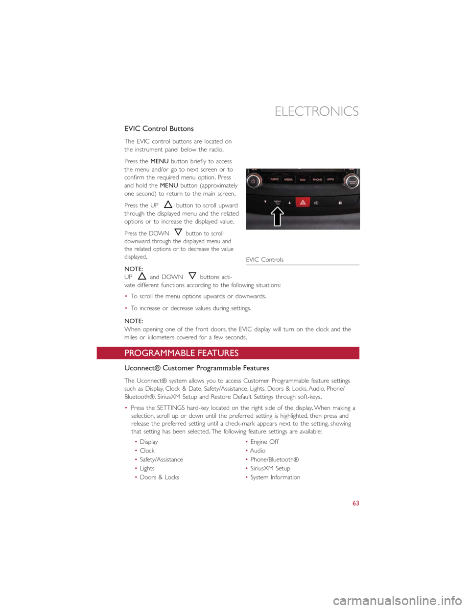
The EVIC control buttons are located on
the instrument panel below the radio.
Press theMENUbutton briefly to access
the menu and/or go to next screen or to
confirm the required menu option.Press
and hold theMENUbutton (approximately
one second) to return to the main screen.
Press the UP
button to scroll upward
through the displayed menu and the related
options or to increase the displayed value.
Press the DOWNbutton to scroll
downward through the displayed menu and
the related options or to decrease the value
displayed.
NOTE:
UP
and DOWNbuttons acti-
vate different functions according to the following situations:
•To scroll the menu options upwards or downwards.
•To increase or decrease values during settings.
NOTE:
When opening one of the front doors, the EVIC display will turn on the clock and the
miles or kilometers covered for a few seconds.
PROGRAMMABLE FEATURES
Uconnect® Customer Programmable Features
The Uconnect® system allows you to access Customer Programmable feature settings
such as Display, Clock & Date, Safety/Assistance, Lights, Doors & Locks, Audio, Phone/
Bluetooth®, SiriusXM Setup and Restore Default Settings through soft-keys.
•Press the SETTINGS hard-key located on the right side of the display.When making a
selection, scroll up or down until the preferred setting is highlighted, then press and
release the preferred setting until a check-mark appears next to the setting, showing
that setting has been selected.The following feature settings are available:
•Display•Engine Off
•Clock•Audio
•Safety/Assistance•Phone/Bluetooth®
•Lights•SiriusXM Setup
•Doors & Locks•System Information
EVIC Controls
ELECTRONICS
63
Page 66 of 116

UNIVERSAL GARAGE DOOR OPENER (HomeLink®)
•HomeLink® replaces up to three hand-held transmitters that operate devices such as
garage door openers, motorized gates, lighting or home security systems.The HomeLink®
unit is powered by your vehicles 12 Volt battery.
•The HomeLink® buttons that are located in the sunvisor designate the three different
HomeLink® channels.
•The HomeLink® indicator is located above the center button.
Before You Begin Programming HomeLink®
Ensure that your vehicle is parked outside of the garage before you begin programming.
For efficient programming and accurate transmission of the radio-frequency signal, it is
recommended that a new battery be placed in the hand-held transmitter of the device
that is being programmed to the HomeLink® system.
Erase all channels before you begin programming.To erase the channels, place the ignition
switch into the ON/RUN position, then press and hold the two outside HomeLink®
buttons (I and III) for up to 20 seconds or until the red indicator flashes.
NOTE:
Erasing all channels should only be performed when programming HomeLink® for the
first time.Do not erase channels when programming additional buttons.
If you have any problems, or require assistance, please call toll-free 1-800-355-3515 or,
on the Internet at www.HomeLink.com for information or assistance.
Programming A Rolling Code
NOTE:
For programming Garage Door Openers that were manufactured after 1995.These
Garage Door Openers can be identified by the “LEARN” or “TRAIN” button located
where the hanging antenna is attached to the Garage Door Opener.It is NOT the but-
ton that is normally used to open and close the door.The name and color of the button
may vary by manufacturer.
1.Place the ignition switch into the ON/RUN position.
2.Place the hand-held transmitter 1 to 3 in (3 to 8 cm) away from the HomeLink®
button you wish to program while keeping the HomeLink® indicator light in view.
3.Simultaneously press and hold both the HomeLink® button you want to program and
the hand-held transmitter button.
4.Continue to hold both buttons and observe the indicator light.The HomeLink® indi-
cator will flash slowly and then rapidly after HomeLink® has received the frequency
signal from the hand-held transmitter.Release both buttons after the indicator light
changes from slow to rapid.
ELECTRONICS
64
Page 89 of 116

Preparations For Jump-Start
•The battery in your vehicle is located on the left side of the engine compartment.
1.Set the parking brake, shift the Euro
Twin Clutch Transmission into PARK and
turn the ignition to OFF/LOCK.
2.Turn off the heater, radio, and all unnec-
essary electrical accessories.
3.If using another vehicle to jump-start
the battery, park the vehicle within the
jumper cables reach, set the parking
brake and make sure the ignition is OFF.
Jump-Starting Procedure
NOTE:
Before connecting the jumper cables to the discharged battery, the negative(-)battery
cable must be disconnected from the discharged battery.This is the only way to success-
fully jump start the vehicle.
Follow these steps to disconnect the negative(-)battery cable:
1.Pull outward on the negative(-)battery cable terminal release lever to the open posi-
tion.
2.Lift up on the negative(-)battery cable terminal and set aside.
•Connecting The Jumper Cables
1.Connect the positive(+)end of the jumper cable to the positive(+)post of the ve-
hicle with the discharged battery.
2.Connect the opposite end of the positive(+)jumper cable to the positive(+)post of
the booster battery.
3.Connect the negative(-)end of the jumper cable to the negative(-)post of the
booster battery.
4.Connect the opposite end of the negative(-)jumper cable to the negative(-)battery
cable terminal of the vehicle with the discharged battery.
1 — Positive Terminal
2 — Negative Terminal
WHAT TO DO IN EMERGENCIES
87
Page 103 of 116

Cavity Maxi Fuse Mini Fuse Description
F21 15 Amp Blue Fuel Pump
F23 20 Amp Yellow Anti-Lock Brake Valves
F24 7.5 Amp Brown Stability Control System
F30 5 Amp Tan After Run Pump
F81 70 Amp Tan PTC (Secondary)
F82 40 Amp Orange Transmission
F83 40 Amp Orange PTC (Primary)
F84 7.5 Amp Brown Transmission
F85 15 Amp Blue Front Power Outlet 12V
F86 15 Amp Blue Rear Power Outlet 12V
F88 7.5 Amp Brown Heated Mirrors
Interior Fuses
•The interior fuse panel is part of the Body Control Module (BCM) and is located on
the driver's side under the instrument panel.
CavityVehicle Fuse
NumberMini Fuse Description
1 F12 7.5 Amp Brown Right Low Beam
2 F32 7.5 Amp BrownFront and Rear Ceiling Lights Trunk
and Door Courtesy Lights
3 F53 7.5 Amp Brown Instrument Panel Node
4 F38 20 Amp Yellow Central Door Locking
5 F36 15 Amp BlueDiagnostic Socket, Car Radio, Climate
Control System, TPMS, Sunroof
6 F43 20 Amp Yellow Bi-Directional Washer
7 F48 20 Amp Yellow Passenger Power Window
MAINTAINING YOUR VEHICLE
101
Page 104 of 116

CavityVehicle Fuse
NumberMini Fuse Description
8 F13 7.5 Amp Brown Left Low Beam, Headlamp Leveling
9 F50 7.5 Amp Brown Airbag
10 F51 5 Amp TanCar Radio Switch, Climate Control
System, Stop Light, Clutch, Reverse
Gear, Sunroof, Parking Sensor, Rear
Camera
11 F37 7.5 Amp BrownStop Light Switch, Instrument Panel
Node
12 F49 5 Amp TanExterior Mirror, GPS, Electric Mirror,
Parking Sensor
13 F31 5 Amp Tan Climate Control, Seat Regulation
14 F47 20 Amp Yellow Driver Power Window
Rear Interior Fuses
•The rear interior fuse panel is located on the driver's side in the rear compartment.
CavityVehicle Fuse
NumberMini Fuse Description
1 F61 15 Amp Blue Lumbar Regulation Seats
2 F62 15 Amp Blue Heated Seats
3 F64 20 Amp Yellow Hi Fi System
4 F65 20 Amp Yellow Sun Blind
5 F66 20 Amp Yellow Sunroof
6 F90 7.5 Amp Brown Left High Beam
7 F91 7.5 Amp Brown Right High Beam
8 F92 7.5 Amp Brown Left Fog Light
9 F93 7.5 Amp Brown Right Fog Light
10 F33 5 Amp Tan BSM, ESP
11 F34 20 Amp Yellow Rear Left Passenger Window
12 F49 20 Amp Yellow Rear Right Passenger Window
MAINTAINING YOUR VEHICLE
102
Page 107 of 116

FIAT CUSTOMER CENTER
P.O.Box 21–8004 Auburn Hills, MI 48321–8004 Phone: 1-888-242-6342
FIAT CANADA CUSTOMER CENTER
P.O.Box 1621 Windsor, Ontario N9A 4H6 Phone: 1–800–465–2001 (English)
Phone: 1–800–387–9983 (French)
ASSISTANCE FOR THE HEARING IMPAIRED
To assist customers who have hearing difficulties, the manufacturer has installed special
TDD (Telecommunication Devices for the Deaf ) equipment at its customer center.Any
hearing or speech impaired customer, who has access to a TDD or a conventional tele-
typewriter (TTY) in the United States, can communicate with the manufacturer by dialing
1–800–380–CHRY.Canadian residents with hearing difficulties that require assistance can
use the special needs relay service offered by Bell Canada.For TTY teletypewriter users,
dial 711 and for Voice callers, dial 1–800–855–0511 to connect with a Bell Relay Service
operator.
WARNING!
Engine exhaust, some of its constituents, and certain vehicle components contain, or
emit, chemicals known to the State of California to cause cancer and birth defects, or
other reproductive harm.In addition, certain fluids contained in vehicles and certain
products of component wear contain, or emit, chemicals known to the State of
California to cause cancer and birth defects, or other reproductive harm.
PUBLICATIONS ORDERING
•If you are the first registered retail owner of your vehicle,you may obtain one free
printed copy of the Owner's Manual, Warranty Booklet or Radio Manuals on your
DVD by calling 1–888–242–6342 (U.S.) or 1–800–387–1143 (Canada) or by
contacting your authorized dealer.
•Replacement English User Guide kits or DVDs may be purchased by visiting
www.techauthority.com or by calling 1–800–890–4038 (U.S.) or 1–800–387–1143
(Canada).Visa, Master Card, American Express and Discover orders are accepted.
If you prefer mailing your order, please call the above numbers for an order form.
NOTE:
A street address is required when ordering manuals (no P.O.Boxes).
CONSUMER ASSISTANCE
105