Page 489 of 703

WARNING!
•When leaving the vehicle, always remove the Key
Fob from the ignition and lock your vehicle.
• Never leave children alone in a vehicle, or with
access to an unlocked vehicle.
• Allowing children to be in a vehicle unattended is
dangerous for a number of reasons. A child or
others could be seriously or fatally injured. Chil-
dren should be warned not to touch the parking
brake, brake pedal or the shift lever.
• Do not leave the Key Fob in or near the vehicle (or
in a location accessible to children), and do not
leave the ignition of a vehicle equipped with
Keyless Enter-N-Go™ in the ACC or ON/RUN
mode. A child could operate power windows, other
controls, or move the vehicle.
(Continued)
WARNING! (Continued)
•Be sure the parking brake is fully disengaged
before driving; failure to do so can lead to brake
failure and a collision.
• Always fully apply the parking brake when leav-
ing your vehicle, or it may roll and cause damage or
injury. Also be certain to leave the transmission in
PARK. Failure to do so may allow the vehicle to roll
and cause damage or injury.
CAUTION!
If the Brake System Warning Light remains on with
the parking brake released, a brake system malfunc-
tion is indicated. Have the brake system serviced by
an authorized dealer immediately.
5
STARTING AND OPERATING 487
Page 491 of 703

•The Anti-Lock Brake System cannot prevent colli-
sions, including those resulting from excessive
speed in turns, following another vehicle too
closely, or hydroplaning.
• The")
WARNING!(Continued)
•The Anti-Lock Brake System cannot prevent colli-
sions, including those resulting from excessive
speed in turns, following another vehicle too
closely, or hydroplaning.
• The capabilities of an ABS-equipped vehicle must
never be exploited in a reckless or dangerous
manner, which could jeopardize the user ’s safety or
the safety of others.
• The ABS cannot prevent the natural laws of phys-
ics from acting on the vehicle, nor can it increase
braking or steering efficiency beyond that afforded
by the condition of the vehicle brakes and tires or
the traction afforded.
All vehicle wheels and tires must be the same size and
type, and tires must be properly inflated to produce
accurate signals for the computer.
Anti-Lock Brake Warning Light
The “Anti-Lock Brake Warning Light” moni-
tors the anti-lock brake system. The light will
come on when the ignition switch is turned to
the ON position and may stay on for as long as
four seconds.
If the “Anti-Lock Brake Warning Light” remains on or
comes on while driving, it indicates that the anti-lock
portion of the brake system is not functioning and that
service is required. However, the conventional brake
system will continue to operate normally if the “Brake
Warning Light” is not on.
If the “Anti-Lock Brake Warning Light” is on, the brake
system should be serviced as soon as possible to restore
the benefits of anti-lock brakes. If the “Anti-Lock Brake
5
STARTING AND OPERATING 489
Page 492 of 703

Warning Light” does not come on when the ignition
switch is turned to the ON position, have the bulb
repaired as soon as possible.
If both the “Brake Warning Light” and the “Anti-Lock
Brake Warning Light” remain on, the ABS and Electronic
Brake Force Distribution (EBD) systems are not function-
ing. Immediate repair to the ABS system is required.
Consult with your authorized dealer service center as
soon as possible.
ELECTRONIC BRAKE CONTROL SYSTEM
Your vehicle is equipped with an advanced electronic
brake control system that includes the Traction Control
System (TCS), Brake Assist System (BAS) and Electronic
Stability Control (ESC), Trailer Sway Control (TSC), and
Hill Start Assist (HSA). These systems complement the
Anti-Lock Brake System (ABS) by optimizing the vehicle
braking capability during emergency braking maneu-
vers.
Traction Control System (TCS)
The Traction Control System (TCS) monitors the amount
of wheel spin of each of the driven wheels. If wheel spin
is detected, brake pressure is applied to the slipping
wheel(s) and engine power is reduced, to provide en-
hanced acceleration and stability. A feature of the TCS
functions similarly to a limited-slip differential, and
controls the wheel spin across a driven axle. If one wheel
on a driven axle is spinning faster than the other, the
system will apply the brake of the spinning wheel. This
will allow more engine torque to be applied to the wheel
that is not spinning. This feature remains active even if
the ESC is in the “Partial Off” mode.
The “ESC Activation/Malfunction Indicator Light” (in
the instrument cluster) will start to flash as soon as the
tires lose traction and the wheels begin to spin. This
indicates that the TCS is active. If the indicator light
flashes during acceleration, ease up on the accelerator
and apply as little throttle as possible. Be sure to adapt
490 STARTING AND OPERATING
Page 502 of 703
TIRE SAFETY INFORMATION
Tire MarkingsNOTE:
•P (Passenger) - Metric tire sizing is based on U.S.
design standards. P-Metric tires have the letter “P”
molded into the sidewall preceding the size designa-
tion. Example: P215/65R15 95H.
• European-Metric tire sizing is based on European
design standards. Tires designed to this standard have
the tire size molded into the sidewall beginning with
the section width. The letter �P�is absent from this tire
size designation. Example: 215/65R15 96H.
• LT (Light Truck) - Metric tire sizing is based on U.S.
design standards. The size designation for LT-Metric
tires is the same as for P-Metric tires except for the
letters “LT” that are molded into the sidewall preced-
ing the size designation. Example: LT235/85R16.
1 — U.S. DOT Safety Standards
Code (TIN) 4 — Maximum Load
2 — Size Designation 5 — Maximum Pressure
3 — Service Description 6 — Treadwear, Traction and
Temperature Grades
500 STARTING AND OPERATING
Page 504 of 703
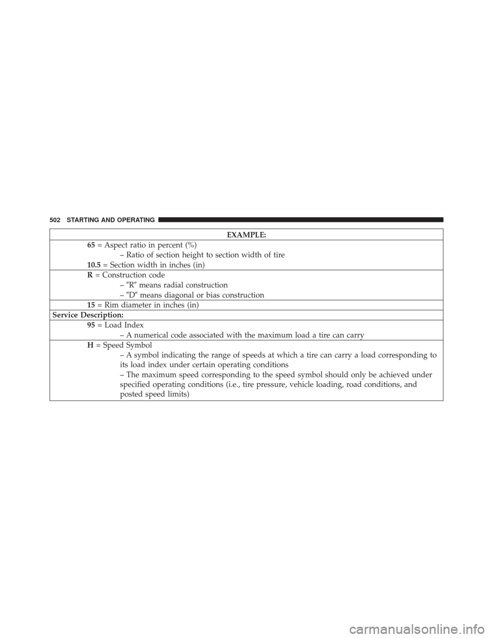
EXAMPLE:
65 = Aspect ratio in percent (%)
– Ratio of section height to section width of tire
10.5 = Section width in inches (in)
R = Construction code
–�R� means radial construction
– �D� means diagonal or bias construction
15 = Rim diameter in inches (in)
Service Description: 95= Load Index
– A numerical code associated with the maximum load a tire can carry
H = Speed Symbol
– A symbol indicating the range of speeds at which a tire can carry a load corresponding to
its load index under certain operating conditions
– The maximum speed corresponding to the speed symbol should only be achieved under
specified operating conditions (i.e., tire pressure, vehicle loading, road conditions, and
posted speed limits)
502 STARTING AND OPERATING
Page 516 of 703

Consult an authorized tire dealer for tire repairs and
additional information.
Damaged Run Flat tires, or Run Flat tires that have
experienced a loss of pressure should be replaced imme-
diately with another Run Flat tire of identical size and
service description (Load Index and Speed Code).
Tire Types
All Season Tires — If Equipped
All Season tires provide traction for all seasons (spring,
summer, fall and winter). Traction levels may vary be-
tween different all season tires. All season tires can be
identified by the M+S, M&S, M/S or MS designation on
the tire sidewall. Use all season tires only in sets of four;
failure to do so may adversely affect the safety and
handling of your vehicle.
Summer Or Three Season Tires — If Equipped
Summer tires provide traction in both wet and dry
conditions, and are not intended to be driven in snow or
on ice. If your vehicle is equipped with summer tires, be
aware these tires are not designed for winter or cold
driving conditions. For more information, contact a au-
thorized dealer. Summer tires do not contain the all
season designation or mountain/snowflake symbol on
the tire sidewall.
Use summer tires only in sets of four; failure to do so may
adversely affect the safety and handling of your vehicle.
Snow Tires
Some areas of the country require the use of snow tires
during the winter. Snow tires can be identified by a
mountain/snowflake symbol on the tire sidewall.
514 STARTING AND OPERATING
Page 521 of 703
Tread Wear Indicators
Tread wear indicators are in the original equipment tires
to help you in determining when your tires should be
replaced.These indicators are molded into the bottom of the tread
grooves. They will appear as bands when the tread depth
becomes 1/16 in (2 mm). When the tread is worn to the
tread wear indicators, the tire should be replaced. Refer
to “Replacement Tires” in this section for further infor-
mation.
Life Of Tire
The service life of a tire is dependent upon varying
factors including, but not limited to:
•
Driving style
• Tire pressure
• Distance driven
• Performance tires, tires with a speed rating of V or
higher, and summer tires typically have a reduced
tread life. Rotation of these tires per the vehicle main-
tenance schedule is highly recommended.
1—WornTire
2—NewTire
5
STARTING AND OPERATING 519
Page 532 of 703

TPMS Low Pressure Warnings
The “Tire Pressure Monitoring Telltale Light” will illumi-
nate in the instrument cluster, and an audible chime will
be activated when one or more of the four active road tire
pressures are low. In addition, the EVIC will display a
“LOW TIRE” message and a graphic display of the
pressure value(s) with the low tire(s) flashing. An�Inflate
Tire to XX� message will also be displayed.
Should a low tire condition occur on any of the four
active road tire(s), you should stop as soon as possible,
and inflate the low tire(s) that is flashing on the graphic
display to the vehicle’s recommended cold tire pressure
value as shown in the �Inflate Tire to XX�message. The
system will automatically update, the graphic display of
the pressure value(s) will stop flashing, and the “Tire
Pressure Monitoring Telltale Light” will extinguish once
the updated tire pressure(s) have been received. NOTE:
The vehicle may need to be driven for up to 20
minutes above 15 mph (24 km/h) to receive this infor-
mation.
SERVICE TPM SYSTEM Message
The “Tire Pressure Monitoring Telltale Light” will flash
on and off for 75 seconds, and remain on solid when a
system fault is detected. The system fault will also sound
a chime. The EVIC will display a “SERVICE TPM SYS-
TEM” message for a minimum of five seconds. This
message is then followed by a graphic display, with --in
place of the pressure value(s) indicating which TPMS
Sensor(s) is not being received.
If the ignition switch is cycled, this sequence will repeat,
providing the system fault still exists. If the system fault
no longer exists, the “Tire Pressure Monitoring Telltale
Light” will no longer flash, the “SERVICE TPM SYSTEM”
530 STARTING AND OPERATING
 - Metric tire sizing is based on U.S.
design standards. P-Metric tires have the letter “P”
molded into the sidewall preceding the size d")