2014 BMW X5 XDRIVE35D park assist
[x] Cancel search: park assistPage 131 of 265

Driving stability control systemsVehicle equipmentAll standard, country-specific and optional
equipment that is offered in the model series is
described in this chapter. Therefore, equip‐
ment is also described that is not available in a
vehicle, e. g., because of the selected optional
equipment or country variant. This also applies
for safety-related functions and systems.
Antilock Brake System ABS ABS prevents locking of the wheels during
braking.
The vehicle remains steerable even during full
brake applications, thus increasing active
safety.
ABS is operational every time you start the en‐
gine.
Brake assistant
When you apply the brakes rapidly, this system
automatically produces the maximum braking
force boost. This then reduces braking dis‐ tance to a minimum during full braking. This
system utilizes all of the benefits provided by ABS.
Do not reduce the pressure on the brake pedal
for the duration of the full braking.
When equipped with Driving Assistant Plus or
with Active Cruise Control with Stop & Go
function, ACC is supported by the braking in‐
tervention if there is a possible risk of collision.
To do this, the braking force is automatically increased if the braking pressure is insufficient
when the brakes are applied.Drive-off assistant
This system supports driving away on gradi‐
ents. The parking brake is not required.1.Hold the vehicle in place with the foot
brake.2.Release the foot brake and drive away
without delay.
After the foot brake is released, the vehicle is
held in place for approx. 2 seconds.
Depending on the vehicle load or when a trailer
is being used, the vehicle may roll back
slightly.
Driving off without delay
After releasing the foot brake, start driv‐
ing without delay, since the drive-off assistant
will not hold the vehicle in place for more than
approx. 2 seconds and the vehicle will begin
rolling back.◀
Automatic Differential Brake
The system controls the driving force by auto‐
matic braking intervention on individual
wheels. The function corresponds to a differ‐
ential lock: the system detects if a wheel be‐
gins to spin, because of loose road surface, for
example, and automatically brakes it.
The driving force is diverted to the wheel with
better traction.
As a result, the engine force is transferred
more efficiently to the wheels during accelera‐
tions.
Seite 131Driving stability control systemsControls131
Online Edition for Part no. 01 40 2 926 740 - X/13
Page 141 of 265

Speed differences
Large differences in speed relative to
other vehicles cannot be compensated by the
system for example in the following situations:▷When catching up rapidly with a truck.▷When another vehicle suddenly swerves
into the wrong lane.▷When stationary objects are approached at
speed.◀
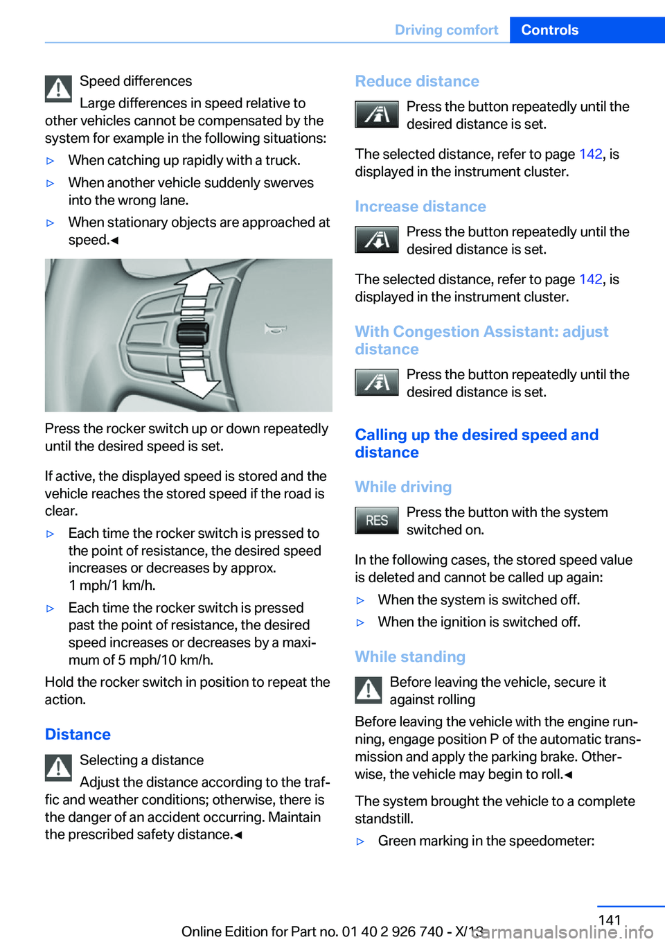
Press the rocker switch up or down repeatedly
until the desired speed is set.
If active, the displayed speed is stored and the
vehicle reaches the stored speed if the road is
clear.
▷Each time the rocker switch is pressed to
the point of resistance, the desired speed
increases or decreases by approx.
1 mph/1 km/h.▷Each time the rocker switch is pressed
past the point of resistance, the desired
speed increases or decreases by a maxi‐
mum of 5 mph/10 km/h.
Hold the rocker switch in position to repeat the
action.
Distance Selecting a distance
Adjust the distance according to the traf‐
fic and weather conditions; otherwise, there is
the danger of an accident occurring. Maintain
the prescribed safety distance.◀
Reduce distance
Press the button repeatedly until the
desired distance is set.
The selected distance, refer to page 142, is
displayed in the instrument cluster.
Increase distance Press the button repeatedly until the
desired distance is set.
The selected distance, refer to page 142, is
displayed in the instrument cluster.
With Congestion Assistant: adjust
distance
Press the button repeatedly until the
desired distance is set.
Calling up the desired speed and distance
While driving Press the button with the system
switched on.
In the following cases, the stored speed value
is deleted and cannot be called up again:▷When the system is switched off.▷When the ignition is switched off.
While standing
Before leaving the vehicle, secure it
against rolling
Before leaving the vehicle with the engine run‐
ning, engage position P of the automatic trans‐
mission and apply the parking brake. Other‐
wise, the vehicle may begin to roll.◀
The system brought the vehicle to a complete
standstill.
▷Green marking in the speedometer:Seite 141Driving comfortControls141
Online Edition for Part no. 01 40 2 926 740 - X/13
Page 153 of 265

▷On uneven surfaces, such as speed
bumps.▷In large buildings with right angles and
smooth walls, e.g., in underground ga‐
rages.▷In heavy exhaust.▷Due to other ultrasound sources, e.g.,
sweeping machines, high pressure steam
cleaners or neon lights.
Malfunction
A Check Control message is displayed.
The range of the sensors is shown as a shaded
area on the Control Display.
PDC has failed. Have the system checked.
To ensure full operability:
▷Keep the sensors clean and free of ice.▷When using high-pressure washers, do not
spray the sensors for long periods and
maintain a distance of at least 12 in/30 cm.
Surround View
The concept Surround View comprises various camera as‐
sistance systems that help the driver when
parking, maneuvering, and at complex exits
and intersections.
▷Rearview camera, refer to page 153▷Top View, refer to page 156.▷Panorama Side View, refer to page 158.
Backup camera
The concept
The rearview camera provides assistance in
parking and maneuvering backwards. The area
behind the vehicle is shown on the Control
Display.
Hints
Check the traffic situation as well
Check the traffic situation around the ve‐
hicle with your own eyes. Otherwise, an acci‐
dent could result from road users or objects lo‐
cated outside the picture area of the backup
camera.◀
At a glance
Button in the vehicle
Rearview camera
Camera
The camera lens is located in the handle of the
tailgate. The image quality may be impaired by
dirt.
Clean the lens, refer to page 247.
Switching on/off
Switching on automatically Select transmission position R with the engine
running.
Seite 153Driving comfortControls153
Online Edition for Part no. 01 40 2 926 740 - X/13
Page 154 of 265

The rearview camera image is displayed if the
system was switched on via the iDrive.
Automatic deactivation during forward
travel
The system switches off when a certain driving
distance or speed is exceeded.
Switch the system back on if necessary.
Switching on/off manually Press the button.▷On: the LED lights up.▷Off: the LED goes out.
The PDC is shown on the Control Display.
Switching on the rearview camera via
the iDrive
With PDC activated or Top View switched on:
"Rear view camera"
The rearview camera image is displayed. The
setting is stored for the remote control cur‐
rently in use.
Display on the Control Display
Functional requirement
▷The rearview camera is switched on.▷The tailgate is fully closed.
Activating the assistance functions
More than one assistance function can be ac‐
tive at the same time.
▷Parking aid lines
"Parking aid lines"
Pathway and turning circle lines are dis‐
played.
▷Obstacle marking
"Obstacle marking"
Spatially-shaped markings are displayed.
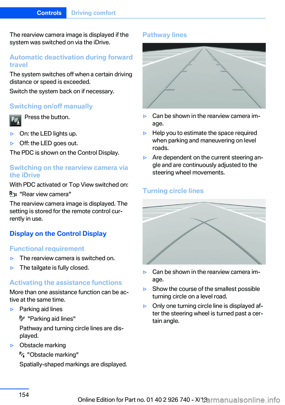
Pathway lines▷Can be shown in the rearview camera im‐
age.▷Help you to estimate the space required
when parking and maneuvering on level
roads.▷Are dependent on the current steering an‐
gle and are continuously adjusted to the
steering wheel movements.
Turning circle lines
▷Can be shown in the rearview camera im‐
age.▷Show the course of the smallest possible
turning circle on a level road.▷Only one turning circle line is displayed af‐
ter the steering wheel is turned past a cer‐
tain angle.Seite 154ControlsDriving comfort154
Online Edition for Part no. 01 40 2 926 740 - X/13
Page 155 of 265

Obstacle marking
General information
Obstacles behind the vehicle are detected by
the PDC sensors and, when appropriately
equipped, detected by the rearview camera.
Marks for detected obstacles can be shown in
the rearview camera image.
Their colored steps match the markings of the
PDC. This simplifies estimation of the distance
to the object shown.
Parking using pathway and turning
circle lines
1.Position the vehicle so that the turning cir‐
cle lines lead to within the limits of the
parking space.2.Turn the steering wheel to the point where
the pathway line covers the corresponding
turning circle line.
Display settings
Brightness
With the rearview camera switched on:
1. Select the symbol.2.Turn the controller until the desired setting
is reached, and press the controller.
Contrast
With the rearview camera switched on:
1. Select the symbol.2.Turn the controller until the desired setting
is reached, and press the controller.
System limits
Detection of objects
Very low obstacles as well as high, protruding
objects such as ledges may not be detected by
the system.
Assistance functions also take into account
data of the PDC.
Follow instructions in the PDC chapter, refer to
page 150.
The objects displayed in the Control Display
under certain circumstances are closer than
they appear. Therefore, do not estimate the
distance from the objects on the display.
Seite 155Driving comfortControls155
Online Edition for Part no. 01 40 2 926 740 - X/13
Page 156 of 265

Top View
The concept Top View provides assistance in parking and
maneuvering. The area around the vehicle is
shown on the Control Display.
General information The image is captured by two cameras
integrated in the exterior mirrors, by the rear‐
view camera and a camera on the front of the
vehicle.
The range is no more than approx. 6.5 ft/2 m to
the side, front and rear.
Obstacles within this range are thus displayed
early on the Control Display.
Notes Check the traffic situation as well
Check the traffic situation around the ve‐
hicle with your own eyes. Otherwise, an acci‐
dent could result from road users or objects lo‐
cated outside the picture area of the
cameras.◀
At a glance
Button in the vehicle
Top View
Cameras
Front camera
The lenses of the Top View cameras are lo‐
cated at the bottom of the exterior mirror hous‐
ings. The image quality may be impaired by
dirt.
Clean the lens, refer to page 247.
Functional requirements
Top View can be used only to a limited extent
in the following situations:
▷With a door open.▷With the tailgate open.▷With an exterior mirror folded in.▷In poor light.
The unavailable camera range is depicted with
cross-hatching.
Switching on/off
Switching on automatically
Select drive mode R with the engine running.
Seite 156ControlsDriving comfort156
Online Edition for Part no. 01 40 2 926 740 - X/13
Page 157 of 265

The Top View and PDC images are displayed if
the system is switched on via iDrive.
Automatic deactivation during forward
travel
The system switches off when a certain driving
distance or speed is exceeded.
Switch the system back on if necessary.
Switching on/off manually Press the button.▷On: the LED lights up.▷Off: the LED goes out.
Top View is displayed.
Switching on the backup camera via
the iDrive
With Top View switched on:
"Rear view camera"
The backup camera image is displayed. The
setting is stored for the remote control cur‐
rently in use.
Display
Display on the Control Display The area surrounding the vehicle can be dis‐
played on the Control Display.
The display appears as soon as Top View is
activated.
If the rearview camera image was selected last,
it again appears on the display when reverse
gear is selected. To switch to Top View:
"Rear view camera" Select the symbol on
the Control Display.
The setting is stored for the remote control
currently in use.
Brightness
With Top View switched on:1. Select the symbol.2.Turn the controller until the desired setting
is reached, and press the controller.
Contrast
With Top View switched on:
1. Select the symbol.2.Turn the controller until the desired setting
is reached, and press the controller.
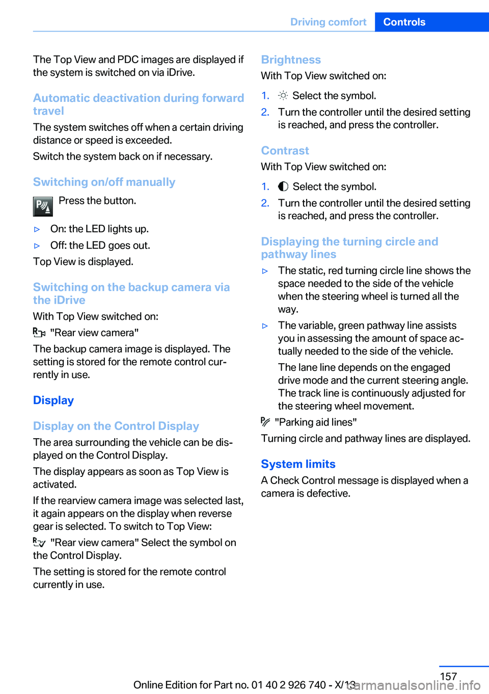
Displaying the turning circle and
pathway lines
▷The static, red turning circle line shows the
space needed to the side of the vehicle
when the steering wheel is turned all the
way.▷The variable, green pathway line assists
you in assessing the amount of space ac‐
tually needed to the side of the vehicle.
The lane line depends on the engaged
drive mode and the current steering angle.
The track line is continuously adjusted for
the steering wheel movement.
"Parking aid lines"
Turning circle and pathway lines are displayed.
System limits
A Check Control message is displayed when a
camera is defective.
Seite 157Driving comfortControls157
Online Edition for Part no. 01 40 2 926 740 - X/13
Page 159 of 265

Switching on/off
Switching on/off manually Press the button.
Depending on the transmission position, the
picture of the front or rear camera is displayed.
Switching off automaticallyBy switching into a different function or during
drive mode change.
Front Panorama Side View: when a certain
driving distance or speed is exceeded.
Display
General information The traffic area in front of or behind the vehicle
is displayed on the Control Display.
Brightness
With Panorama Side View switched on:1. Select the symbol.2.Turn the controller until the desired setting
is reached, and press the controller.
Contrast
With Panorama Side View switched on:
1. Select the symbol.2.Turn the controller until the desired setting
is reached, and press the controller.
Warning of crossing traffic
The concept If an object approaching from the side is de‐
tected by the front or rear camera, this is de‐ picted by a symbol in the Panorama Side View
display.
Requirements
▷Panorama Side View switched on.▷Your vehicle moves no faster than walking
speed.▷To detect approaching objects, sufficient
brightness, for example, daylight is neces‐
sary.
Display
The yellow symbol is displayed if anapproaching vehicle is detected by the
camera.
A gray symbol is displayed if the detec‐
tion of crossing traffic is not possible.
System limits
In the following situations, the warning about
crossing traffic may be limited:
▷In poor lighting or visibility conditions.▷If the camera is soiled or covered.
System limits
The objects displayed in the Control Display
under certain circumstances are closer than
they appear. Therefore, do not estimate the
distance from the objects on the display.
The viewing angle is approx. 180°.
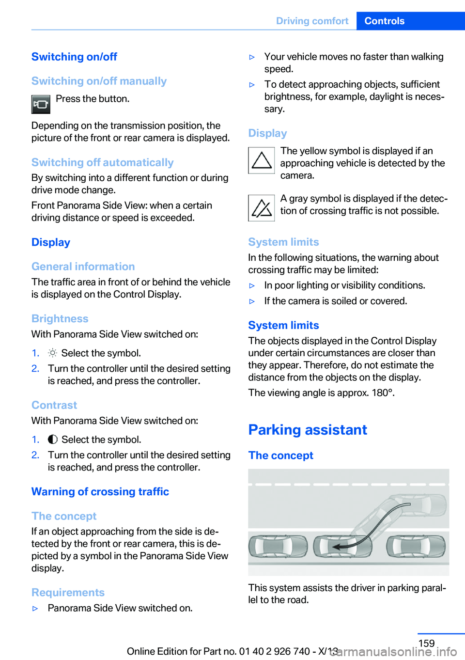
Parking assistantThe concept
This system assists the driver in parking paral‐
lel to the road.
Seite 159Driving comfortControls159
Online Edition for Part no. 01 40 2 926 740 - X/13