2014 BMW X3 XDRIVE 28I ECU
[x] Cancel search: ECUPage 66 of 208
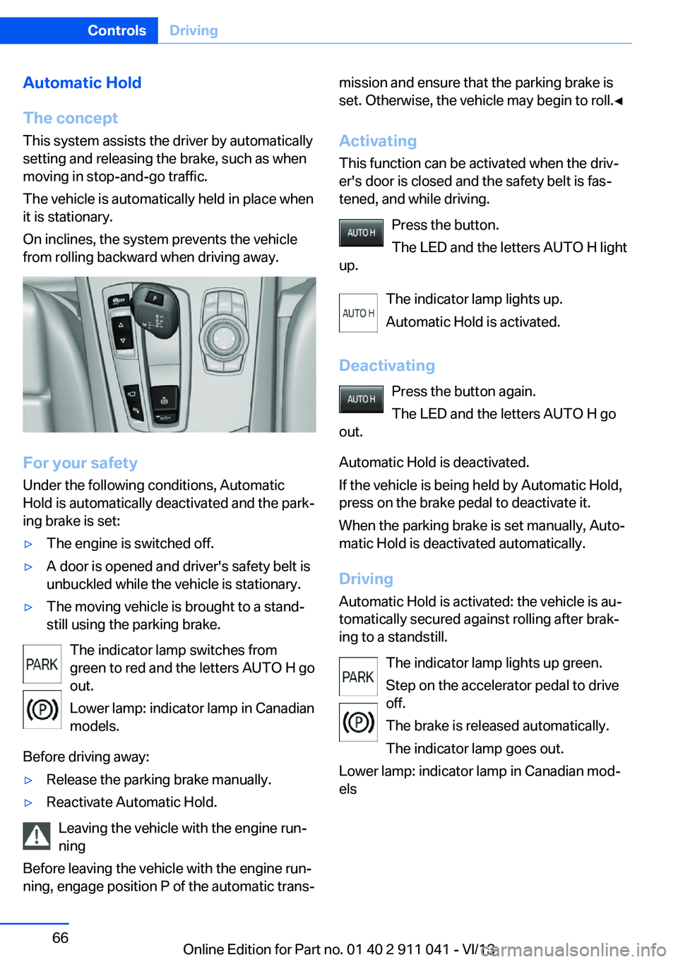
Automatic Hold
The concept This system assists the driver by automatically
setting and releasing the brake, such as when
moving in stop-and-go traffic.
The vehicle is automatically held in place when
it is stationary.
On inclines, the system prevents the vehicle
from rolling backward when driving away.
For your safety
Under the following conditions, Automatic
Hold is automatically deactivated and the park‐
ing brake is set:
▷The engine is switched off.▷A door is opened and driver's safety belt is
unbuckled while the vehicle is stationary.▷The moving vehicle is brought to a stand‐
still using the parking brake.
The indicator lamp switches from
green to red and the letters AUTO H go out.
Lower lamp: indicator lamp in Canadian
models.
Before driving away:
▷Release the parking brake manually.▷Reactivate Automatic Hold.
Leaving the vehicle with the engine run‐
ning
Before leaving the vehicle with the engine run‐
ning, engage position P of the automatic trans‐
mission and ensure that the parking brake is
set. Otherwise, the vehicle may begin to roll.◀
Activating This function can be activated when the driv‐
er's door is closed and the safety belt is fas‐
tened, and while driving.
Press the button.
The LED and the letters AUTO H light
up.
The indicator lamp lights up.
Automatic Hold is activated.
Deactivating Press the button again.
The LED and the letters AUTO H go
out.
Automatic Hold is deactivated.
If the vehicle is being held by Automatic Hold,
press on the brake pedal to deactivate it.
When the parking brake is set manually, Auto‐
matic Hold is deactivated automatically.
Driving Automatic Hold is activated: the vehicle is au‐
tomatically secured against rolling after brak‐
ing to a standstill.
The indicator lamp lights up green.
Step on the accelerator pedal to drive
off.
The brake is released automatically.
The indicator lamp goes out.
Lower lamp: indicator lamp in Canadian mod‐
elsSeite 66ControlsDriving66
Online Edition for Part no. 01 40 2 911 041 - VI/13
Page 67 of 208

Before driving into a car wash
Before driving into the car wash, deacti‐
vate Automatic Hold; otherwise, the parking
brake will be set when the vehicle is stationary
and the vehicle will no longer be able to roll.◀
Parking
The parking brake is automatically set if the
engine is switched off while the vehicle is be‐
ing held by Automatic Hold.
The indicator lamp changes from green
to red.
The parking brake is not set if the en‐
gine is switched off while the vehicle is
coasting to a halt. Automatic Hold is
deactivated.
Lower lamp: indicator lamp in Canadian mod‐
els
Automatic Hold remains activated during the
engine stop brought about by the Auto Start/
Stop function.
Take the remote control with you
Take the remote control with you when
leaving the vehicle so that children, for exam‐
ple, cannot release the parking brake.◀
Malfunction
In the event of a failure or malfunction of the
parking brake, secure the vehicle against roll‐
ing using a wheel chock, for example, when leaving it.Turn signal, high beams,
headlamp flasher
Turn signal
Using turn signals
Press the lever beyond the resistance point.
To switch off manually, press the lever to the
resistance point.
Unusually rapid flashing of the indicator lamp
indicates that a turn signal bulb has failed.
Triple turn signal activation Press the lever to the resistance point.
The turn signal flashes three times.
The function can be activated or deactivated:
1."Settings"2."Lighting"3."Triple turn signal"
Signaling briefly
Press the lever to the resistance point and hold
it there for as long as you want the turn signal
to flash.
Seite 67DrivingControls67
Online Edition for Part no. 01 40 2 911 041 - VI/13
Page 71 of 208
For the capacity, refer to technical data.Automatic transmission with
Steptronic
Transmission positions
D Drive, automatic position
Position for normal vehicle operation. All for‐
ward gears are available.
R is Reverse
Select only when the vehicle is stationary.
N is NeutralUse in automatic car washes, for example. The
vehicle can roll.
When the ignition is switched off, refer to
page 61, position P is engaged automatically.
P Park Select only when the vehicle is stationary. The
drive wheels are blocked.
P is engaged automatically:▷After the engine is switched off when the
vehicle is in radio ready state, refer to
page 62, or when the ignition is switched
off, refer to page 61, and when position R
or D is engaged.▷With the ignition is off, if position N is en‐
gaged.▷If the safety belt is unbuckled, the driver's
door is opened, and the brake pedal is not
pressed while the vehicle is stationary and
transmission position R or D is engaged.
Before exiting the vehicle, make sure that posi‐
tion P of the automatic transmission is en‐
gaged. Otherwise, the vehicle may begin to
roll.
Kickdown
Kickdown is used to achieve maximum driving
performance. Press on the gas pedal beyond
the resistance point at the full throttle position.
Engaging the transmission position▷Transmission position P can only be disen‐
gaged if the engine is running and the
brake pedal is pressed.▷With the vehicle stationary, press on the
brake pedal before shifting out of P or N;
otherwise, the shift command will not be
executed: shift lock.
Depress the brake until you start
driving
To prevent the vehicle from creeping after
you select a driving position, maintain
pressure on the brake pedal until you are
ready to start.◀
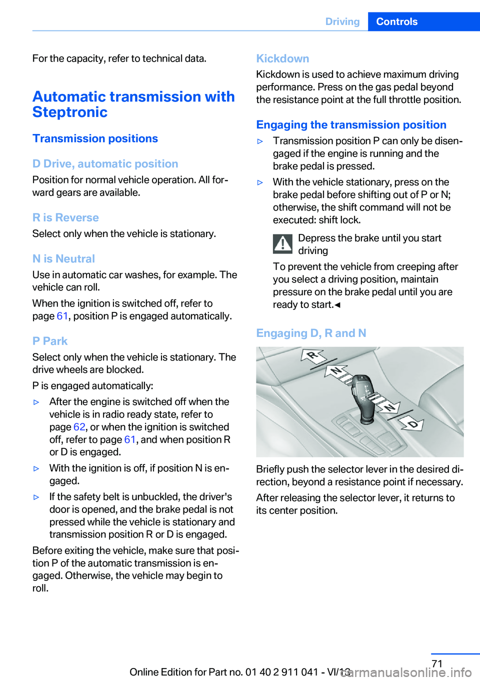
Engaging D, R and N
Briefly push the selector lever in the desired di‐
rection, beyond a resistance point if necessary.
After releasing the selector lever, it returns to
its center position.
Seite 71DrivingControls71
Online Edition for Part no. 01 40 2 911 041 - VI/13
Page 80 of 208

Contact Roadside Assistance.
Hiding Check Control messages
Press the computer button on the turn signal
lever.
▷Some Check Control messages are dis‐
played continuously and are not cleared
until the malfunction is eliminated. If sev‐
eral malfunctions occur at once, the mes‐
sages are displayed consecutively.
These messages can be hidden for approx.
8 seconds. After this time, they are dis‐
played again automatically.▷Other Check Control messages are hidden
automatically after approx. 20 seconds.
They are stored and can be displayed
again later.
Displaying stored Check Control
messages
1."Vehicle Info"2."Vehicle status"3. "Check Control"4.Select the text message.
Messages after trip completion
Special messages that are displayed during
driving are displayed again after the ignition is
switched off.
Fuel gauge
The vehicle inclination may
cause the display to vary.
US models: the arrow beside the
fuel pump symbol shows which
side of the vehicle the fuel filler
flap is on.
Hints on refueling, refer to page 156.
Tachometer
Always avoid engine speeds in the red warning
field. In this range, the fuel supply is inter‐
rupted to protect the engine.
Engine oil temperature▷Cold engine: the pointer is at
the low temperature end.
Drive at moderate engine
and vehicle speeds.▷Normal operating tempera‐
ture: the pointer is in the
middle or in the left half of
the temperature display.▷Hot engine: the pointer is at the high tem‐
perature end. A Check Control message is
also displayed.
Coolant temperature
If the coolant along with the engine becomes
too hot, a Check Control message is displayed.
Check the coolant level, refer to page 171.
Seite 80ControlsDisplays80
Online Edition for Part no. 01 40 2 911 041 - VI/13
Page 131 of 208
Interior equipmentVehicle equipmentAll standard, country-specific and optional
equipment that is offered in the model series is
described in this chapter. Therefore, equip‐
ment is also described that is not available in a
vehicle, e. g., because of the selected optional
equipment or country variant. This also applies
for safety-related functions and systems.
Integrated universal remote
control
The conceptThe integrated universal remote control can
operate up to 3 functions of remote-controlled
systems such as garage door drives or lighting
systems. The integrated universal remote con‐
trol replaces up to 3 different hand-held trans‐
mitters. To operate the remote control, the
buttons on the interior rearview mirror must be
programmed with the desired functions. The
hand-held transmitter for the particular system
is required in order to program the remote con‐
trol.
During programming
During programming and before activat‐
ing a device using the integrated universal re‐
mote control, ensure that there are no people,
animals, or objects in the range of movement
of the remote-controlled device; otherwise,
there is a risk of injury or damage.
Also follow the safety instructions of the hand-
held transmitter.◀
Before selling the vehicle, delete the stored
functions for the sake of security.Compatibility
If this symbol is printed on the packag‐
ing or in the instructions of the system
to be controlled, the system is gener‐
ally compatible with the integrated universal
remote control.
If you have any questions, please contact:▷Your service center.▷www.homelink.com on the Internet.
HomeLink is a registered trademark of John‐
son Controls, Inc.
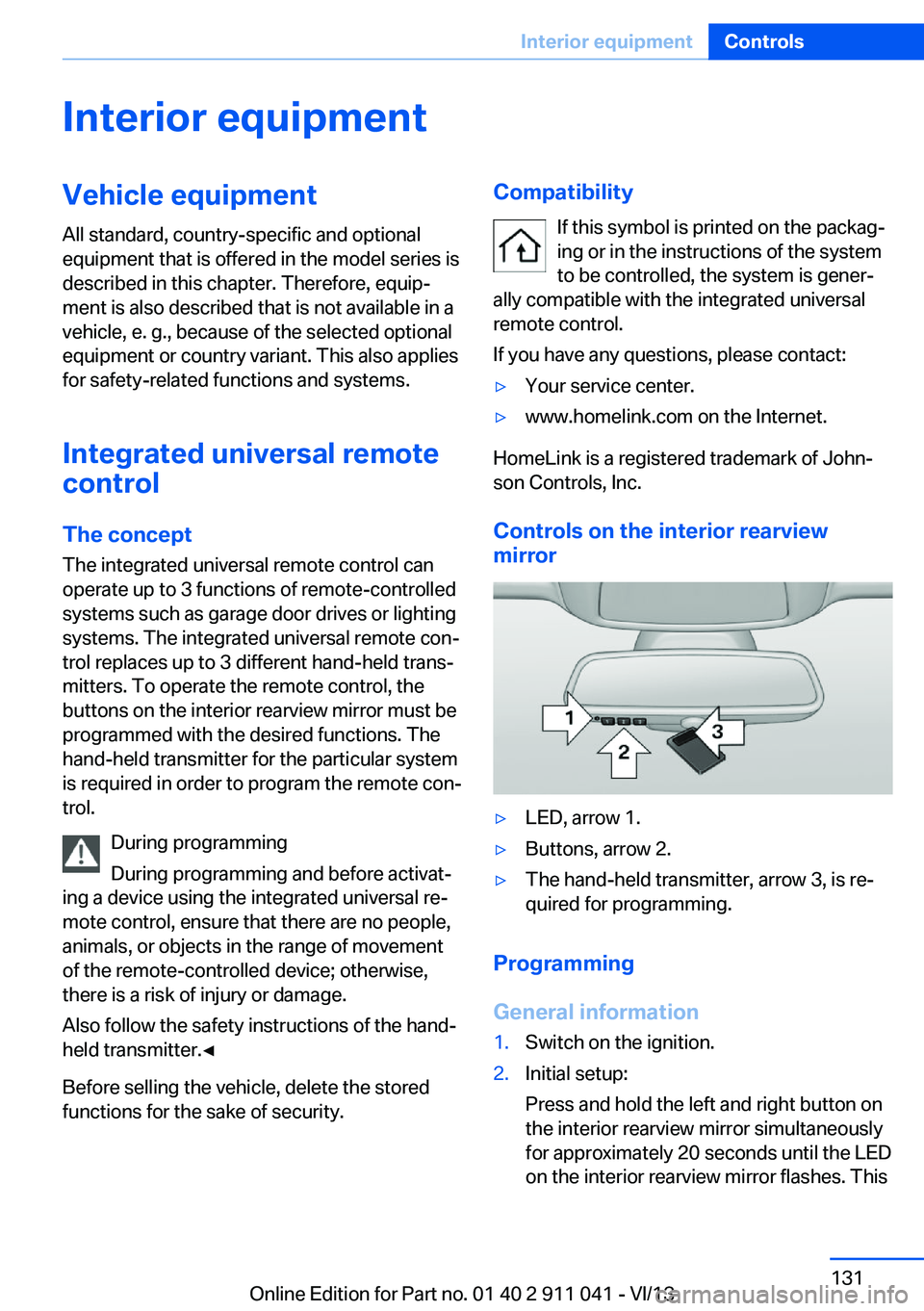
Controls on the interior rearview
mirror
▷LED, arrow 1.▷Buttons, arrow 2.▷The hand-held transmitter, arrow 3, is re‐
quired for programming.
Programming
General information
1.Switch on the ignition.2.Initial setup:
Press and hold the left and right button on
the interior rearview mirror simultaneously
for approximately 20 seconds until the LED
on the interior rearview mirror flashes. ThisSeite 131Interior equipmentControls131
Online Edition for Part no. 01 40 2 911 041 - VI/13
Page 136 of 208
Enlarging the cargo area
General information
The cargo area can be enlarged by folding
down the rear seat backrest.
The rear seat backrest is divided into two parts
at a ratio of 60 to 40.
If equipped with through-loading system: the
rear seat backrest is divided in the ratio 40–20–
40. The sides and the middle section can be
folded down separately.
Hints Danger of pinching
Before folding down the rear seat back‐
rests, ensure that the area of movement of the
backrests is clear. In particular, ensure that no
one is located in the area of movement and
that no one reaches into the area of movement
of the rear seat backrests when the middle
section is folded down. Otherwise, injury or
damage may result.◀
Lock the rear seat backrests in position
Before mounting child restraint fixing
systems, place the seat backrest as far as pos‐
sible at an angle at which the child seat is rest‐
ing firmly against the backrest and all back‐
rests can be locked securely in place.
Otherwise, the child seat will not be as stable
as it should be, and there is increased danger
of injury due to unexpected movement of the
seat backrest.◀
Ensure that the lock is securely engaged
When folding back the backrest, be sure
that it locks in place securely. When this hap‐
pens the red warning field on the seat disap‐
pears. If it is not properly engaged, transported
cargo could enter the passenger compartment
during braking or evasive maneuvers and en‐
danger the vehicle occupants.◀Using the middle safety belt
If the middle safety belt in the rear is
used, the larger section of the backrest must
be locked. Otherwise, the safety belt will not
have a restraining effect.◀
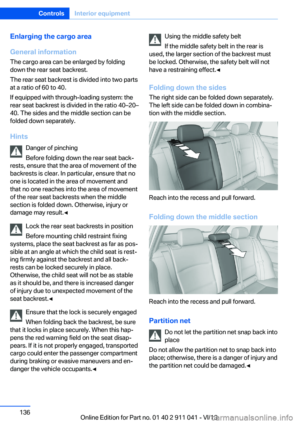
Folding down the sides The right side can be folded down separately.
The left side can be folded down in combina‐
tion with the middle section.
Reach into the recess and pull forward.
Folding down the middle section
Reach into the recess and pull forward.
Partition net Do not let the partition net snap back into
place
Do not allow the partition net to snap back into
place; otherwise, there is a danger of injury and
the partition net could be damaged.◀
Seite 136ControlsInterior equipment136
Online Edition for Part no. 01 40 2 911 041 - VI/13
Page 138 of 208
Storage compartmentsVehicle equipmentAll standard, country-specific and optional
equipment that is offered in the model series is
described in this chapter. Therefore, equip‐
ment is also described that is not available in a
vehicle, e. g., because of the selected optional
equipment or country variant. This also applies
for safety-related functions and systems.
Notes No loose objects in the passenger com‐
partment
Do not stow any objects in the passenger
compartment without securing them; other‐
wise, they may present a danger to occupants
for instance during braking and avoidance ma‐
neuvers.◀
Do not place anti-slip mats on the dash‐
board
Do not place anti-slip mats on the dashboard.
The mat materials could damage the dash‐
board.◀
Storage compartments
The following storage compartments are avail‐
able in the vehicle interior:▷Glove compartment on the front passenger
side, refer to page 138.▷Storage compartment in the front center
armrest, refer to page 139.▷Compartments in the doors.▷Pockets on the backrests of the front
seats.▷Net in the front passenger footwell.Glove compartment
Front passenger side
Note Close the glove compartment again im‐
mediately
Close the glove compartment immediately af‐
ter use while driving; otherwise, injury may oc‐
cur during accidents.◀
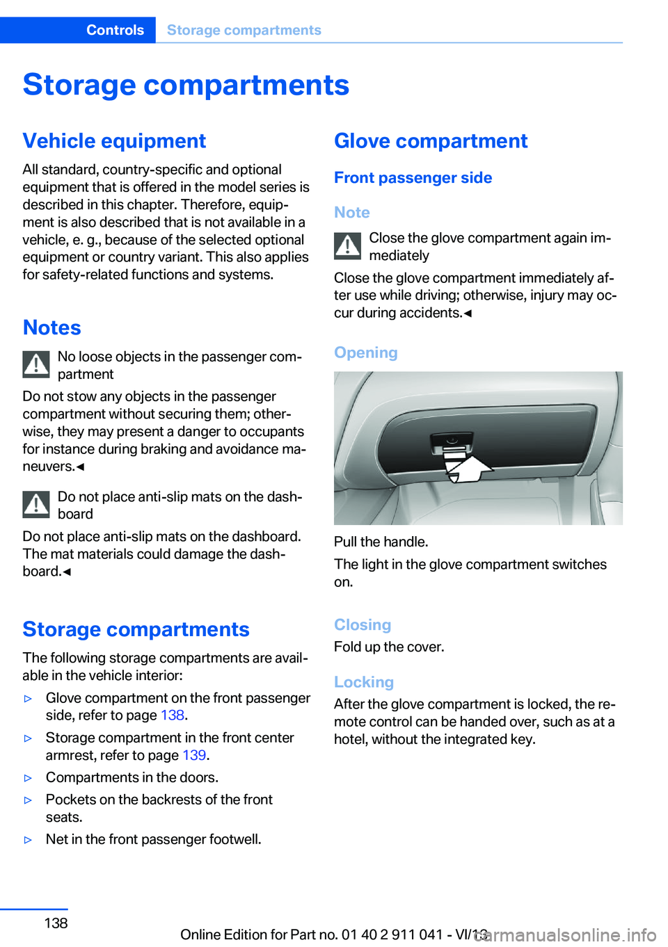
Opening
Pull the handle.
The light in the glove compartment switches
on.
ClosingFold up the cover.
Locking
After the glove compartment is locked, the re‐
mote control can be handed over, such as at a
hotel, without the integrated key.
Seite 138ControlsStorage compartments138
Online Edition for Part no. 01 40 2 911 041 - VI/13
Page 140 of 208
Pushing back the covers
Push back the covers before folding up
the center armrest; otherwise, the cupholder
could become damaged.◀
Clothes hooks
The clothes hooks are located in the grab han‐
dles in the rear.
Do not obstruct view
When suspending clothing from the
hooks, ensure that it will not obstruct the driv‐
er's vision.◀
No heavy objects
Do not hang heavy objects from the
hooks; otherwise, they may present a danger
to passengers during braking and evasive ma‐
neuvers.◀
Storage compartments in the cargo area
Storage space under the cargo floor
cover
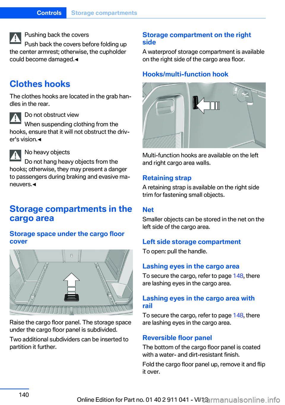
Raise the cargo floor panel. The storage space
under the cargo floor panel is subdivided.
Two additional subdividers can be inserted to
partition it further.
Storage compartment on the right
side
A waterproof storage compartment is available
on the right side of the cargo area floor.
Hooks/multi-function hook
Multi-function hooks are available on the left
and right cargo area walls.
Retaining strapA retaining strap is available on the right side
trim for fastening small objects.
Net
Smaller objects can be stored in the net on the
left side of the cargo area.
Left side storage compartment
To open: pull the handle.
Lashing eyes in the cargo area
To secure the cargo, refer to page 148, there
are lashing eyes in the cargo area.
Lashing eyes in the cargo area with
rail
To secure the cargo, refer to page 148, there
are lashing eyes in the cargo area.
Reversible floor panel
The bottom of the cargo floor panel is coated
with a water- and dirt-resistant finish.
Fold the cargo floor panel up, remove it and flip
it over.
Seite 140ControlsStorage compartments140
Online Edition for Part no. 01 40 2 911 041 - VI/13