2014 BMW X1 XDRIVE 28I lock
[x] Cancel search: lockPage 225 of 295
▷Corresponding mobile wireless contract.
Any additionally incurred costs are not a
part of Apps.▷Use only BMW approved software applica‐
tions; otherwise, it may result in malfunc‐
tions.
Information about suitable mobile phones,
available software applications and their instal‐
lation can be found at www.bmw.com/connec‐
tivity or at the service center.
Create the entries.
Make entries only when traffic and road
conditions allow. Otherwise, the vehicle occu‐
pants and other road users may be put in dan‐
ger because of the distraction from driving.
For reasons of safety, some software applica‐
tions are usable only while the vehicle is sta‐
tionary.◀
Operating Apps
1.Connect the mobile phone via the snap-in
adapter or via the USB audio interface.2."ConnectedDrive"3.Select the desired software application.
Displaying status
Information about the currently available soft‐
ware applications can be displayed.
1."ConnectedDrive"2."BMW apps"
Notes
▷The ranges of Apps that can be displayed
on the Control Display depend on the
range of installed software applications on
the mobile phone.▷The data transmission of the software ap‐
plications from the mobile phone to the ve‐
hicle can last some time. Some software
applications depend on the speed of the
available Internet connection of the mobile
phone.▷Some mobile phones cannot simultane‐
ously use Apps and the Bluetooth hands-
free system.
If necessary, restart the software applica‐
tion on the mobile phone after a phone
conversation.
Remote Services
With Remote Services, a connection can be
established between a mobile phone and the
vehicle. This connection can be used, for ex‐
ample, to lock and unlock the vehicle.
Depending on the vehicle, additional functions
may be available.
To be able to use the functions, the My BMW
Remote app must be downloaded. Operation
takes place via the app.
Alternatively, the functions can also be used
via the ConnectedDrive Hotline.
The operating instructions for the My BMW
Remote app can be found on the Connected‐
Drive portal or at www.bmw.com.
Seite 225ConnectedDriveCommunication225
Online Edition for Part no. 01 40 2 911 269 - VI/13
Page 228 of 295
RefuelingVehicle equipment
This chapter describes all series equipment as
well as country-specific and special equipment
offered for this model series.Therefore, it also
describes equipment that may not be found in
your vehicle, for instance due to the selected
special equipment or the country version. This
also applies to safety-related functions and
systems.
General information Refuel promptly
At the latest, refuel at a range below
30 miles/50 km; otherwise, the engine function
is not ensured and damage may occur.◀
Notes Switch off the engine before refueling
Always switch off the engine before refu‐
eling; otherwise, fuel cannot be added to the tank and a message will be displayed.◀
Observe when handling fuel▷Take all precautionary measures and
observe all applicable regulations
when handling fuel.▷Do not carry any spare fuel containers in
your vehicle. They can develop a leak and
cause an explosion or cause a fire in the
event of an accident.◀Fuel cap
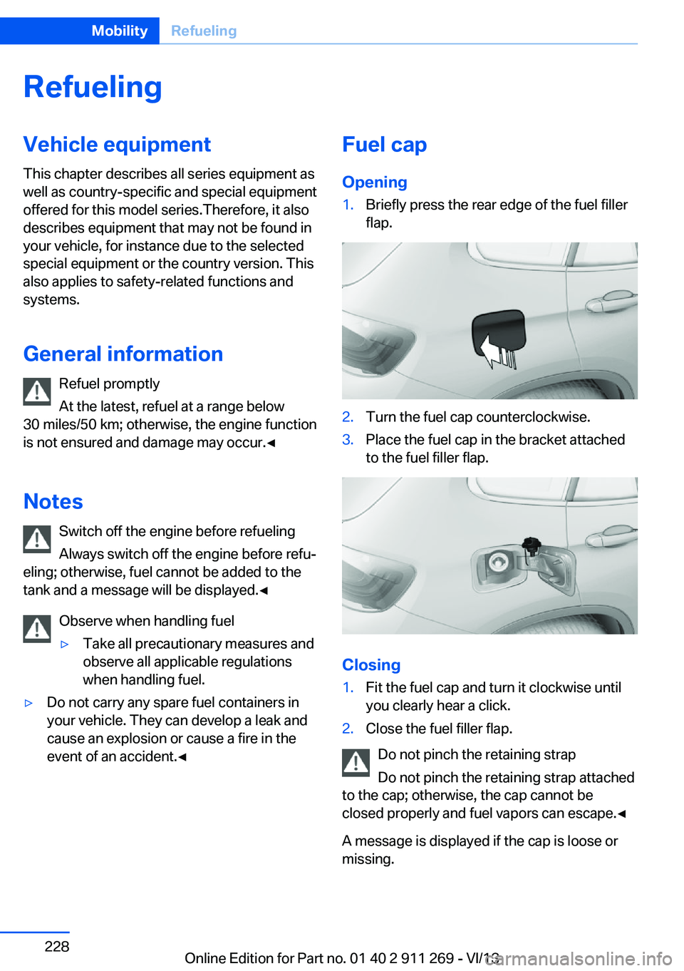
Opening1.Briefly press the rear edge of the fuel filler
flap.2.Turn the fuel cap counterclockwise.3.Place the fuel cap in the bracket attached
to the fuel filler flap.
Closing
1.Fit the fuel cap and turn it clockwise until
you clearly hear a click.2.Close the fuel filler flap.
Do not pinch the retaining strap
Do not pinch the retaining strap attached
to the cap; otherwise, the cap cannot be
closed properly and fuel vapors can escape.◀
A message is displayed if the cap is loose or missing.
Seite 228MobilityRefueling228
Online Edition for Part no. 01 40 2 911 269 - VI/13
Page 229 of 295
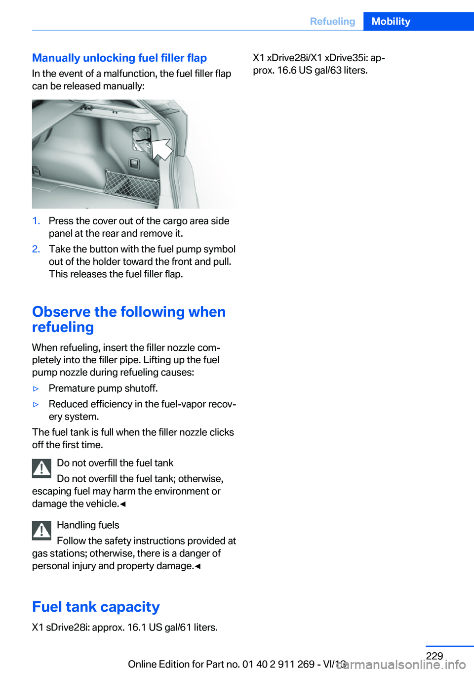
Manually unlocking fuel filler flapIn the event of a malfunction, the fuel filler flap
can be released manually:1.Press the cover out of the cargo area side
panel at the rear and remove it.2.Take the button with the fuel pump symbol
out of the holder toward the front and pull.
This releases the fuel filler flap.
Observe the following when
refueling
When refueling, insert the filler nozzle com‐
pletely into the filler pipe. Lifting up the fuel
pump nozzle during refueling causes:
▷Premature pump shutoff.▷Reduced efficiency in the fuel-vapor recov‐
ery system.
The fuel tank is full when the filler nozzle clicks
off the first time.
Do not overfill the fuel tank
Do not overfill the fuel tank; otherwise,
escaping fuel may harm the environment or
damage the vehicle.◀
Handling fuels
Follow the safety instructions provided at
gas stations; otherwise, there is a danger of
personal injury and property damage.◀
Fuel tank capacity
X1 sDrive28i: approx. 16.1 US gal/61 liters.
X1 xDrive28i/X1 xDrive35i: ap‐
prox. 16.6 US gal/63 liters.Seite 229RefuelingMobility229
Online Edition for Part no. 01 40 2 911 269 - VI/13
Page 246 of 295
Oil changeAn oil change should be carried out by the
service center only.
Coolant
General information Danger of burns from hot engine
Do not open the cooling system while
the engine is hot; otherwise, escaping coolant
may cause burns.◀
Suitable additives
Only use suitable additives; otherwise,
engine damage may occur. The additives are
harmful to your health.◀
Coolant consists of water and additives.
Not all commercially available additives are
suitable for your vehicle. Ask your service cen‐
ter for suitable additives.
Checking the coolant level
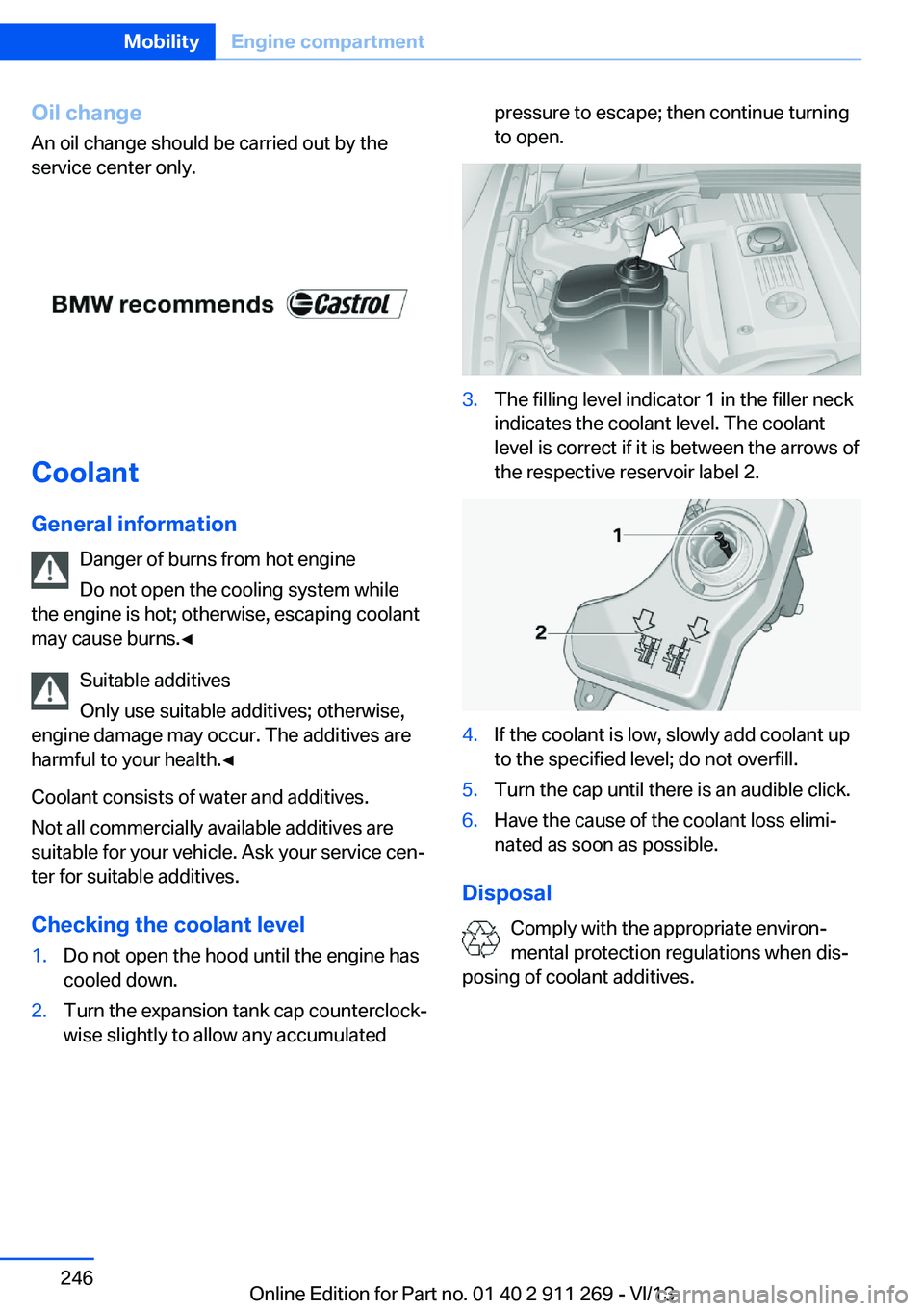
1.Do not open the hood until the engine has
cooled down.2.Turn the expansion tank cap counterclock‐
wise slightly to allow any accumulatedpressure to escape; then continue turning
to open.3.The filling level indicator 1 in the filler neck
indicates the coolant level. The coolant
level is correct if it is between the arrows of
the respective reservoir label 2.4.If the coolant is low, slowly add coolant up
to the specified level; do not overfill.5.Turn the cap until there is an audible click.6.Have the cause of the coolant loss elimi‐
nated as soon as possible.
Disposal
Comply with the appropriate environ‐
mental protection regulations when dis‐
posing of coolant additives.
Seite 246MobilityEngine compartment246
Online Edition for Part no. 01 40 2 911 269 - VI/13
Page 249 of 295
Replacing componentsVehicle equipmentThis chapter describes all series equipment as
well as country-specific and special equipment
offered for this model series.Therefore, it also
describes equipment that may not be found in
your vehicle, for instance due to the selected
special equipment or the country version. This
also applies to safety-related functions and
systems.
Tool kit
The tool kit is stowed under the cargo floor
panel and storage compartment in the cargo
area.
Wiper blade replacement Do not fold down the wipers without
wiper blades
Do not fold down the wipers if wiper blades
have not been installed; this may damage the
windshield.◀
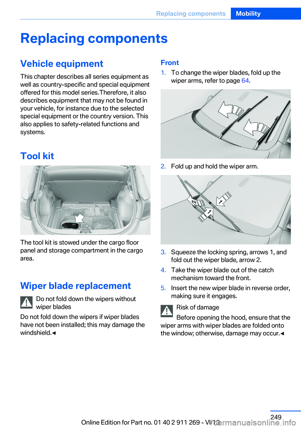
Front1.To change the wiper blades, fold up the
wiper arms, refer to page 64.2.Fold up and hold the wiper arm.3.Squeeze the locking spring, arrows 1, and
fold out the wiper blade, arrow 2.4.Take the wiper blade out of the catch
mechanism toward the front.5.Insert the new wiper blade in reverse order,
making sure it engages.
Risk of damage
Before opening the hood, ensure that the
wiper arms with wiper blades are folded onto
the window; otherwise, damage may occur.◀
Seite 249Replacing componentsMobility249
Online Edition for Part no. 01 40 2 911 269 - VI/13
Page 250 of 295
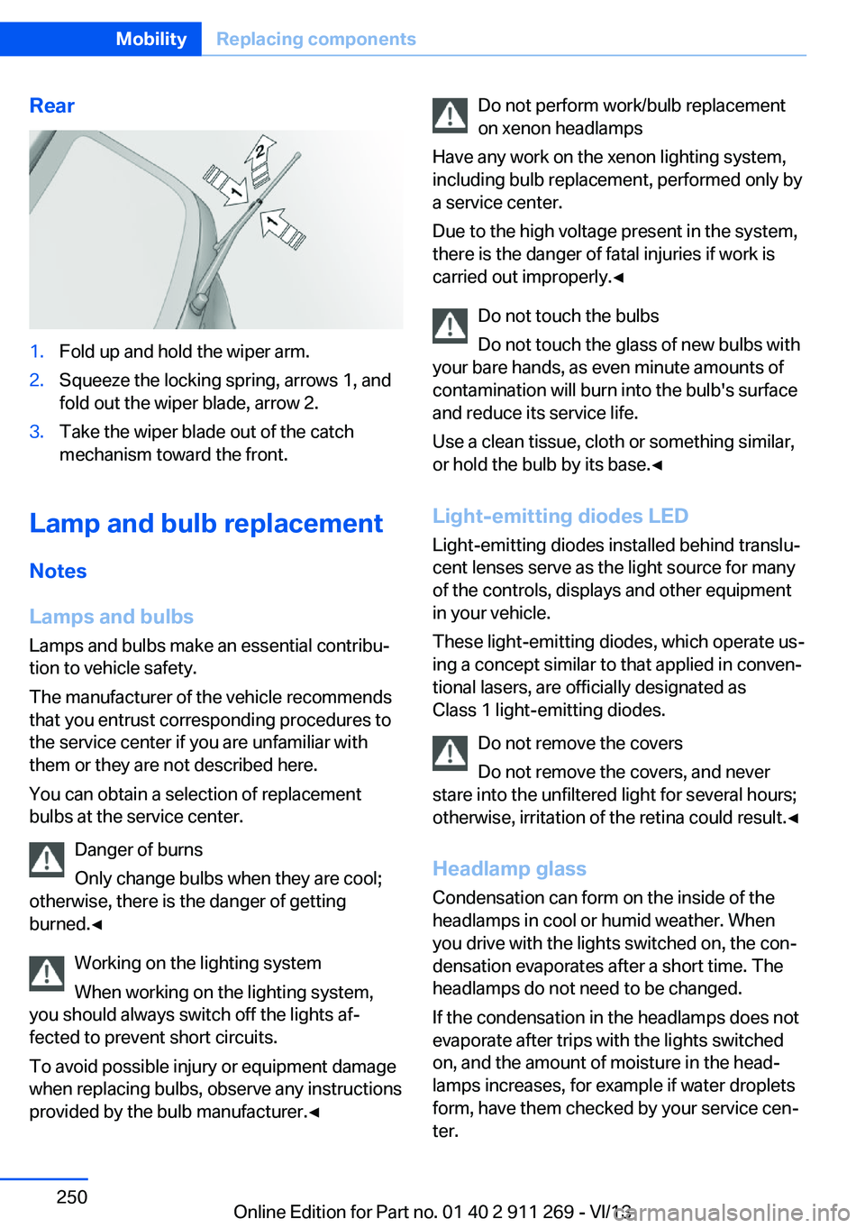
Rear1.Fold up and hold the wiper arm.2.Squeeze the locking spring, arrows 1, and
fold out the wiper blade, arrow 2.3.Take the wiper blade out of the catch
mechanism toward the front.
Lamp and bulb replacement
Notes
Lamps and bulbs
Lamps and bulbs make an essential contribu‐
tion to vehicle safety.
The manufacturer of the vehicle recommends
that you entrust corresponding procedures to
the service center if you are unfamiliar with them or they are not described here.
You can obtain a selection of replacement
bulbs at the service center.
Danger of burns
Only change bulbs when they are cool;
otherwise, there is the danger of getting
burned.◀
Working on the lighting system
When working on the lighting system,
you should always switch off the lights af‐
fected to prevent short circuits.
To avoid possible injury or equipment damage
when replacing bulbs, observe any instructions
provided by the bulb manufacturer.◀
Do not perform work/bulb replacement
on xenon headlamps
Have any work on the xenon lighting system,
including bulb replacement, performed only by
a service center.
Due to the high voltage present in the system,
there is the danger of fatal injuries if work is
carried out improperly.◀
Do not touch the bulbs
Do not touch the glass of new bulbs with
your bare hands, as even minute amounts of
contamination will burn into the bulb's surface
and reduce its service life.
Use a clean tissue, cloth or something similar,
or hold the bulb by its base.◀
Light-emitting diodes LED
Light-emitting diodes installed behind translu‐
cent lenses serve as the light source for many
of the controls, displays and other equipment
in your vehicle.
These light-emitting diodes, which operate us‐
ing a concept similar to that applied in conven‐
tional lasers, are officially designated as
Class 1 light-emitting diodes.
Do not remove the covers
Do not remove the covers, and never
stare into the unfiltered light for several hours; otherwise, irritation of the retina could result.◀
Headlamp glass
Condensation can form on the inside of the
headlamps in cool or humid weather. When
you drive with the lights switched on, the con‐
densation evaporates after a short time. The
headlamps do not need to be changed.
If the condensation in the headlamps does not
evaporate after trips with the lights switched
on, and the amount of moisture in the head‐
lamps increases, for example if water droplets
form, have them checked by your service cen‐
ter.Seite 250MobilityReplacing components250
Online Edition for Part no. 01 40 2 911 269 - VI/13
Page 251 of 295
Removing the headlamp cover
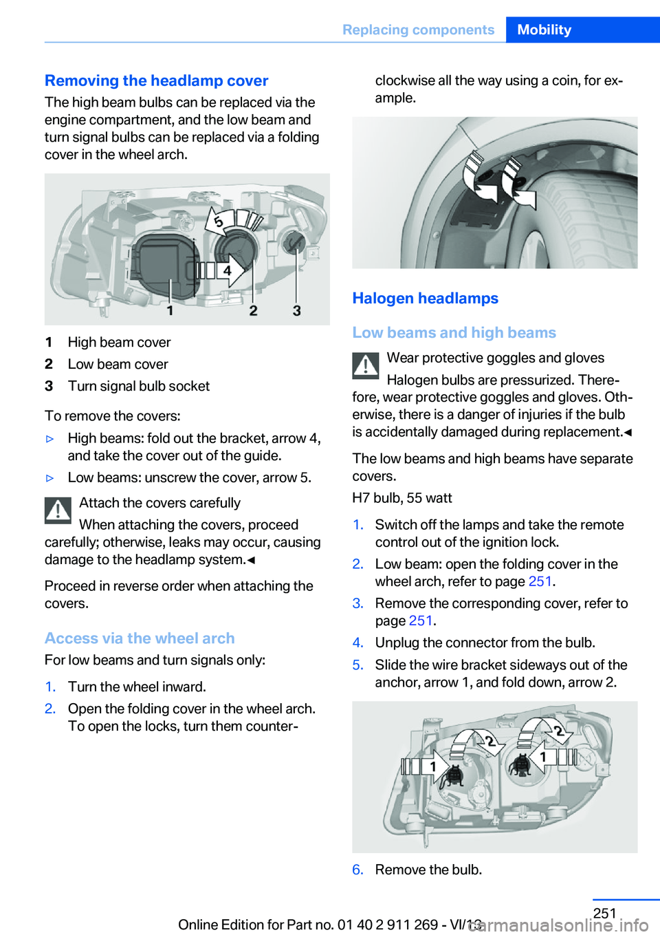
The high beam bulbs can be replaced via the
engine compartment, and the low beam and
turn signal bulbs can be replaced via a folding
cover in the wheel arch.1High beam cover2Low beam cover3Turn signal bulb socket
To remove the covers:
▷High beams: fold out the bracket, arrow 4,
and take the cover out of the guide.▷Low beams: unscrew the cover, arrow 5.
Attach the covers carefully
When attaching the covers, proceed
carefully; otherwise, leaks may occur, causing
damage to the headlamp system.◀
Proceed in reverse order when attaching the
covers.
Access via the wheel arch For low beams and turn signals only:
1.Turn the wheel inward.2.Open the folding cover in the wheel arch.
To open the locks, turn them counter‐clockwise all the way using a coin, for ex‐
ample.
Halogen headlamps
Low beams and high beams Wear protective goggles and gloves
Halogen bulbs are pressurized. There‐
fore, wear protective goggles and gloves. Oth‐
erwise, there is a danger of injuries if the bulb
is accidentally damaged during replacement.◀
The low beams and high beams have separate
covers.
H7 bulb, 55 watt
1.Switch off the lamps and take the remote
control out of the ignition lock.2.Low beam: open the folding cover in the
wheel arch, refer to page 251.3.Remove the corresponding cover, refer to
page 251.4.Unplug the connector from the bulb.5.Slide the wire bracket sideways out of the
anchor, arrow 1, and fold down, arrow 2.6.Remove the bulb.Seite 251Replacing componentsMobility251
Online Edition for Part no. 01 40 2 911 269 - VI/13
Page 252 of 295
7.Insert the new bulb.8.Fold up the wire bracket and lock it.9.Plug in the connector.10.Reattach the cover.11.Low beam: attach the folding cover in the
wheel arch.
Parking and roadside parking lamps
5-watt bulb, W5W
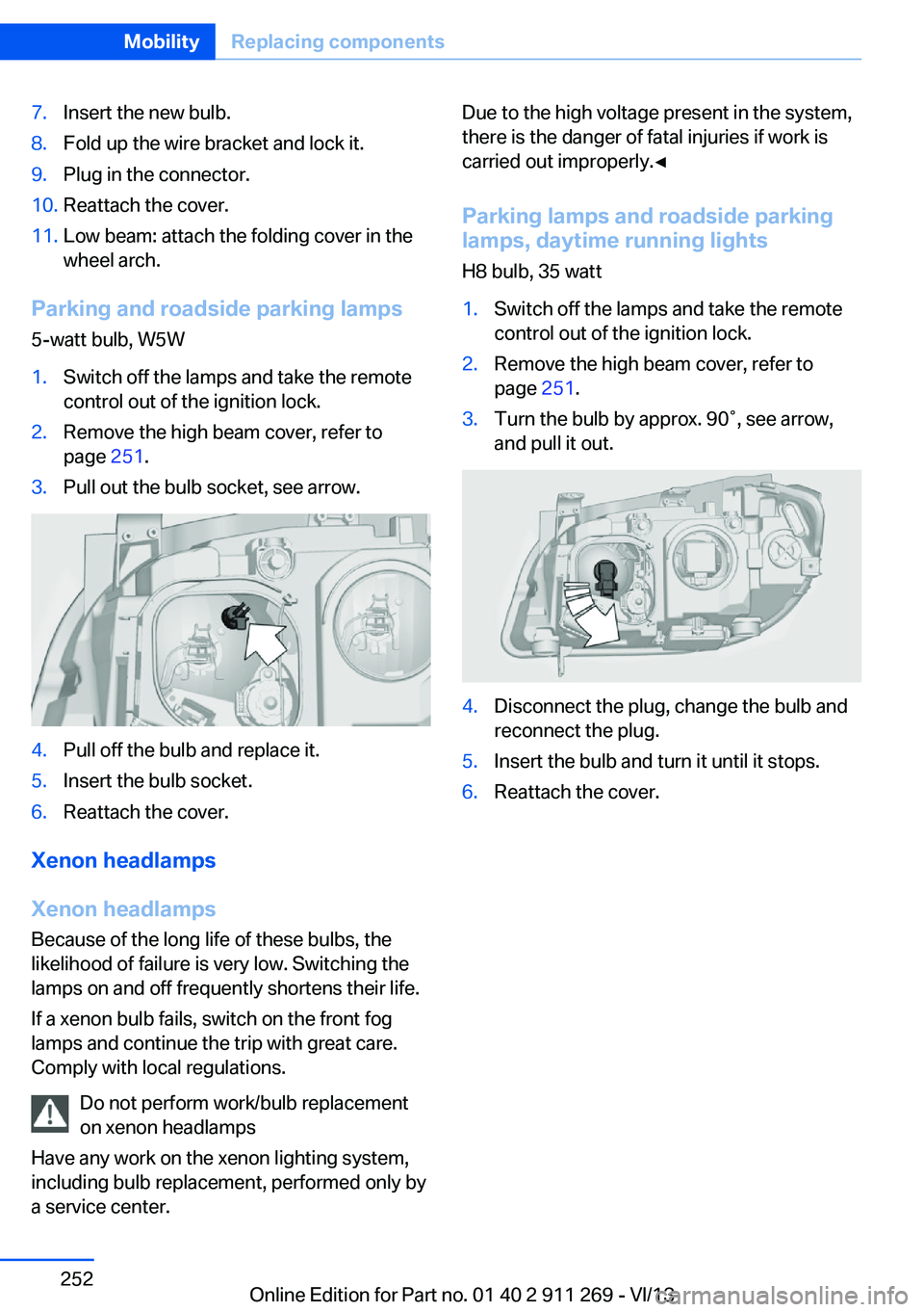
1.Switch off the lamps and take the remote
control out of the ignition lock.2.Remove the high beam cover, refer to
page 251.3.Pull out the bulb socket, see arrow.4.Pull off the bulb and replace it.5.Insert the bulb socket.6.Reattach the cover.
Xenon headlamps
Xenon headlamps Because of the long life of these bulbs, the
likelihood of failure is very low. Switching the
lamps on and off frequently shortens their life.
If a xenon bulb fails, switch on the front fog
lamps and continue the trip with great care.
Comply with local regulations.
Do not perform work/bulb replacement
on xenon headlamps
Have any work on the xenon lighting system,
including bulb replacement, performed only by
a service center.
Due to the high voltage present in the system,
there is the danger of fatal injuries if work is
carried out improperly.◀
Parking lamps and roadside parkinglamps, daytime running lights
H8 bulb, 35 watt1.Switch off the lamps and take the remote
control out of the ignition lock.2.Remove the high beam cover, refer to
page 251.3.Turn the bulb by approx. 90˚, see arrow,
and pull it out.4.Disconnect the plug, change the bulb and
reconnect the plug.5.Insert the bulb and turn it until it stops.6.Reattach the cover.Seite 252MobilityReplacing components252
Online Edition for Part no. 01 40 2 911 269 - VI/13