2014 BMW X1 XDRIVE 28I ECU
[x] Cancel search: ECUPage 135 of 295
Load
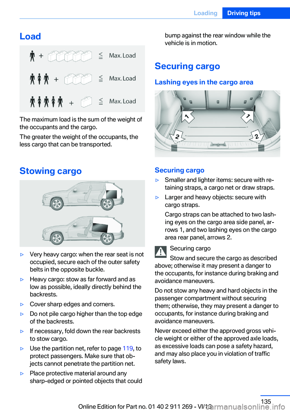
The maximum load is the sum of the weight of
the occupants and the cargo.
The greater the weight of the occupants, the
less cargo that can be transported.
Stowing cargo
▷Very heavy cargo: when the rear seat is not
occupied, secure each of the outer safety
belts in the opposite buckle.▷Heavy cargo: stow as far forward and as
low as possible, ideally directly behind the
backrests.▷Cover sharp edges and corners.▷Do not pile cargo higher than the top edge
of the backrests.▷If necessary, fold down the rear backrests
to stow cargo.▷Use the partition net, refer to page 119, to
protect passengers. Make sure that ob‐
jects cannot penetrate the partition net.▷Place protective material around any
sharp-edged or pointed objects that couldbump against the rear window while the
vehicle is in motion.
Securing cargo
Lashing eyes in the cargo area
Securing cargo
▷Smaller and lighter items: secure with re‐
taining straps, a cargo net or draw straps.▷Larger and heavy objects: secure with
cargo straps.
Cargo straps can be attached to two lash‐
ing eyes on the cargo area side panel, ar‐
rows 1, and two lashing eyes on the cargo
area rear panel, arrows 2.
Securing cargo
Stow and secure the cargo as described
above; otherwise it may present a danger to
the occupants, for instance during braking and
avoidance maneuvers.
Do not stow any heavy and hard objects in the
passenger compartment without securing
them; otherwise, they may present a danger to
occupants, for instance during braking and
avoidance maneuvers.
Never exceed either the approved gross vehi‐
cle weight or either of the approved axle loads,
as excessive loads can pose a safety hazard,
and may also place you in violation of traffic
safety laws.
Seite 135LoadingDriving tips135
Online Edition for Part no. 01 40 2 911 269 - VI/13
Page 136 of 295
Use only the lashing eyes pictured to fasten
the heavy-duty cargo straps. Do not secure
cargo using the upper top tether, refer to
page 53, mounting points; otherwise, these
may become damaged.◀
Roof-mounted luggage rack
Notes A special rack system is available as an op‐
tional accessory.
Anchorage points The anchorage points are located on the roof
railing.
Attachment Follow the installation instructions for the roof-
mounted luggage rack.
Be sure that adequate clearance is maintained
for tilting and opening the panoramic glass
sunroof.
Loading Because roof racks raise the vehicle's center
of gravity when loaded, they have a major ef‐
fect on vehicle handling and steering re‐
sponse.
Therefore, note the following when loading
and driving:▷Do not exceed the approved roof/axle
loads and the approved gross vehicle
weight.▷Distribute the roof load uniformly.▷The roof load should not be too large in
area.▷Always load the heaviest pieces on the
bottom.▷Fasten the roof-mounted luggage se‐
curely, for instance using lashing straps.▷Do not let objects project into the opening
path of the tailgate.▷Drive smoothly. Avoid sudden acceleration
and braking maneuvers. Take corners gen‐
tly.
Rear luggage rack
Notes A special rear rack is available as an optional
accessory. It does not require a trailer hitch.
Follow the installation instructions for the rear
rack.
Anchorage points
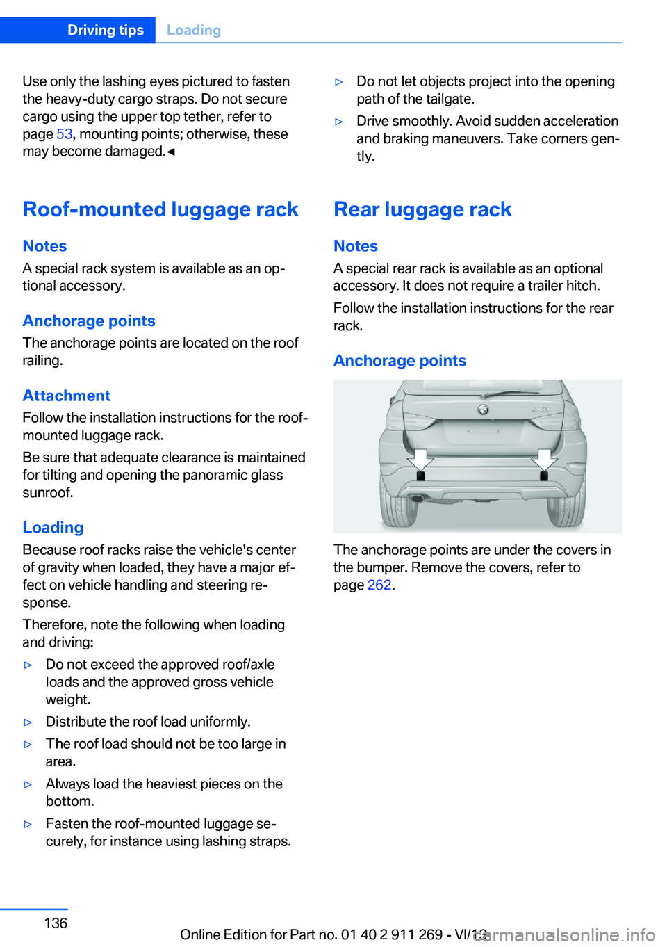
The anchorage points are under the covers in
the bumper. Remove the covers, refer to
page 262.
Seite 136Driving tipsLoading136
Online Edition for Part no. 01 40 2 911 269 - VI/13
Page 197 of 295
Notes
At high temperatures, the charging function of the mobile phone may be limited and functions
may not be executed.
When using the mobile phone via the vehicle,
note the operating instructions of the mobile
phone.
Pairing/unpairing the mobile
phone
General information
The following functions are available:▷Use of a mobile phone as a telephone.▷Use of a mobile phone as an additional te‐
lephone.▷Use of a mobile phone as an audio source.▷Use of an audio device as an audio source,
refer to page 187.
Requirements
▷The mobile phone is suitable, refer to
page 196.▷The mobile phone is ready for operation.▷Bluetooth is activated in the vehicle and on
the mobile phone.▷Bluetooth presettings may need to be
made on the mobile phone, e.g., for a con‐
nection without confirmation or visibility,
refer to the mobile phone operating in‐
structions.▷Deactivate Bluetooth audio if necessary.▷A number with at least four and a maximum
of 16 digits was defined as the Bluetooth
passkey. It is only required once for pairing.▷The ignition is switched on.Activating/deactivating Bluetooth
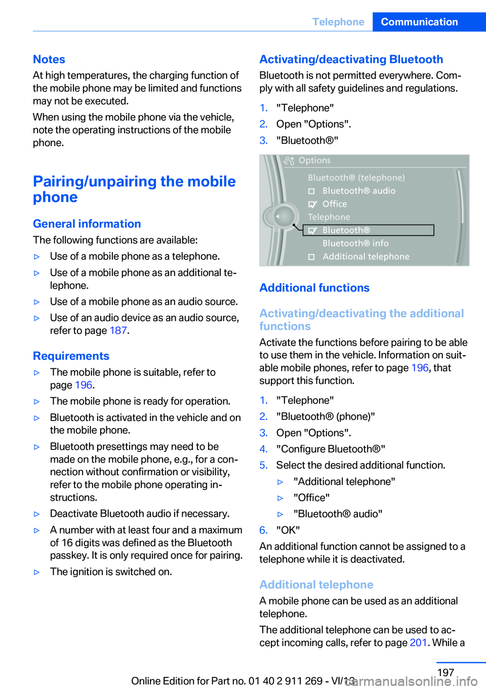
Bluetooth is not permitted everywhere. Com‐
ply with all safety guidelines and regulations.1."Telephone"2.Open "Options".3."Bluetooth®"
Additional functions
Activating/deactivating the additional
functions
Activate the functions before pairing to be able
to use them in the vehicle. Information on suit‐
able mobile phones, refer to page 196, that
support this function.
1."Telephone"2."Bluetooth® (phone)"3.Open "Options".4."Configure Bluetooth®"5.Select the desired additional function.▷"Additional telephone"▷"Office"▷"Bluetooth® audio"6."OK"
An additional function cannot be assigned to a
telephone while it is deactivated.
Additional telephone A mobile phone can be used as an additional
telephone.
The additional telephone can be used to ac‐
cept incoming calls, refer to page 201. While a
Seite 197TelephoneCommunication197
Online Edition for Part no. 01 40 2 911 269 - VI/13
Page 198 of 295
call is active on the additional telephone, re‐
ceived calls are displayed on the Control Dis‐
play.
Audio source
A mobile phone can be used as an audio
source.
Pairing and connecting a mobile
phone
Pairing the mobile phone
To avoid becoming distracted and pos‐
ing an unnecessary hazard both to your own
vehicle's occupants and to other road users,
only pair the mobile phone while the vehicle is
stationary.◀1."Telephone"2."Bluetooth® (phone)"3."Add new phone"
The Bluetooth name of the vehicle is dis‐
played.4.To perform additional steps on the mobile
phone, refer to the mobile phone operating
instructions: for instance, search for or
connect the Bluetooth device or a new de‐
vice.
The Bluetooth name of the vehicle appears
on the mobile phone display.5.Select the Bluetooth name of the vehicle
on the mobile phone display.6.You are prompted by the iDrive or mobile
phone to enter the same Bluetooth pass‐
key. Enter the passkey and confirm.
or
Compare the control number on the vehi‐
cle display with the control number on the
mobile phone display. Confirm the control
number on the mobile phone and in the ve‐
hicle.
"OK"7.Select the functions for which the mobile
phone is to be used.8."OK"
If the pairing was successful, the mobile phone
appears at the top of the list of mobile phones.
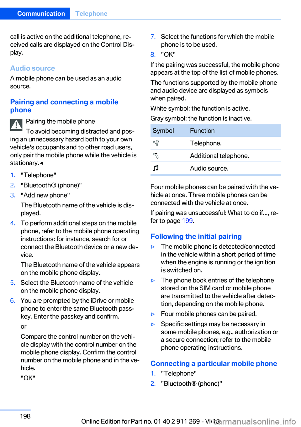
The functions supported by the mobile phone
and audio device are displayed as symbols
when paired.
White symbol: the function is active.
Gray symbol: the function is inactive.
SymbolFunction Telephone. Additional telephone. Audio source.
Four mobile phones can be paired with the ve‐
hicle at once. Three mobile phones can be
connected with the vehicle at once.
If pairing was unsuccessful: What to do if..., re‐
fer to page 199.
Following the initial pairing
▷The mobile phone is detected/connected
in the vehicle within a short period of time
when the engine is running or the ignition
is switched on.▷The phone book entries of the telephone
stored on the SIM card or mobile phone
are transmitted to the vehicle after detec‐
tion, depending on the mobile phone.▷Four mobile phones can be paired.▷Specific settings may be necessary in
some mobile phones, e.g., authorization or
a secure connection; refer to the mobile
phone operating instructions.
Connecting a particular mobile phone
1."Telephone"2."Bluetooth® (phone)"Seite 198CommunicationTelephone198
Online Edition for Part no. 01 40 2 911 269 - VI/13
Page 207 of 295
Snap-in adapter
General information More information on compatible snap-in
adapters that support the functions of the mo‐
bile phone is available at the service center.
Notes At high temperatures, the charging function of
the mobile phone may be limited and functions
may not be executed.
When using the mobile phone via the vehicle,
note the operating instructions of the mobile
phone.
Installation position
In the center armrest.
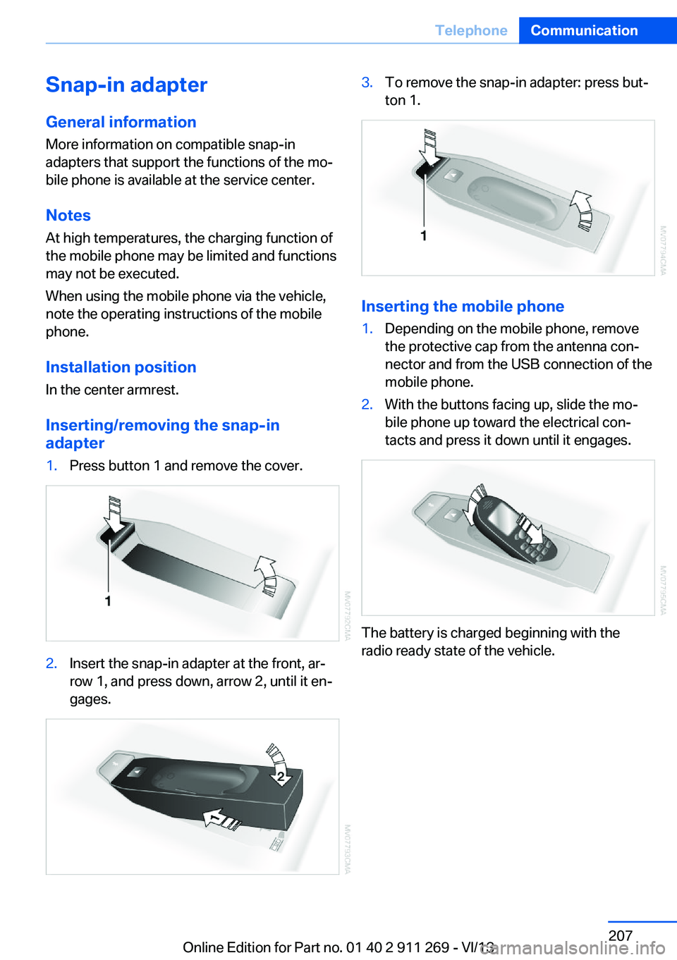
Inserting/removing the snap-in
adapter1.Press button 1 and remove the cover.2.Insert the snap-in adapter at the front, ar‐
row 1, and press down, arrow 2, until it en‐
gages.3.To remove the snap-in adapter: press but‐
ton 1.
Inserting the mobile phone
1.Depending on the mobile phone, remove
the protective cap from the antenna con‐
nector and from the USB connection of the
mobile phone.2.With the buttons facing up, slide the mo‐
bile phone up toward the electrical con‐
tacts and press it down until it engages.
The battery is charged beginning with the
radio ready state of the vehicle.
Seite 207TelephoneCommunication207
Online Edition for Part no. 01 40 2 911 269 - VI/13
Page 243 of 295
Risk of damage
Before opening the hood, ensure that the
wiper arms with wiper blades are folded onto
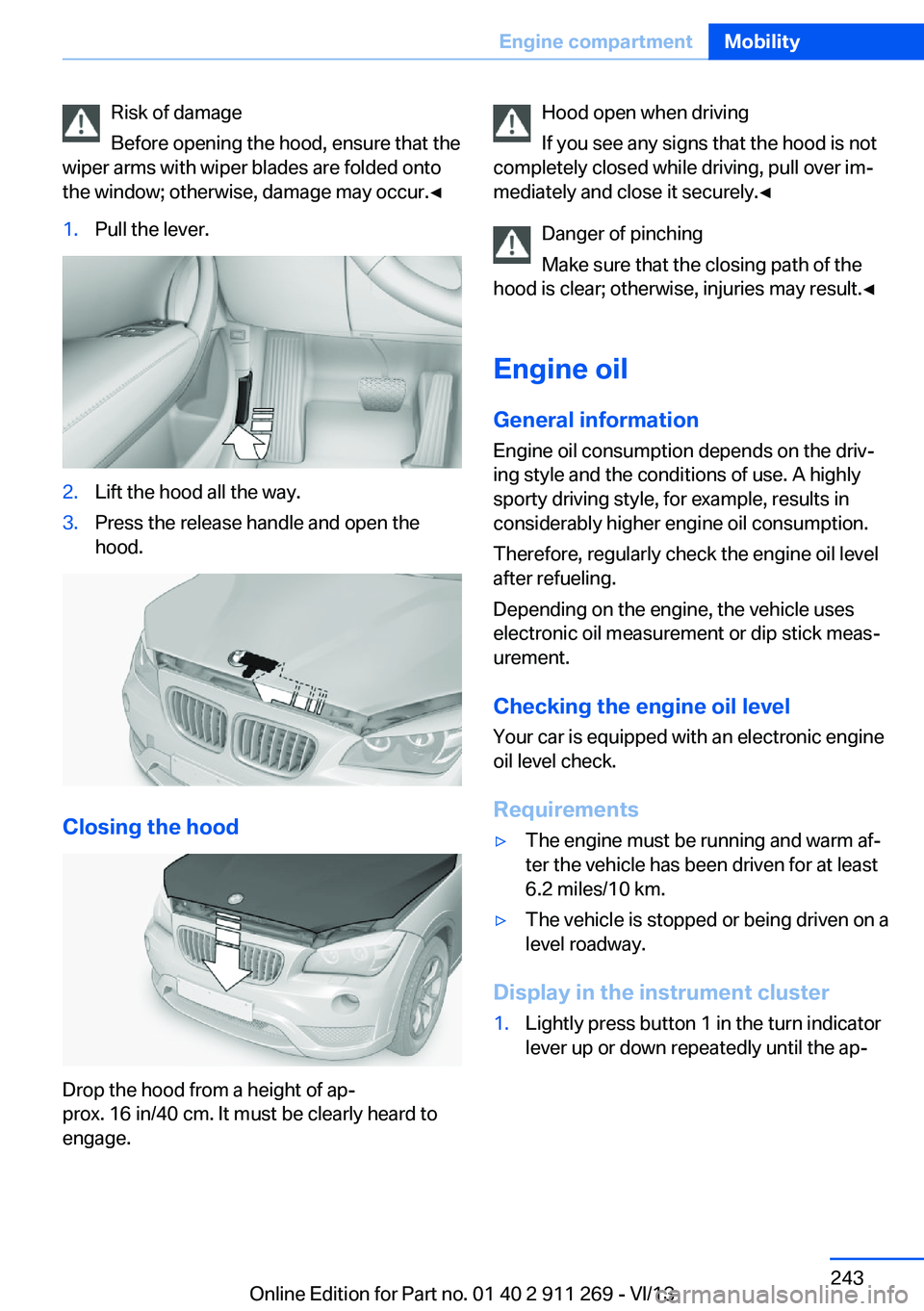
the window; otherwise, damage may occur.◀1.Pull the lever.2.Lift the hood all the way.3.Press the release handle and open the
hood.
Closing the hood
Drop the hood from a height of ap‐
prox. 16 in/40 cm. It must be clearly heard to
engage.
Hood open when driving
If you see any signs that the hood is not
completely closed while driving, pull over im‐
mediately and close it securely.◀
Danger of pinching
Make sure that the closing path of the
hood is clear; otherwise, injuries may result.◀
Engine oil
General information Engine oil consumption depends on the driv‐
ing style and the conditions of use. A highly
sporty driving style, for example, results in
considerably higher engine oil consumption.
Therefore, regularly check the engine oil level
after refueling.
Depending on the engine, the vehicle uses
electronic oil measurement or dip stick meas‐
urement.
Checking the engine oil level Your car is equipped with an electronic engine
oil level check.
Requirements▷The engine must be running and warm af‐
ter the vehicle has been driven for at least
6.2 miles/10 km.▷The vehicle is stopped or being driven on a
level roadway.
Display in the instrument cluster
1.Lightly press button 1 in the turn indicator
lever up or down repeatedly until the ap‐Seite 243Engine compartmentMobility243
Online Edition for Part no. 01 40 2 911 269 - VI/13
Page 256 of 295
Maintain the battery in an upright position for
transport and storage. Secure the battery so
that it does not tip over during transport.
Fuses Replacing fuses
Never attempt to repair a blown fuse and
do not replace a defective fuse with a substi‐
tute of another color or amperage rating; this
could lead to a circuit overload, ultimately re‐
sulting in a fire in the vehicle.◀
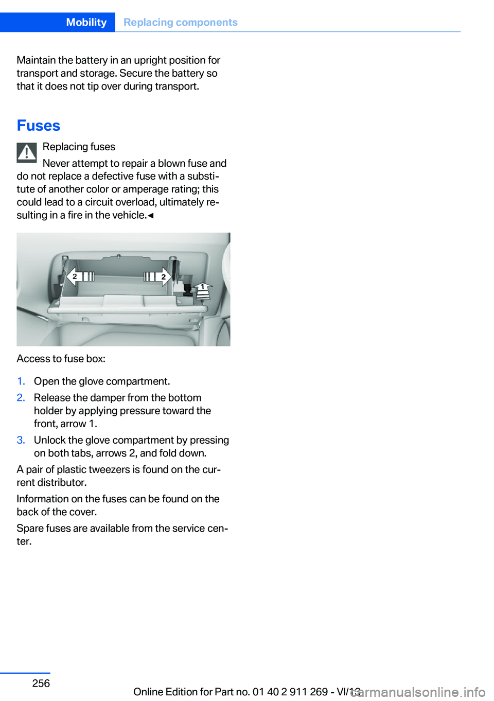
Access to fuse box:
1.Open the glove compartment.2.Release the damper from the bottom
holder by applying pressure toward the
front, arrow 1.3.Unlock the glove compartment by pressing
on both tabs, arrows 2, and fold down.
A pair of plastic tweezers is found on the cur‐
rent distributor.
Information on the fuses can be found on the
back of the cover.
Spare fuses are available from the service cen‐
ter.
Seite 256MobilityReplacing components256
Online Edition for Part no. 01 40 2 911 269 - VI/13
Page 262 of 295
Attaching the tow rope correctly
Only secure the tow rope on the tow fit‐
ting; otherwise, damage can occur when it is
secured on other parts of the vehicle.◀
Tow fitting
The screw-in tow fitting should always be car‐
ried in the vehicle. It can be screwed in at the
front or rear of the BMW.
It is located in the tool kit under the cargo floor
cover and storage compartment in the cargo
area, refer to page 249.
It is stored with the tool kit under the cargo
floor cover in the cargo area, refer to page 249.
Tow fitting, information on use▷Use only the tow fitting provided with
the vehicle and screw it all the way in.▷Use the tow fitting for towing on paved
roads only.▷Avoid lateral loading of the tow fitting, e.g.,
do not lift the vehicle by the tow fitting.
Otherwise, damage to the tow fitting and the
vehicle can occur.◀
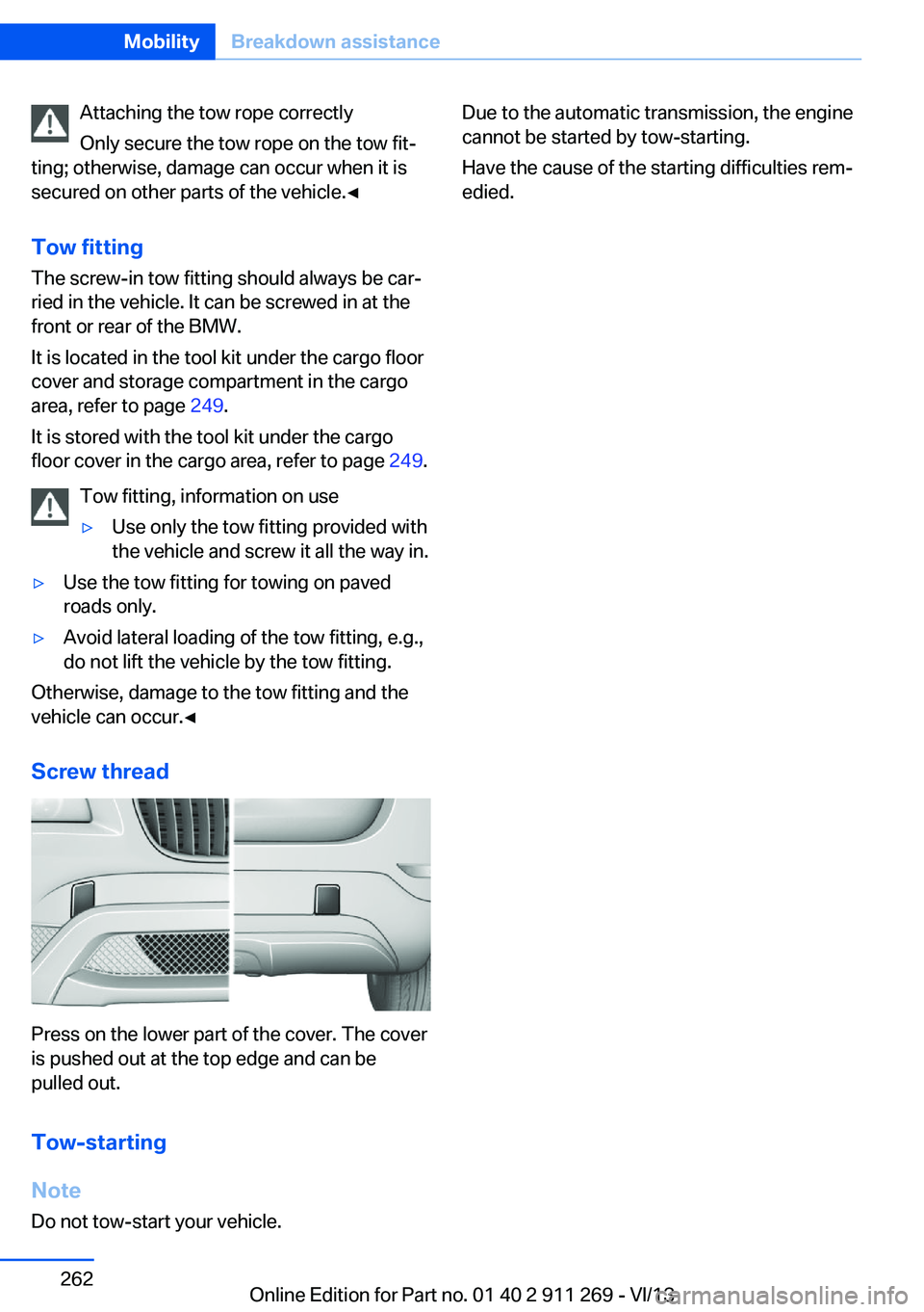
Screw thread
Press on the lower part of the cover. The cover
is pushed out at the top edge and can be
pulled out.
Tow-starting
Note Do not tow-start your vehicle.
Due to the automatic transmission, the engine
cannot be started by tow-starting.
Have the cause of the starting difficulties rem‐
edied.Seite 262MobilityBreakdown assistance262
Online Edition for Part no. 01 40 2 911 269 - VI/13