2014 BMW M235I Amp
[x] Cancel search: AmpPage 112 of 218
Indicator/warning lamps
When DSC is deactivated, DSC OFF is dis‐
played in the instrument cluster.
The indicator lamp lights up: DSC is
deactivated.
DTC Dynamic Traction
Control
The concept The DTC system is a version of the DSC in
which forward momentum is optimized.
The system ensures maximum forward mo‐
mentum on special road conditions, e.g., unp‐
lowed snowy roads, but driving stability is lim‐
ited.
It is therefore necessary to drive with appropri‐
ate caution.
You may find it useful to briefly activate DTC
under the following special circumstances:▷When driving in slush or on uncleared,
snow-covered roads.▷When rocking the vehicle or driving off in
deep snow or on loose surfaces.▷When driving with snow chains.
Deactivating/activating DTC Dynamic
Traction Control
Activating the Dynamic Traction Control DTC
provides maximum traction on loose ground.
Driving stability is limited during acceleration
and when driving in bends.
Activating DTC Press the button.
TRACTION is displayed in the instru‐
ment cluster and the indicator lamp for DSC
OFF lights up.
Deactivating DTC
Press the button again.
TRACTION and the DSC OFF indica‐
tor lamp go out.
Above 31 mph/50 km/h DTC is automatically
deactivated.
Variable sport steering The variable sport steering increases the
steering angle of the front wheels at large
steering wheel angles, e.g., in tight curves or
when parking. Steering becomes more direct.
It also varies the force required to turn the
wheels in accordance with the vehicle speed.
This results in a sporty steering response. In
addition, it becomes easier to steer during
parking and maneuvering.
Driving Dynamics Control
The concept The Driving Dynamics Control can be used to
adjust the certain characteristics of the vehicle.
Various programs can be selected for this pur‐
pose. The Driving Dynamics Control and the
DSC OFF buttons can each be used to activate
a program.
Operating the programsPress the buttonProgramDSC OFF
TRACTIONSPORT+
SPORT
COMFORT
ECO PROSeite 112ControlsDriving stability control systems112
Online Edition for Part no. 01 40 2 924 974 - X/13
Page 113 of 218
Automatic program change
The system automatically switches to COM‐
FORT in the following situations:▷Failure of DSC Dynamic Damping Control.▷The vehicle has a flat tire.▷When activating cruise control in TRAC‐
TION or DSC OFF mode.
DSC OFF
When DSC OFF, refer to page 111, is active,
driving stability is limited during acceleration
and when driving in bends.
TRACTION When TRACTION is active, the vehicle has
maximum traction on loose road surfaces. DTC
Dynamic Traction Control, refer to page 112, is
activated. Driving stability is limited during ac‐
celeration and when driving in bends.
SPORT+
Sporty driving with optimized chassis and
adapted engine control with limited driving sta‐
bilization.
Dynamic Traction Control is switched on.
The driver handles several of the stabilization
tasks.
Activating SPORT+ Press the button repeatedly until
SPORT+ appears in the instrument
cluster and the DSC OFF indicator lamp lights
up.
Automatic program change When activating cruise control, the program
automatically switches to SPORT mode.
Indicator/warning lamps
SPORT+ is displayed in the instrument cluster.
The DSC OFF indicator lamp lights up:
Dynamic Traction Control is activated.
SPORT Consistently sporty tuning of the suspension
and engine control for greater driving agility
with maximum driving stabilization.
The program can be configured to individual
specifications. The configuration is stored for
the remote control currently in use.
Activating SPORT Press button repeatedly until SPORT
is displayed in the instrument cluster.
Configuring SPORT When the display is activated on the ControlDisplay, refer to page 114, the SPORT driving
mode can be set to individual specifications.▷Activating SPORT.▷"Configure SPORT"▷Configuring the SPORT driving mode.
SPORT can also be configured before it is acti‐
vated:
1."Settings"2."Driving mode"3."Configure SPORT"4.Configure driving mode.
This configuration is retrieved when the
SPORT driving mode is activated.
COMFORT For a balanced tuning with maximum driving
stabilization.
Activating COMFORT Press button repeatedly until COM‐
FORT is displayed in the instrument
cluster.
Seite 113Driving stability control systemsControls113
Online Edition for Part no. 01 40 2 924 974 - X/13
Page 117 of 218

Resuming the desired speedPress the button.
The stored speed is reached and maintained. Displays in the instrument cluster
Indicator lamp Depending on how the vehicle is equip‐
ped, the indicator lamp in the instru‐
ment cluster indicates whether the sys‐
tem is switched on.
Desired speed▷The marking lights up green:
the system is active.▷The marking lights up or‐
ange: the system has been
interrupted.▷The marking does not light up: the system
is switched off.
Brief status display
Selected desired speed.
If --- appears briefly on the display for Check
Control messages, it is possible that the sys‐
tem requirements for operation are currently
not met.
PDC Park Distance Control
The concept PDC supports you when parking. Objects that
you are approaching slowly in front of or be‐
hind your vehicle are indicated with:
▷Signal tones.▷Visual display.General information
Measurements are made by ultrasound sen‐
sors in the bumpers.
The range, depending on the environment, is
approx. 6 ft/2 m.
An acoustic warning is first given:▷By the front middle sensors and the two
corner sensors at approx. 24 in/60 cm.▷By the rear middle sensors at approx.
5 ft/1.50 m.
To ensure full operability:
▷Do not cover sensors, e.g., by stickers, bi‐
cycle racks and the like.▷Keep the sensors clean and free of ice.▷When using high-pressure washers, do not
spray the sensors for long periods and
maintain a distance of at least 12 in/30 cm.
Hints
Personal responsibility
Even an active system does not relieve
the driver from personal responsibility for the
driving process.
Because of technical system limits, the system
cannot independently react appropriately in all
traffic situations.
Continuously and attentively monitor the driv‐
ing process, the area surrounding the vehicle
and the traffic situation, and actively intervene
when required, otherwise, there is a risk of an
accident.◀
Avoid driving quickly with PDC
Avoid approaching an object quickly.
Avoid driving away quickly while PDC is not yet
active.
For technical reasons, the system may other‐
wise be too late in issuing a warning.◀
Seite 117Driving comfortControls117
Online Edition for Part no. 01 40 2 924 974 - X/13
Page 118 of 218

At a glance
Button in the vehicle
PDC Park Distance Control
Switching on/off
Switching on automatically Select transmission position R with the engine
running.
Automatic deactivation during forward
travel
The system switches off when a certain driving
distance or speed is exceeded.
Switch the system back on if necessary.
Switching on/off manually Press the button.
▷On: the LED lights up.▷Off: the LED goes out.
In addition to the PDC Park Distance Control,
the rearview camera, refer to page 119, can be
switched on.
Switching on the rearview camera viathe iDrive
With PDC activated:
"Rear view camera"
The rearview camera image is displayed. The
setting is stored for the remote control cur‐
rently in use.
Display
Signal tones When approaching an object, an intermittent
tone is sounded that indicates the position of
the object. For example, if an object is de‐
tected to the left rear of the vehicle, a signal
tone sounds from the left rear speaker.
The shorter the distance to the object be‐
comes, the shorter the intervals.
If the distance to a detected object is less than
approx. 10 in/25 cm, a continuous tone is
sounded.
If objects are located both in front of and be‐
hind the vehicle, an alternating continuous sig‐
nal is sounded.
The signal tone is switched off:▷When the vehicle moves away from an ob‐
ject by more than approx. 4 in/10 cm.▷When transmission position P is engaged.
Volume
The volume of the PDC signal can be adjusted,
refer to user's manual for Navigation, Enter‐
tainment, Communication.
The setting is stored for the remote control
currently in use.
Visual warning
The approach of the vehicle to an object can
be shown on the Control Display. Objects that
are farther away are displayed on the Control
Display before a signal tone sounds.
A display appears as soon as Park Distance
Control (PDC) is activated.
The range of the sensors is represented in the
colors red, green and yellow.
If the rearview camera image was selected last,
it again appears on the display. To switch to
PDC:
1. "Rear view camera" Select the symbol
on the Control Display.Seite 118ControlsDriving comfort118
Online Edition for Part no. 01 40 2 924 974 - X/13
Page 140 of 218
With Professional navigation system
or TV: at a glance
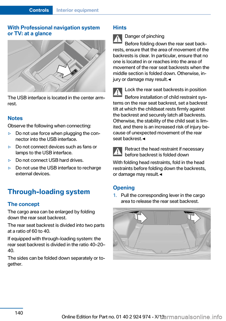
The USB interface is located in the center arm‐
rest.
Notes Observe the following when connecting:
▷Do not use force when plugging the con‐
nector into the USB interface.▷Do not connect devices such as fans or
lamps to the USB interface.▷Do not connect USB hard drives.▷Do not use the USB interface to recharge
external devices.
Through-loading system
The concept The cargo area can be enlarged by folding
down the rear seat backrest.
The rear seat backrest is divided into two parts at a ratio of 60 to 40.
If equipped with through-loading system: the
rear seat backrest is divided in the ratio 40–20– 40.
The sides can be folded down separately or to‐
gether.
Hints
Danger of pinching
Before folding down the rear seat back‐
rests, ensure that the area of movement of the
backrests is clear. In particular, ensure that no
one is located in or reaches into the area of
movement of the rear seat backrests when the
middle section is folded down. Otherwise, in‐
jury or damage may result.◀
Lock the rear seat backrests in position
Before installation of child restraint sys‐
tems on the rear seat backrest, set a backrest
tilt at which the childseat rests firmly against
the backrest and securely latch all backrests.
Otherwise, the stability of the child seat is lim‐
ited, and there is an increased risk of injury be‐
cause of unexpected movement of the rear
seat backrest.◀
Retract the head restraint if necessary
before backrest is folded down
With folding head restraints, fold in the head
restraints before folding down the backrests, or damage may result.◀
Opening1.Pull the corresponding lever in the cargo
area to release the rear seat backrest.Seite 140ControlsInterior equipment140
Online Edition for Part no. 01 40 2 924 974 - X/13
Page 143 of 218

LockingThe glove compartment can be locked with an
integrated key to separately secure the trunk
lid, refer to page 41, for example.
This prevents access to the glove compart‐
ment and to the cargo area.
After the glove compartment is locked, the re‐
mote control can be handed over, such as at a
hotel, without the integrated key.
Driver's side
Note Close the glove compartment again im‐
mediately
Close the glove compartment immediately af‐
ter use while driving; otherwise, injury may oc‐
cur during accidents.◀
Opening
Pull the handle.
ClosingFold cover closed.
Compartments in the doors Do not stow any breakable objects
Do not store any breakable objects, e. g.
glass bottles, in the compartments, or there is
an increased risk of injury in the event of an ac‐
cident.◀
Front storage compartment
There is a storage compartment between the
front seats. Raise the lid to open it.
Center armrest
Front
A storage compartment is located in the center armrest between the front seats.
Opening
Fold the center armrest up.
Repositioning
Center armrest can be pushed forwards or
backwards. It engages in the end positions.
Connection for an external audio
device
.
Storage compartment in the
rear
Storage compartment is located in the rear
center console.
Seite 143Storage compartmentsControls143
Online Edition for Part no. 01 40 2 924 974 - X/13
Page 149 of 218
Hot exhaust systemHot exhaust system
High temperatures are generated in the
exhaust system.
Do not remove the heat shields installed and
never apply undercoating to them. Make sure
that flammable materials, e. g. hay, leaves,
grass, etc. do not come in contact with the hot
exhaust system during driving, while in idle po‐
sition mode, or when parked. Such contact
could lead to a fire, and with it the risk of seri‐
ous personal injury as well as property dam‐
age.
Do not touch hot exhaust pipes; otherwise,
there is the danger of getting burned.◀
Mobile communication devices in the
vehicle
Mobile communication devices in the ve‐
hicle
It is advised that you do not use mobile com‐
munication devices, e.g., mobile phones, in‐
side the vehicle without connecting them di‐
rectly to the external antenna. Otherwise, the
vehicle electronics and mobile communication
devices can interfere with each other. In addi‐
tion, there is no assurance that the radiation
generated during transmission will be dis‐
charged from the vehicle interior.◀
Hydroplaning
On wet or slushy roads, a wedge of water can
form between the tires and road surface.
This phenomenon is referred to as hydroplan‐
ing. It is characterized by a partial or complete loss of contact between the tires and the road
surface, ultimately undermining your ability to
steer and brake the vehicle.
Hydroplaning
When driving on wet or slushy roads, re‐
duce your speed to prevent hydroplaning.◀Driving through water
Drive through calm water only and only if it is
not deeper than. 9.8 inches/25 cm and at this
height, no faster than walking speed, up to
6 mph/10 km/h.
Adhere to water depth and speed limita‐
tions
Do not exceed this water depth and walking speed; otherwise, the vehicle's engine, the
electrical systems and the transmission may
be damaged.◀
Braking safely
Your vehicle is equipped with ABS as a stand‐
ard feature.
Applying the brakes fully is the most effective
way of braking in situations when this is neces‐
sary.
The vehicle maintains steering responsive‐
ness. You can still avoid any obstacles with a
minimum of steering effort.
Pulsation of the brake pedal and sounds from
the hydraulic circuits indicate that ABS is in its
active mode.
Objects within the range of movement
of the pedals
No objects in the area around the pedals
Keep floor mats, carpets, and any other
objects out of the area of motion of the pedals;
otherwise, the function of the pedals could be
impeded while driving and create the risk of an
accident.
Do not place additional floor mats over existing
mats or other objects.
Only use floor mats that have been approved
for the vehicle and can be properly fixed in
place.
Ensure that the floor mats are securely fas‐
tened again after they were removed for clean‐
ing, for example.◀Seite 149Things to remember when drivingDriving tips149
Online Edition for Part no. 01 40 2 924 974 - X/13
Page 151 of 218
LoadingVehicle equipment
All standard, country-specific and optional
equipment that is offered in the model series is
described in this chapter. Therefore, equip‐
ment is also described that is not available in a
vehicle, e. g., because of the selected optional
equipment or country variant. This also applies
for safety-related functions and systems.
Hints Overloading the vehicle
To avoid exceeding the approved carry‐
ing capacity of the tires, never overload the ve‐
hicle. Overloading can lead to overheating and
increases the rate at which damage develops
inside the tires. This could result in a sudden
loss of tire inflation pressure.◀
No fluids in the trunk
Make sure that fluids do not leak into the
trunk; otherwise, the vehicle may be dam‐
aged.◀
Securing cargo
Always position and secure the cargo as
described above; otherwise, it can endanger
the car's occupants if sudden braking or
swerving becomes necessary.
Heavy or hard objects should not be carried
loose inside the car; otherwise, they could be
thrown around as a result of hard braking, sud‐
den swerves, etc., and endanger the occu‐
pants.◀
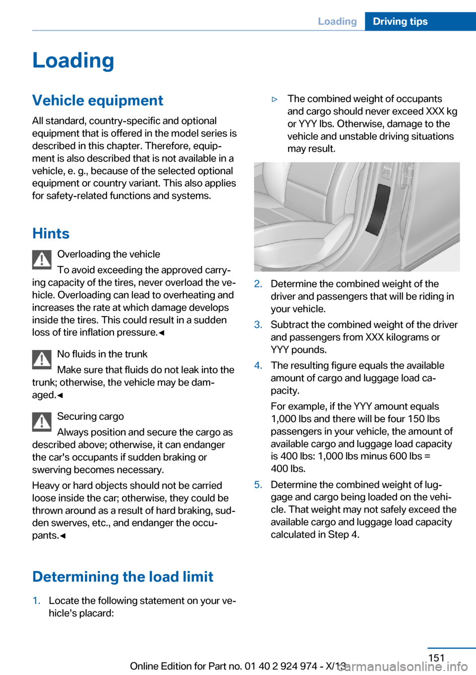
Determining the load limit1.Locate the following statement on your ve‐
hicle’s placard:▷The combined weight of occupants
and cargo should never exceed XXX kg
or YYY lbs. Otherwise, damage to the
vehicle and unstable driving situations
may result.2.Determine the combined weight of the
driver and passengers that will be riding in
your vehicle.3.Subtract the combined weight of the driver
and passengers from XXX kilograms or
YYY pounds.4.The resulting figure equals the available
amount of cargo and luggage load ca‐
pacity.
For example, if the YYY amount equals
1,000 lbs and there will be four 150 lbs
passengers in your vehicle, the amount of
available cargo and luggage load capacity
is 400 lbs: 1,000 lbs minus 600 lbs =
400 lbs.5.Determine the combined weight of lug‐
gage and cargo being loaded on the vehi‐
cle. That weight may not safely exceed the
available cargo and luggage load capacity
calculated in Step 4.Seite 151LoadingDriving tips151
Online Edition for Part no. 01 40 2 924 974 - X/13