2014 BMW M235I navigation system
[x] Cancel search: navigation systemPage 37 of 218

▷CD/Multimedia: audio source listened to
last.▷Unlocking/locking of the vehicle: settings.▷Driving Dynamics Control: sport program▷Driver's seat position: automatically re‐
trieved after unlocking.▷Programmable memory buttons: assign‐
ment.▷Headlamp courtesy delay feature: time set‐
ting.▷Tone: tone settings.▷Automatic climate control/Automatic cli‐
mate control with enhanced features: set‐
tings.▷Navigation: map views, route criteria, voice
output on/off.▷Park Distance Control PDC: adjusting the
signal tone volume.▷Radio: stored stations, station listened to
last, special settings.▷Rearview camera: selection of functions
and type of display.▷Language on the Control Display.▷Lane departure warning: last setting, on/
off.▷Daytime running lights: current setting.▷Triple turn signal activation.▷Locking the vehicle: after a brief period or
after starting to drive.
Central locking system
The concept The central locking system becomes active
when the driver's door is closed.
The system simultaneously engages and re‐
leases the locks on the following:
▷Doors.▷Trunk lid.▷Fuel filler flap.Operating from the outside▷Via the remote control.▷Via the door handles of the driver's and
front passenger doors.
The following takes place simultaneously
when locking/unlocking the vehicle via the re‐
mote control:
▷Depending on how the vehicle is equipped,
the theft protection is activated/deacti‐
vated. Theft protection prevents the doors
from being unlocked using the lock but‐
tons or the door opener.▷The welcome lamps, interior lamps and
courtesy lamps are switched on and off.▷The alarm system, refer to page 43, is
armed or disarmed.
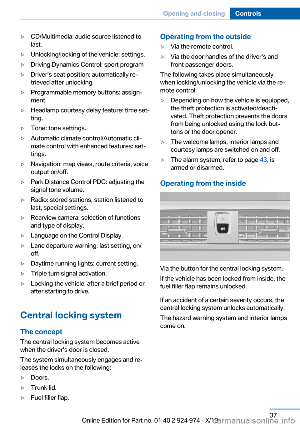
Operating from the inside
Via the button for the central locking system.
If the vehicle has been locked from inside, the
fuel filler flap remains unlocked.
If an accident of a certain severity occurs, the
central locking system unlocks automatically.
The hazard warning system and interior lamps
come on.
Seite 37Opening and closingControls37
Online Edition for Part no. 01 40 2 924 974 - X/13
Page 78 of 218

Overview, instrument cluster with enhanced features1Fuel gauge 802Miles/trip miles 80
External temperature 81
Time 81
Date 81
Selection list, e.g., radio 84
Service requirements 82
Navigation display, see user's manual for
Navigation, Entertainment and Communi‐
cation.Computer 85
Speed Limit Information 83
ECO PRO bonus range 1553Transmission display 73
Current fuel consumption 81
Energy recovery 824Messages, e.g. Check Control 785Navigation display, see user's manual for
Navigation, Entertainment and Communi‐
cation.Check Control
The concept The Check Control system monitors functions
in the vehicle and notifies you of malfunctions
in the monitored systems.
A Check Control message is displayed as a
combination of indicator or warning lamps and
text messages in the instrument cluster.In addition, an acoustic signal may be output
and a text message may appear on the Control
Display.
Indicator/warning lamps The indicator and warning lamps in the instru‐
ment cluster can light up in a variety of combi‐
nations and colors.
Several of the lamps are checked for proper
functioning and light up temporarily when the
engine is started or the ignition is switched on.Seite 78ControlsDisplays78
Online Edition for Part no. 01 40 2 924 974 - X/13
Page 83 of 218

Gear shift indicatorThe conceptThe system recommends the most fuel effi‐
cient gear for the current driving situation.
Depending on how the vehicle is equipped and
the country-specific version of the vehicle, the
gear shift indicator is active in the manual
mode of the automatic transmission and in the
manual transmission.
Indicators to shift up or down are displayed in
the instrument cluster.
On vehicles without a gear shift indicator, the
engaged gear is displayed.
Manual transmission: displaysSymbolDescriptionFuel efficient gear is engaged.Shift up to fuel efficient gear.Shift down to fuel efficient gear.Shift into neutral.
Automatic transmission: displays
ExampleDescriptionFuel efficient gear is engaged.Shift into fuel efficient gear.Speed limit detection with
No Passing Information
The concept
Speed limit detection Speed limit detection uses a symbol in the
shape of a traffic sign to display the currently
detected speed limit. The camera at the base
of the interior rearview mirror detects traffic
signs at the edge of the road as well as variable
overhead sign posts. Traffic signs with extra
symbols for wet road conditions, etc. are also
detected and compared with vehicle interior
data, such as for the rain sensor, and are dis‐
played depending on the situation. The system
takes into account the information stored in
the navigation system and also displays speed
limits present on routes without signs.
No Passing Information No Passing Information in the instrument clus‐
ter displays the beginnings and ends of no
passing zones detected by the camera. The
system accounts for only the beginnings and
ends of No Passing zones marked by signs.
No display is shown:▷In countries where No Passing zones are
primarily identified with road markings.▷On routes without signage.▷Where there are railroad crossings, high‐
way markings or other situations where no
signage is present, but passing would not
be permitted.
Hints
Personal judgment
The system cannot serve as a substitute
for the driver's personal judgment of the traffic
situation.
The system assists the driver and does not re‐
place the human eye.◀
Seite 83DisplaysControls83
Online Edition for Part no. 01 40 2 924 974 - X/13
Page 84 of 218

At a glance
Camera
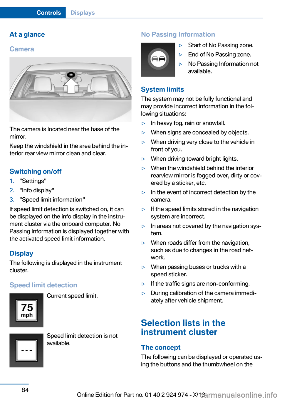
The camera is located near the base of the
mirror.
Keep the windshield in the area behind the in‐
terior rear view mirror clean and clear.
Switching on/off
1."Settings"2."Info display"3."Speed limit information"
If speed limit detection is switched on, it can
be displayed on the info display in the instru‐
ment cluster via the onboard computer. No
Passing Information is displayed together with
the activated speed limit information.
Display The following is displayed in the instrument
cluster.
Speed limit detection Current speed limit.
Speed limit detection is not available.
No Passing Information▷Start of No Passing zone.▷End of No Passing zone.▷No Passing Information not
available.
System limits
The system may not be fully functional and
may provide incorrect information in the fol‐
lowing situations:
▷In heavy fog, rain or snowfall.▷When signs are concealed by objects.▷When driving very close to the vehicle in
front of you.▷When driving toward bright lights.▷When the windshield behind the interior
rearview mirror is fogged over, dirty or cov‐
ered by a sticker, etc.▷In the event of incorrect detection by the
camera.▷If the speed limits stored in the navigation
system are incorrect.▷In areas not covered by the navigation sys‐
tem.▷When roads differ from the navigation,
such as due to changes in the road net‐
work.▷When passing buses or trucks with a
speed sticker.▷If the traffic signs are non-conforming.▷During calibration of the camera immedi‐
ately after vehicle shipment.
Selection lists in the
instrument cluster
The concept The following can be displayed or operated us‐
ing the buttons and the thumbwheel on the
Seite 84ControlsDisplays84
Online Edition for Part no. 01 40 2 924 974 - X/13
Page 86 of 218

Information at a glance
Info display Repeatedly pressing the button
on the turn signal lever calls up
the following information on the
info display:▷Range.▷ECO PRO bonus range.▷Average fuel consumption.▷Current fuel consumption.▷Average speed.▷Date.▷Speed limit detection.▷Time of arrival.
When destination guidance is activated in
the navigation system.▷Distance to destination.
When destination guidance is activated in
the navigation system.▷Arrow view of navigation system.
When destination guidance is activated in
the navigation system.
Adjusting the info display
You can select what information from the on‐
board computer is to be displayed on the info
display of the instrument cluster.
1."Settings"2."Info display"3.Select the desired displays.
Information in detail
Range
Displays the estimated cruising range available
with the remaining fuel.
It is calculated based on your driving style over
the last 20 miles/30 km.
Average fuel consumption
The average fuel consumption is calculated for
the period during which the engine is running.
The average fuel consumption is calculated for
the distance traveled since the last reset by the
onboard computer.
Average speed
Periods in which the vehicle is parked with the
engine manually stopped do not enter into the
calculation of the average speed.
Resetting average values
Press and hold the computer button on the
turn signal lever.
Distance to destination
The distance remaining to the destination is
displayed if a destination is entered in the navi‐
gation system before the trip is started.
The distance to the destination is adopted au‐
tomatically.
Time of arrival The estimated time of arrival is
displayed if a destination is en‐
tered in the navigation system
before the trip is started.
The time must be correctly set. Speed limit detection
Description of the speed limit detection, refer
to page 83, function.
Speed limit
Display of a speed limit which, when reached, should cause a warning to be issued.
The warning is repeated if the vehicle speed
drops below the set speed limit once by at
least 3 mph/5 km/h.Seite 86ControlsDisplays86
Online Edition for Part no. 01 40 2 924 974 - X/13
Page 118 of 218

At a glance
Button in the vehicle
PDC Park Distance Control
Switching on/off
Switching on automatically Select transmission position R with the engine
running.
Automatic deactivation during forward
travel
The system switches off when a certain driving
distance or speed is exceeded.
Switch the system back on if necessary.
Switching on/off manually Press the button.
▷On: the LED lights up.▷Off: the LED goes out.
In addition to the PDC Park Distance Control,
the rearview camera, refer to page 119, can be
switched on.
Switching on the rearview camera viathe iDrive
With PDC activated:
"Rear view camera"
The rearview camera image is displayed. The
setting is stored for the remote control cur‐
rently in use.
Display
Signal tones When approaching an object, an intermittent
tone is sounded that indicates the position of
the object. For example, if an object is de‐
tected to the left rear of the vehicle, a signal
tone sounds from the left rear speaker.
The shorter the distance to the object be‐
comes, the shorter the intervals.
If the distance to a detected object is less than
approx. 10 in/25 cm, a continuous tone is
sounded.
If objects are located both in front of and be‐
hind the vehicle, an alternating continuous sig‐
nal is sounded.
The signal tone is switched off:▷When the vehicle moves away from an ob‐
ject by more than approx. 4 in/10 cm.▷When transmission position P is engaged.
Volume
The volume of the PDC signal can be adjusted,
refer to user's manual for Navigation, Enter‐
tainment, Communication.
The setting is stored for the remote control
currently in use.
Visual warning
The approach of the vehicle to an object can
be shown on the Control Display. Objects that
are farther away are displayed on the Control
Display before a signal tone sounds.
A display appears as soon as Park Distance
Control (PDC) is activated.
The range of the sensors is represented in the
colors red, green and yellow.
If the rearview camera image was selected last,
it again appears on the display. To switch to
PDC:
1. "Rear view camera" Select the symbol
on the Control Display.Seite 118ControlsDriving comfort118
Online Edition for Part no. 01 40 2 924 974 - X/13
Page 139 of 218

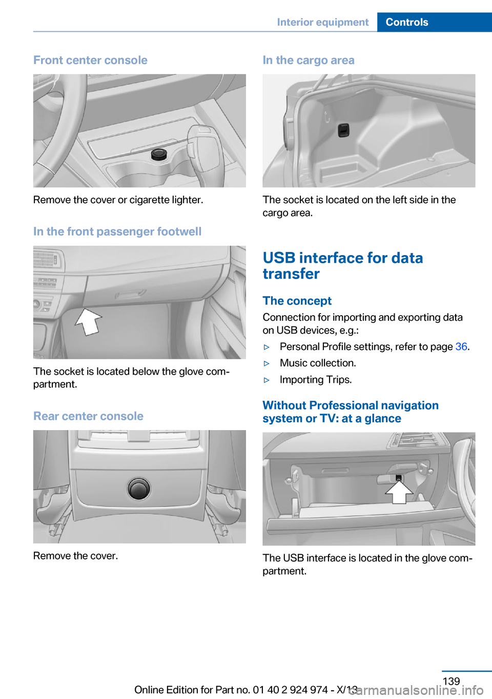
Front center console
Remove the cover or cigarette lighter.
In the front passenger footwell
The socket is located below the glove com‐
partment.
Rear center console
Remove the cover.
In the cargo area
The socket is located on the left side in the
cargo area.
USB interface for data
transfer
The concept Connection for importing and exporting data
on USB devices, e.g.:
▷Personal Profile settings, refer to page 36.▷Music collection.▷Importing Trips.
Without Professional navigation
system or TV: at a glance
The USB interface is located in the glove com‐
partment.
Seite 139Interior equipmentControls139
Online Edition for Part no. 01 40 2 924 974 - X/13
Page 140 of 218

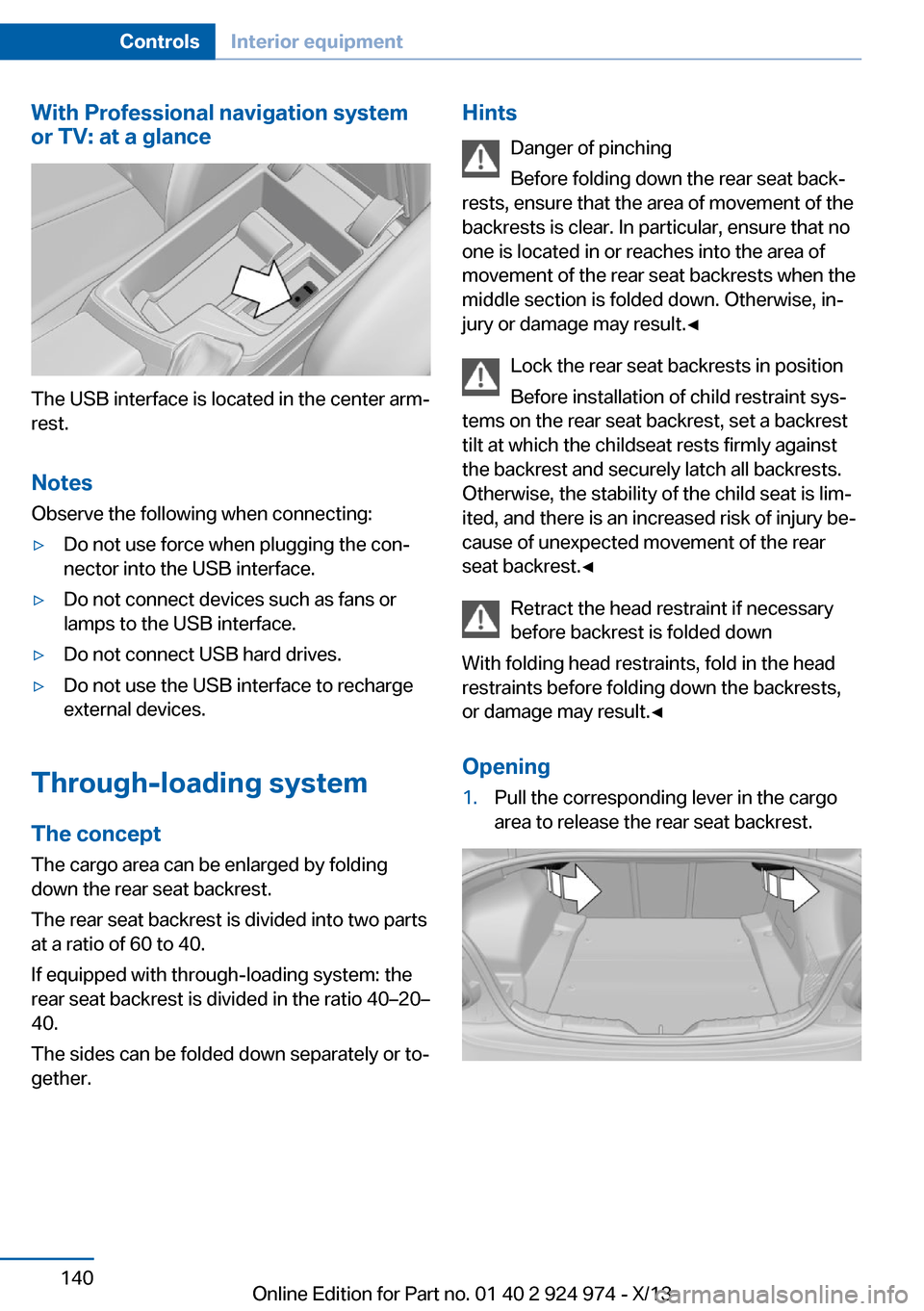
With Professional navigation system
or TV: at a glance
The USB interface is located in the center arm‐
rest.
Notes Observe the following when connecting:
▷Do not use force when plugging the con‐
nector into the USB interface.▷Do not connect devices such as fans or
lamps to the USB interface.▷Do not connect USB hard drives.▷Do not use the USB interface to recharge
external devices.
Through-loading system
The concept The cargo area can be enlarged by folding
down the rear seat backrest.
The rear seat backrest is divided into two parts at a ratio of 60 to 40.
If equipped with through-loading system: the
rear seat backrest is divided in the ratio 40–20– 40.
The sides can be folded down separately or to‐
gether.
Hints
Danger of pinching
Before folding down the rear seat back‐
rests, ensure that the area of movement of the
backrests is clear. In particular, ensure that no
one is located in or reaches into the area of
movement of the rear seat backrests when the
middle section is folded down. Otherwise, in‐
jury or damage may result.◀
Lock the rear seat backrests in position
Before installation of child restraint sys‐
tems on the rear seat backrest, set a backrest
tilt at which the childseat rests firmly against
the backrest and securely latch all backrests.
Otherwise, the stability of the child seat is lim‐
ited, and there is an increased risk of injury be‐
cause of unexpected movement of the rear
seat backrest.◀
Retract the head restraint if necessary
before backrest is folded down
With folding head restraints, fold in the head
restraints before folding down the backrests, or damage may result.◀
Opening1.Pull the corresponding lever in the cargo
area to release the rear seat backrest.Seite 140ControlsInterior equipment140
Online Edition for Part no. 01 40 2 924 974 - X/13