2014 BMW 740LI tow
[x] Cancel search: towPage 163 of 251
Switching on1.Switch off the ignition.2. Press the right side of the button
on the driver's side.
The symbol appears on the automatic cli‐
mate Control Display.
The interior temperature, air volume and air
distribution can be adjusted with the ignition
switched on.
Switching off
At the lowest fan speed, press the left side of
the button on the driver's side.
The symbol on the display of the automatic
climate control flashes.
Switching the system on/off Switching off
▷Complete system: Press and hold the left button on
the driver's side until the control
clicks off.▷On the front passenger side:
Press and hold the left button on
the front passenger side.
Switching on
Press any button except:
▷SYNC program.▷Rear window defroster.▷Left side of Air volume button.▷Seat heating.▷Seat ventilation.
Microfilter/activated-charcoal filter
The microfilter removes dust and pollen from
the incoming air.
The activated-charcoal filter removes gaseous
pollutants from the outside air that enters the
vehicle.
This combined filter should be replaced during
scheduled maintenance, refer to page 216, of
your vehicle.
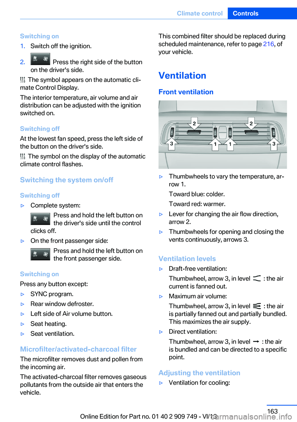
Ventilation Front ventilation▷Thumbwheels to vary the temperature, ar‐
row 1.
Toward blue: colder.
Toward red: warmer.▷Lever for changing the air flow direction,
arrow 2.▷Thumbwheels for opening and closing the
vents continuously, arrows 3.
Ventilation levels
▷Draft-free ventilation:
Thumbwheel, arrow 3, in level
: the air
current is fanned out.
▷Maximum air volume:
Thumbwheel, arrow 3, in level
: the air
is partially fanned out and partially bundled.
This maximizes the air supply.
▷Direct ventilation:
Thumbwheel, arrow 3, in level
: the air
is bundled and can be directed to a specific
point.
Adjusting the ventilation
▷Ventilation for cooling:Seite 163Climate controlControls163
Online Edition for Part no. 01 40 2 909 749 - VI/13
Page 164 of 251
Adjust the vent to direct the air in your di‐
rection, e.g., if the vehicle interior is hot
from the sun.▷Draft-free ventilation:
Adjust the vent to let the air flow past you.
Ventilation in rear, center
▷Thumbwheels to vary the temperature, ar‐
row 1.
Toward blue: colder.
Toward red: warmer.▷Lever for changing the air flow direction,
arrow 2.▷Thumbwheels for continuous opening and
closing of the vents, arrow 3.
Lateral ventilation
▷Thumbwheel for opening and closing the
vents continuously, arrow 1.▷Lever for changing the air flow direction,
arrow 2.Rear automatic climate
control
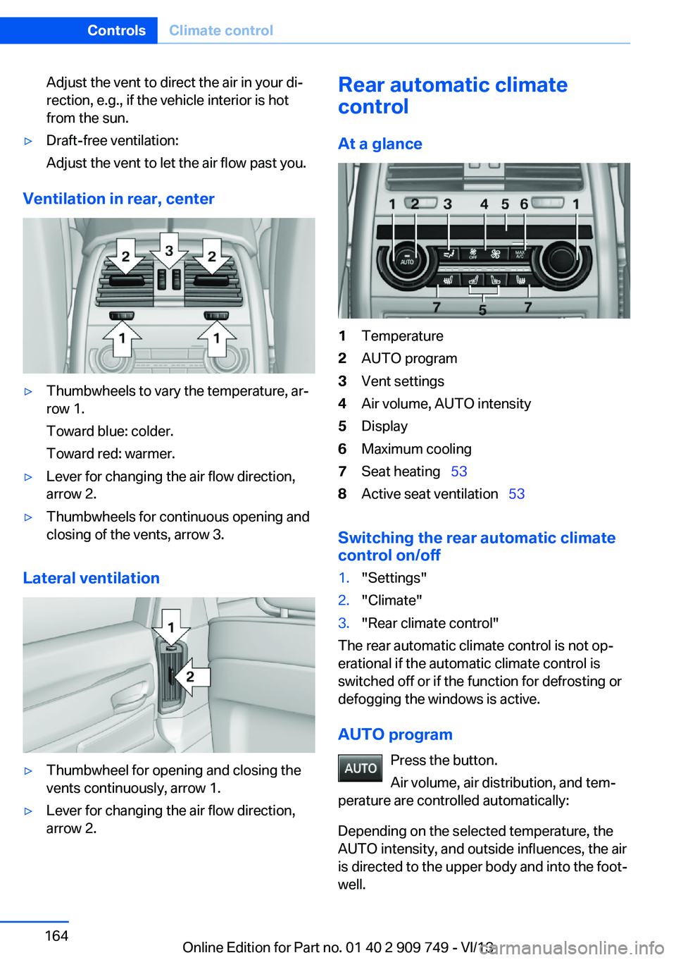
At a glance1Temperature2AUTO program3Vent settings4Air volume, AUTO intensity5Display6Maximum cooling7Seat heating 538Active seat ventilation 53
Switching the rear automatic climate
control on/off
1."Settings"2."Climate"3."Rear climate control"
The rear automatic climate control is not op‐
erational if the automatic climate control is
switched off or if the function for defrosting or
defogging the windows is active.
AUTO program Press the button.
Air volume, air distribution, and tem‐
perature are controlled automatically:
Depending on the selected temperature, the
AUTO intensity, and outside influences, the air
is directed to the upper body and into the foot‐
well.
Seite 164ControlsClimate control164
Online Edition for Part no. 01 40 2 909 749 - VI/13
Page 176 of 251
Storage compartmentsVehicle equipmentAll standard, country-specific and optional
equipment that is offered in the model series is
described in this chapter. Therefore, equip‐
ment is also described that is not available in a
vehicle, e. g., because of the selected optional
equipment or country variant. This also applies
for safety-related functions and systems.
Notes No loose objects in the passenger com‐
partment
Do not stow any objects in the passenger
compartment without securing them; other‐
wise, they may present a danger to occupants
for instance during braking and avoidance ma‐
neuvers.◀
Do not place anti-slip mats on the dash‐
board
Do not place anti-slip mats on the dashboard.
The mat materials could damage the dash‐
board.◀
Storage compartments
The following storage compartments are avail‐
able in the vehicle interior:▷Glove compartment on the driver's and
front passenger side, refer to page 176.▷Storage compartment in the center arm‐
rest, refer to page 177, in the front and
rear.▷Compartments in the doors.▷Pockets on the backrests of the front
seats.▷Net in the front passenger footwell.Glove compartment
Front passenger side
Note Close the glove compartment again im‐
mediately
Close the glove compartment immediately af‐
ter use while driving; otherwise, injury may oc‐
cur during accidents.◀
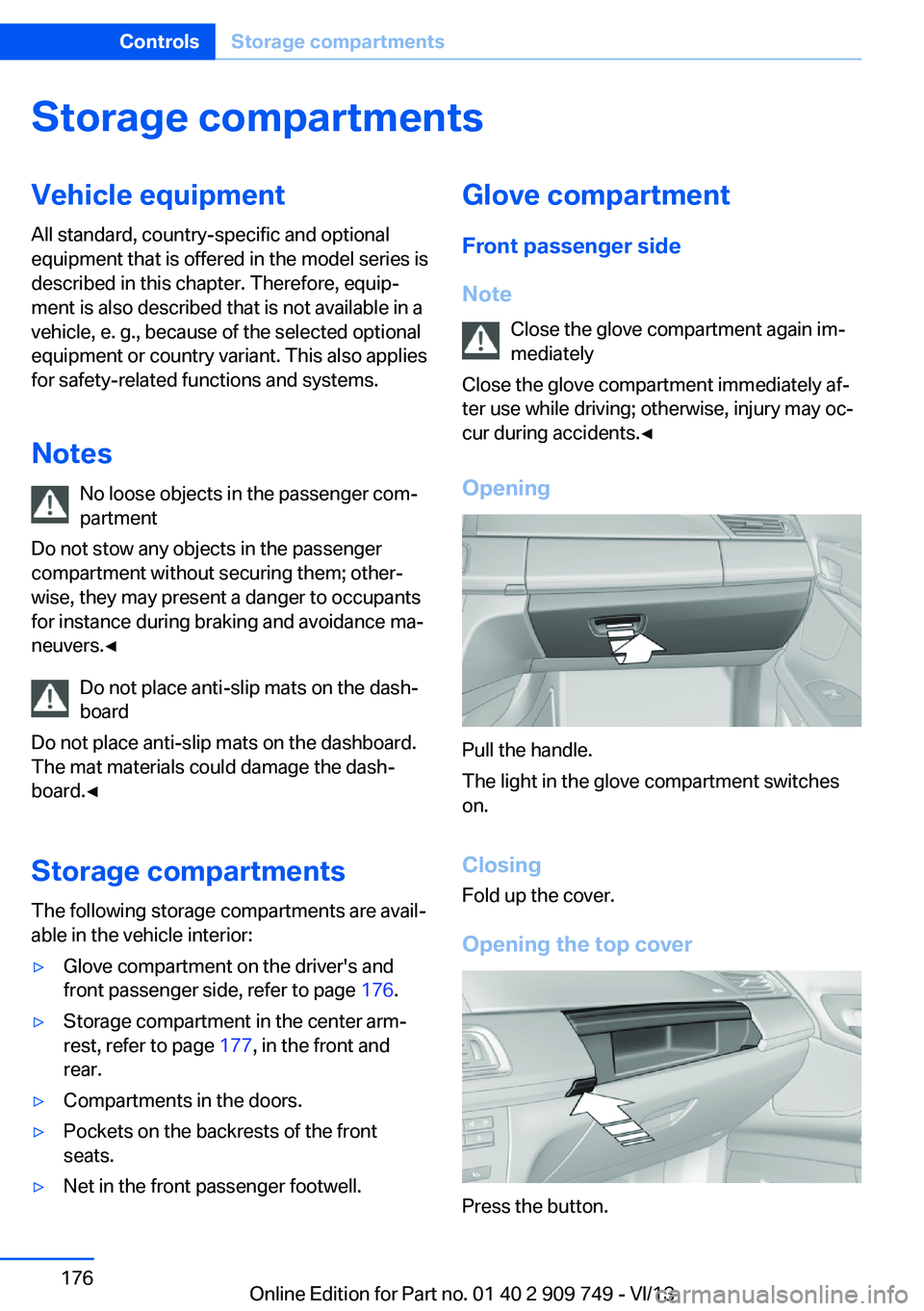
Opening
Pull the handle.
The light in the glove compartment switches
on.
ClosingFold up the cover.
Opening the top cover
Press the button.
Seite 176ControlsStorage compartments176
Online Edition for Part no. 01 40 2 909 749 - VI/13
Page 186 of 251
Stowing cargo▷Cover sharp edges and corners on the
cargo.▷Heavy cargo: stow as far forward as possi‐
ble, directly behind and at the bottom of
the rear passenger seat backrests.▷Very heavy cargo: when the rear seat is not
occupied, secure each of the outer safety
belts in the opposite buckle.
Securing cargo
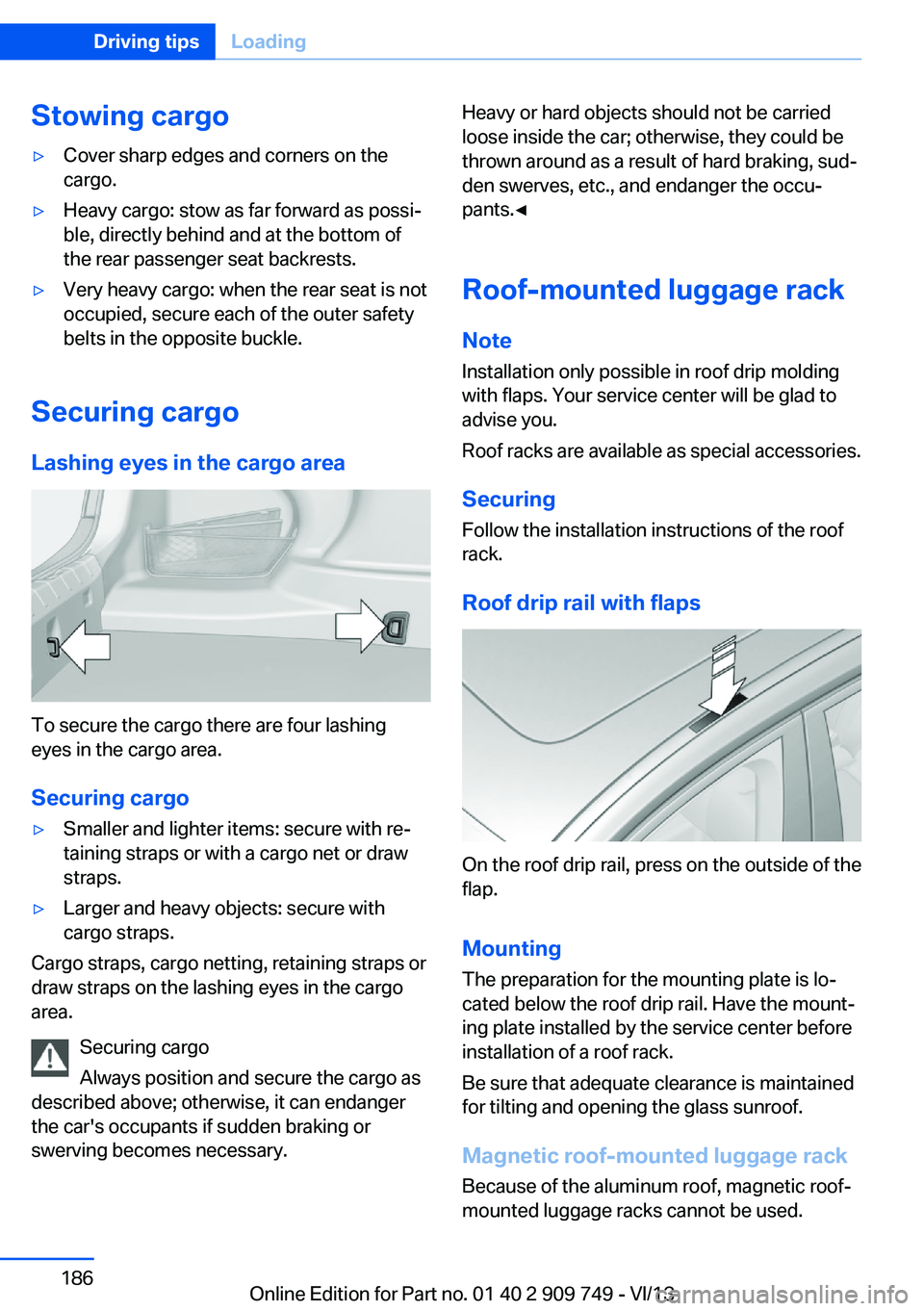
Lashing eyes in the cargo area
To secure the cargo there are four lashing
eyes in the cargo area.
Securing cargo
▷Smaller and lighter items: secure with re‐
taining straps or with a cargo net or draw
straps.▷Larger and heavy objects: secure with
cargo straps.
Cargo straps, cargo netting, retaining straps or
draw straps on the lashing eyes in the cargo
area.
Securing cargo
Always position and secure the cargo as
described above; otherwise, it can endanger
the car's occupants if sudden braking or
swerving becomes necessary.
Heavy or hard objects should not be carried
loose inside the car; otherwise, they could be
thrown around as a result of hard braking, sud‐
den swerves, etc., and endanger the occu‐
pants.◀
Roof-mounted luggage rack
Note Installation only possible in roof drip moldingwith flaps. Your service center will be glad to
advise you.
Roof racks are available as special accessories.
Securing
Follow the installation instructions of the roof
rack.
Roof drip rail with flaps
On the roof drip rail, press on the outside of the
flap.
Mounting
The preparation for the mounting plate is lo‐
cated below the roof drip rail. Have the mount‐
ing plate installed by the service center before
installation of a roof rack.
Be sure that adequate clearance is maintained
for tilting and opening the glass sunroof.
Magnetic roof-mounted luggage rack Because of the aluminum roof, magnetic roof-
mounted luggage racks cannot be used.
Seite 186Driving tipsLoading186
Online Edition for Part no. 01 40 2 909 749 - VI/13
Page 205 of 251
xxxx: manufacturer code for the tire brand
xxx: tire size and tire design
1013: tire age
Tires with DOT codes meet the guidelines of
the U.S. Department of Transportation.
Tire age DOT … 1013: the tire was manufactured in the
10th week 2013.
Recommendation
Regardless of wear, replace tires at least every
6 years.
Uniform Tire Quality Grading
Quality grades can be found where applicable
on the tire sidewall between tread shoulder
and maximum section width.
For example: Treadwear 200; Traction AA;
Temperature A
DOT Quality Grades Treadwear
Traction AA A B C
Temperature A B C
All passenger car tires must conform to Fed‐
eral Safety Requirements in addition to these
grades.
Treadwear The treadwear grade is a comparative rating
based on the wear rate of the tire when tested
under controlled conditions on a specified gov‐
ernment test course. For example, a tire graded 150 would wear one and one-half, 1 g,times as well on the government course as a
tire graded 100. The relative performance of
tires depends upon the actual conditions of
their use, however, and may depart signifi‐
cantly from the norm due to variations in driv‐
ing habits, service practices and differences in
road characteristics and climate.Traction
The traction grades, from highest to lowest,
are AA, A, B, and C.
Those grades represent the tire's ability to
stop on wet pavement as measured under
controlled conditions on specified government
test surfaces of asphalt and concrete. A tire
marked C may have poor traction performance.
The traction grade assigned to this tire is
based on straight-ahead braking traction tests,
and does not include acceleration, cornering,
hydroplaning, or peak traction characteristics.
Temperature
The temperature grades are A, the highest, B,
and C, representing the tire's resistance to the
generation of heat and its ability to dissipate
heat when tested under controlled conditions
on a specified indoor laboratory test wheel.
Sustained high temperature can cause the ma‐
terial of the tire to degenerate and reduce tire
life, and excessive temperature can lead to
sudden tire failure. The grade C corresponds
to a level of performance which all passenger
car tires must meet under the Federal Motor
Vehicle Safety Standard No. 109. Grades Band
A represent higher levels of performance on
the laboratory test wheel than the minimum re‐
quired by law.
Temperature grade for this tire
The temperature grade for this tire is es‐
tablished for a tire that is properly inflated and
not overloaded. Excessive speed, underinfla‐
tion, or excessive loading, either separately or
in combination, can cause heat buildup and
possible tire failure.
If necessary, have the vehicle towed.◀
RSC – Run-flat tires
Run-flat tires, refer to page 208, are labeled
with a circular symbol containing the letters
RSC marked on the sidewall.Seite 205Wheels and tiresMobility205
Online Edition for Part no. 01 40 2 909 749 - VI/13
Page 206 of 251
M+S
Winter and all-season tires with better cold
weather performance than summer tires.
Tire tread Summer tires
Do not drive with a tire tread depth of less than
0.12 in/3 mm.
There is an increased danger of hydroplaning if
the tread depth is less than 0.12 in/3 mm.
Winter tires
Do not drive with a tire tread depth of less than
0.16 in/4 mm.
Below a tread depth of 0.16 in/4 mm, tires are
less suitable for winter operation.
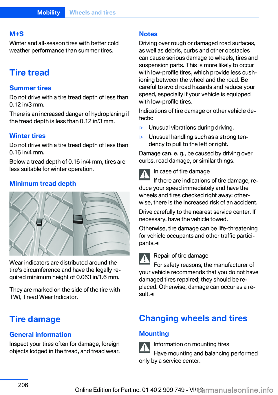
Minimum tread depth
Wear indicators are distributed around the
tire's circumference and have the legally re‐
quired minimum height of 0.063 in/1.6 mm.
They are marked on the side of the tire with
TWI, Tread Wear Indicator.
Tire damage
General information
Inspect your tires often for damage, foreign
objects lodged in the tread, and tread wear.
Notes
Driving over rough or damaged road surfaces,
as well as debris, curbs and other obstacles
can cause serious damage to wheels, tires and
suspension parts. This is more likely to occur
with low-profile tires, which provide less cush‐
ioning between the wheel and the road. Be
careful to avoid road hazards and reduce your
speed, especially if your vehicle is equipped
with low-profile tires.
Indications of tire damage or other vehicle de‐
fects:▷Unusual vibrations during driving.▷Unusual handling such as a strong ten‐
dency to pull to the left or right.
Damage can, e. g., be caused by driving over
curbs, road damage, or similar things.
In case of tire damage
If there are indications of tire damage, re‐
duce your speed immediately and have the
wheels and tires checked right away; other‐
wise, there is the increased risk of an accident.
Drive carefully to the nearest service center. If
necessary, have the vehicle towed.
Otherwise, tire damage can be life-threatening
for vehicle occupants and other traffic partici‐
pants.◀
Repair of tire damage
For safety reasons, the manufacturer of
your vehicle recommends that you do not have
damaged tires repaired; they should be re‐
placed. Otherwise, damage can occur as a re‐
sult.◀
Changing wheels and tires
Mounting Information on mounting tires
Have mounting and balancing performed
only by a service center.
Seite 206MobilityWheels and tires206
Online Edition for Part no. 01 40 2 909 749 - VI/13
Page 215 of 251
CoolantVehicle equipmentAll standard, country-specific and optional
equipment that is offered in the model series is
described in this chapter. Therefore, equip‐
ment is also described that is not available in a
vehicle, e. g., because of the selected optional
equipment or country variant. This also applies
for safety-related functions and systems.
General information Danger of burns from hot engine
Do not open the cooling system while
the engine is hot; otherwise, escaping coolant may cause burns.◀
Suitable additives
Only use suitable additives; otherwise,
engine damage may occur. The additives are
harmful to your health.◀
Coolant consists of water and additives.
Not all commercially available additives are
suitable for your vehicle. Ask your service cen‐
ter for suitable additives.
Coolant level
If there is no Min. and Max. mark in the filler
neck of the coolant reservoir, have the coolant
level checked if necessary by your service cen‐
ter and add coolant as needed.
Note Depending on the engine installation, the cool‐
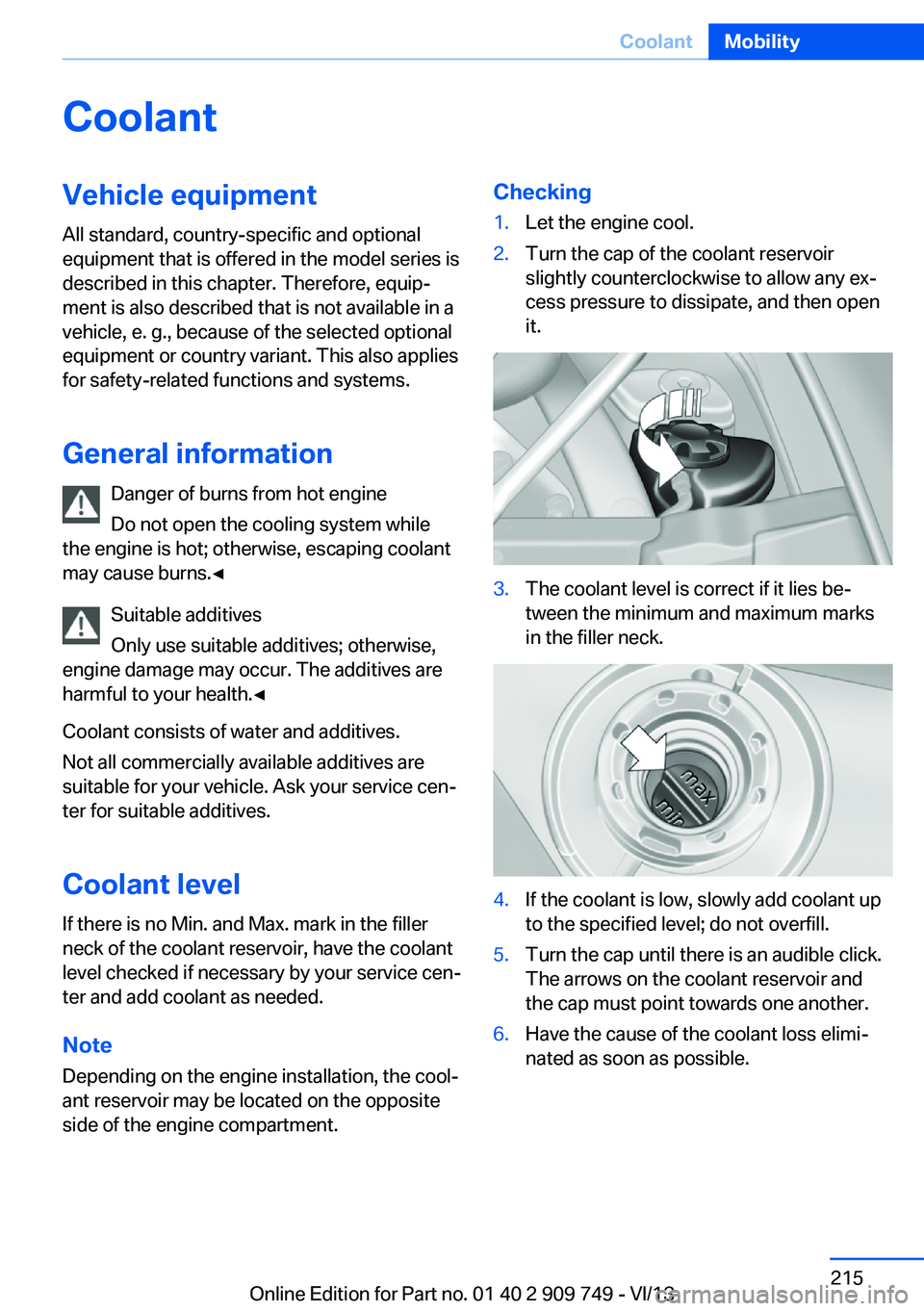
ant reservoir may be located on the opposite side of the engine compartment.Checking1.Let the engine cool.2.Turn the cap of the coolant reservoir
slightly counterclockwise to allow any ex‐
cess pressure to dissipate, and then open
it.3.The coolant level is correct if it lies be‐
tween the minimum and maximum marks
in the filler neck.4.If the coolant is low, slowly add coolant up
to the specified level; do not overfill.5.Turn the cap until there is an audible click.
The arrows on the coolant reservoir and
the cap must point towards one another.6.Have the cause of the coolant loss elimi‐
nated as soon as possible.Seite 215CoolantMobility215
Online Edition for Part no. 01 40 2 909 749 - VI/13
Page 218 of 251
Replacing componentsVehicle equipmentAll standard, country-specific and optional
equipment that is offered in the model series is
described in this chapter. Therefore, equip‐
ment is also described that is not available in a
vehicle, e. g., because of the selected optional
equipment or country variant. This also applies
for safety-related functions and systems.
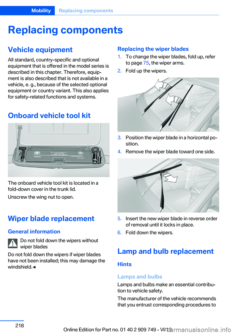
Onboard vehicle tool kit
The onboard vehicle tool kit is located in a
fold-down cover in the trunk lid.
Unscrew the wing nut to open.
Wiper blade replacement
General information Do not fold down the wipers without
wiper blades
Do not fold down the wipers if wiper blades
have not been installed; this may damage the
windshield.◀
Replacing the wiper blades1.To change the wiper blades, fold up, refer
to page 75, the wiper arms.2.Fold up the wipers.3.Position the wiper blade in a horizontal po‐
sition.4.Remove the wiper blade toward one side.5.Insert the new wiper blade in reverse order
of removal until it locks in place.6.Fold down the wipers.
Lamp and bulb replacement
Hints
Lamps and bulbs
Lamps and bulbs make an essential contribu‐
tion to vehicle safety.
The manufacturer of the vehicle recommends
that you entrust corresponding procedures to
Seite 218MobilityReplacing components218
Online Edition for Part no. 01 40 2 909 749 - VI/13