Page 75 of 243

▷Shift up: pull right shift paddle.▷Shift down: pull left shift paddle.
Gears will only be shifted at appropriate engine
and road speeds, e.g., downshifting is not pos‐
sible if the engine speed is too high.
The selected gear is briefly displayed in the in‐
strument cluster, followed by the current gear.
Shift lights in the instrument display
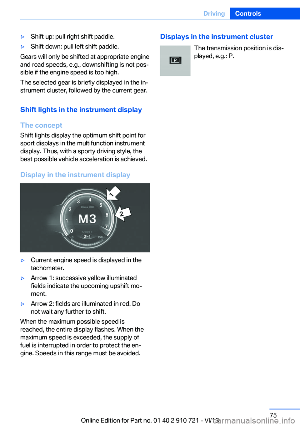
The concept Shift lights display the optimum shift point for
sport displays in the multifunction instrument
display. Thus, with a sporty driving style, the
best possible vehicle acceleration is achieved.
Display in the instrument display
▷Current engine speed is displayed in the
tachometer.▷Arrow 1: successive yellow illuminated
fields indicate the upcoming upshift mo‐
ment.▷Arrow 2: fields are illuminated in red. Do
not wait any further to shift.
When the maximum possible speed is
reached, the entire display flashes. When the
maximum speed is exceeded, the supply of
fuel is interrupted in order to protect the en‐
gine. Speeds in this range must be avoided.
Displays in the instrument cluster
The transmission position is dis‐
played, e.g.: P.Seite 75DrivingControls75
Online Edition for Part no. 01 40 2 910 721 - VI/13
Page 76 of 243
DisplaysVehicle equipmentAll standard, country-specific and optional
equipment that is offered in the model series is
described in this chapter. Therefore, equip‐ment is also described that is not available in a
vehicle, e. g., because of the selected optional
equipment or country variant. This also applies
for safety-related functions and systems.
Instrument cluster
1Fuel gauge 822Speedometer3Indicator/warning lamps 804Tachometer 825Oil temperature 826Electronic displays 777Reset miles 83Seite 76ControlsDisplays76
Online Edition for Part no. 01 40 2 910 721 - VI/13
Page 77 of 243
Electronic displays
Overview, instrument cluster1Messages, e.g. Check Control 80
Time 832Range 833Computer 874Navigation display, see user's manual for
Navigation, Entertainment and Communi‐
cation.
Service requirements 84Miles/trip miles 835Selection list, e.g., radio 87
Current fuel consumption 84
Energy recovery 84
External temperature 83
Transmission display 75Multifunctional instrument
display
The concept The instrument dispaly is a variable display.
When the driving mode is changed, the ap‐pearance is changed to reflect the new driving
mode. The change of appearance can be de‐
activated in the Control Display.
Some of the displays in the instrument display
may differ from the way they are shown in this
owner's manual.Seite 77DisplaysControls77
Online Edition for Part no. 01 40 2 910 721 - VI/13
Page 78 of 243
At a glance1Fuel gauge 822Indicator/warning lamps 803Speedometer4Variable displays5Tachometer 82Selection lists 87
ECO PRO displays 1806Oil temperature 827Computer 878Reset miles 83
Switching the change of display on and off
You can set whether the instrument display
automatically changes to the ECO PRO or
SPORT in the display when you switch driving
modes.1."Settings"2."Info display"3."ECO PRO Info"
or"Driving mode view"With Professional Navigation System:
switching zoom function on/off
Switching
You can program whether the current speed is
to appear enlarged in the speedometer.1."Settings"2."Info display"3."Magnifier function"Seite 78ControlsDisplays78
Online Edition for Part no. 01 40 2 910 721 - VI/13
Page 79 of 243
ECO PRO displays1Speedometer2Variable displays: ECO PRO Tips, Deceler‐
ation assistant instructions, Driver assist
system displays3Efficiency display 1804Transmission display 755▷Blue: bonus range▷Gray: rangeIn ECO PRO driving mode, the instrument dis‐
play switches to the ECO PRO displays. These
displays support a driving style that saves onfuel consumption with more prominent repre‐
sentation of the efficiency display and various
ECO PRO tips.Seite 79DisplaysControls79
Online Edition for Part no. 01 40 2 910 721 - VI/13
Page 80 of 243

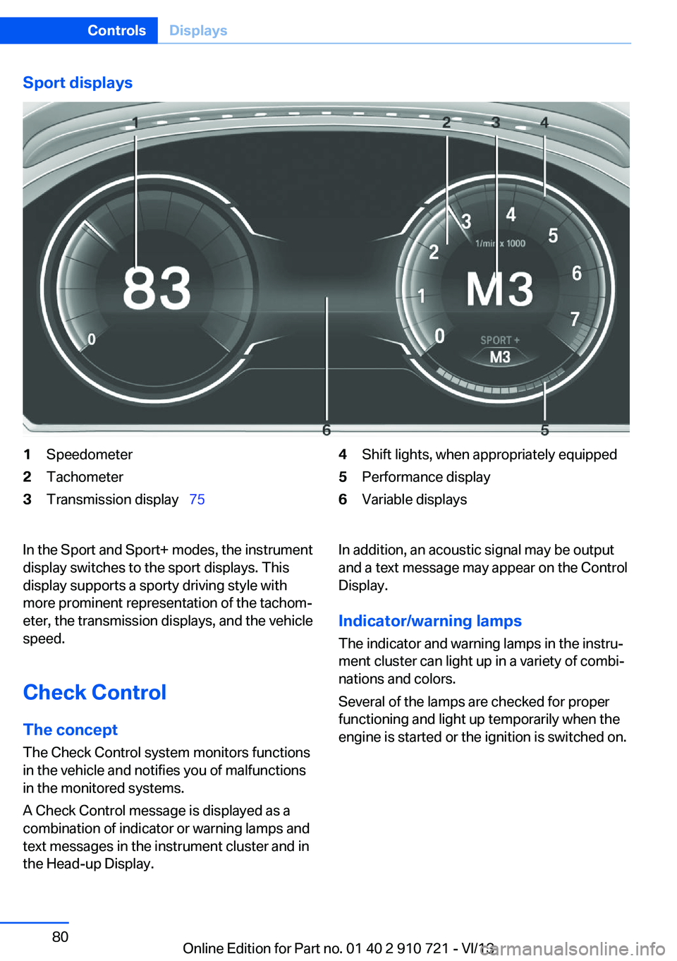
Sport displays1Speedometer2Tachometer3Transmission display 754Shift lights, when appropriately equipped5Performance display6Variable displaysIn the Sport and Sport+ modes, the instrument
display switches to the sport displays. This
display supports a sporty driving style with
more prominent representation of the tachom‐
eter, the transmission displays, and the vehicle
speed.
Check Control
The concept The Check Control system monitors functions
in the vehicle and notifies you of malfunctions
in the monitored systems.
A Check Control message is displayed as a
combination of indicator or warning lamps and
text messages in the instrument cluster and in
the Head-up Display.In addition, an acoustic signal may be output and a text message may appear on the Control
Display.
Indicator/warning lamps
The indicator and warning lamps in the instru‐
ment cluster can light up in a variety of combi‐
nations and colors.
Several of the lamps are checked for proper
functioning and light up temporarily when the
engine is started or the ignition is switched on.Seite 80ControlsDisplays80
Online Edition for Part no. 01 40 2 910 721 - VI/13
Page 81 of 243

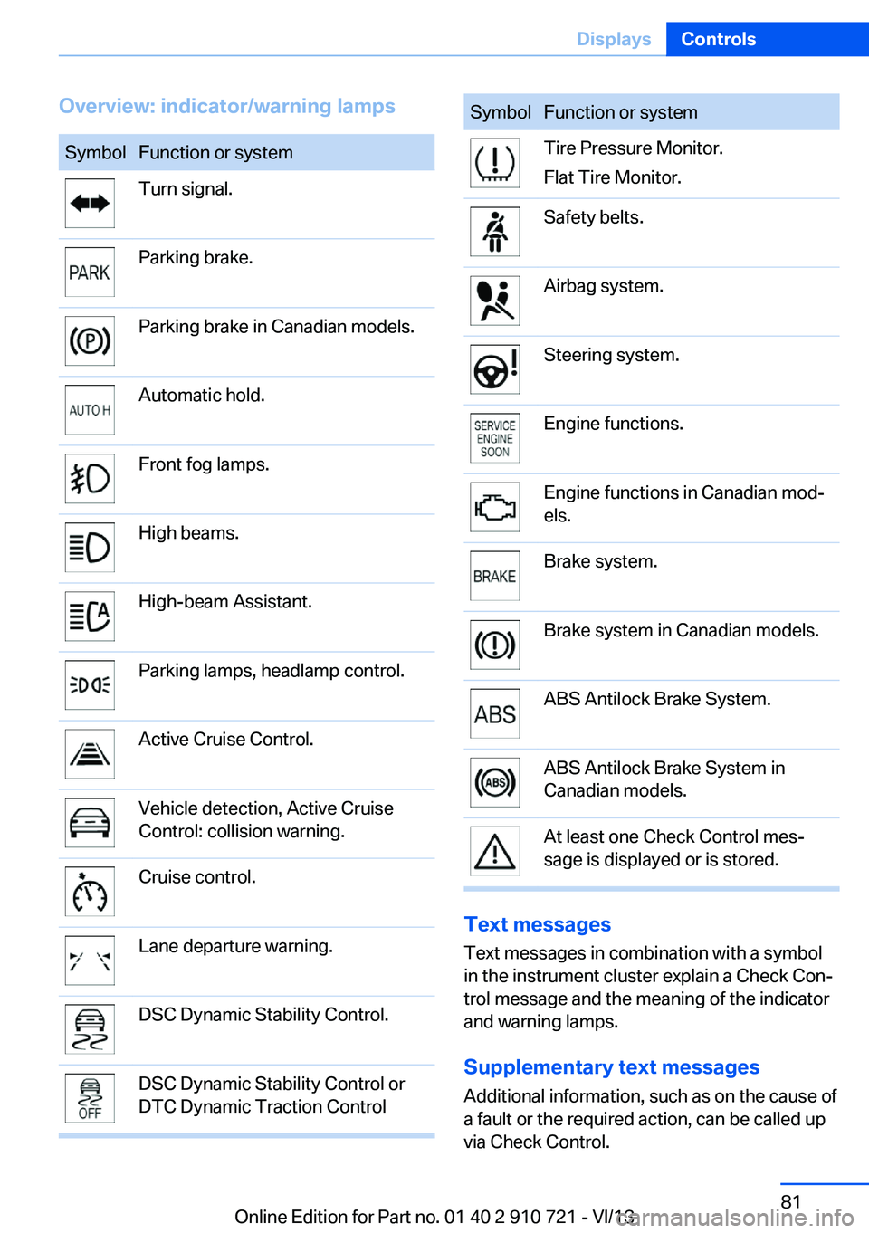
Overview: indicator/warning lampsSymbolFunction or systemTurn signal.Parking brake.Parking brake in Canadian models.Automatic hold.Front fog lamps.High beams.High-beam Assistant.Parking lamps, headlamp control.Active Cruise Control.Vehicle detection, Active Cruise
Control: collision warning.Cruise control.Lane departure warning.DSC Dynamic Stability Control.DSC Dynamic Stability Control or
DTC Dynamic Traction ControlSymbolFunction or systemTire Pressure Monitor.
Flat Tire Monitor.Safety belts.Airbag system.Steering system.Engine functions.Engine functions in Canadian mod‐
els.Brake system.Brake system in Canadian models.ABS Antilock Brake System.ABS Antilock Brake System in
Canadian models.At least one Check Control mes‐
sage is displayed or is stored.
Text messages
Text messages in combination with a symbol
in the instrument cluster explain a Check Con‐ trol message and the meaning of the indicator
and warning lamps.
Supplementary text messages
Additional information, such as on the cause of
a fault or the required action, can be called up
via Check Control.
Seite 81DisplaysControls81
Online Edition for Part no. 01 40 2 910 721 - VI/13
Page 82 of 243

The supplementary text of urgent messages is
automatically displayed on the Control Display.
Symbols
Depending on the Check Control message, the
following functions can be selected.▷ "Owner's Manual"
Display additional information about the
Check Control message in the Integrated
Owner's Manual.▷ "Service request"
Contact the service partner.▷ "Roadside Assistance"
Contact Roadside Assistance.
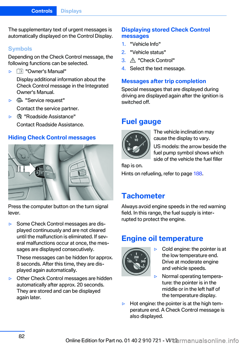
Hiding Check Control messages
Press the computer button on the turn signal
lever.
▷Some Check Control messages are dis‐
played continuously and are not cleared
until the malfunction is eliminated. If sev‐
eral malfunctions occur at once, the mes‐
sages are displayed consecutively.
These messages can be hidden for approx.
8 seconds. After this time, they are dis‐
played again automatically.▷Other Check Control messages are hidden
automatically after approx. 20 seconds.
They are stored and can be displayed
again later.Displaying stored Check Control
messages1."Vehicle Info"2."Vehicle status"3. "Check Control"4.Select the text message.
Messages after trip completion
Special messages that are displayed during
driving are displayed again after the ignition is
switched off.
Fuel gauge The vehicle inclination may
cause the display to vary.
US models: the arrow beside the
fuel pump symbol shows which
side of the vehicle the fuel filler
flap is on.
Hints on refueling, refer to page 188.
Tachometer
Always avoid engine speeds in the red warning
field. In this range, the fuel supply is inter‐
rupted to protect the engine.
Engine oil temperature
▷Cold engine: the pointer is at
the low temperature end.
Drive at moderate engine
and vehicle speeds.▷Normal operating tempera‐
ture: the pointer is in the
middle or in the left half of
the temperature display.▷Hot engine: the pointer is at the high tem‐
perature end. A Check Control message is
also displayed.Seite 82ControlsDisplays82
Online Edition for Part no. 01 40 2 910 721 - VI/13