2014 BMW 650I CONVERTIBLE parking brake
[x] Cancel search: parking brakePage 122 of 243
Driving stability control systemsVehicle equipmentAll standard, country-specific and optional
equipment that is offered in the model series is
described in this chapter. Therefore, equip‐
ment is also described that is not available in a
vehicle, e. g., because of the selected optional
equipment or country variant. This also applies
for safety-related functions and systems.
Antilock Brake System ABS ABS prevents locking of the wheels during
braking.
The vehicle remains steerable even during full
brake applications, thus increasing active
safety.
ABS is operational every time you start the en‐
gine.
Brake assistant
When you apply the brakes rapidly, this system
automatically produces the maximum braking
force boost. This then reduces braking dis‐ tance to a minimum during full braking. This
system utilizes all of the benefits provided by ABS.
Do not reduce the pressure on the brake pedal
for the duration of the full braking.
When equipped with Driving Assistant Plus or
with Active Cruise Control with Stop & Go
function, ACC is supported by the braking in‐
tervention if there is a possible risk of collision.
To do this, the braking force is automatically increased if the braking pressure is insufficient
when the brakes are applied.Adaptive brake assistant
In combination with the Active Cruise Control,
this system ensures that the brakes respond
even more rapidly when braking in critical sit‐
uations.
Drive-off assistant
This system supports driving away on gradi‐
ents. The parking brake is not required.1.Hold the vehicle in place with the foot
brake.2.Release the foot brake and drive away
without delay.
After the foot brake is released, the vehicle is
held in place for approx. 2 seconds.
Depending on the vehicle load, the vehicle may
roll back slightly.
Driving off without delay
After releasing the foot brake, start driv‐
ing without delay, since the drive-off assistant
will not hold the vehicle in place for more than
approx. 2 seconds and the vehicle will begin
rolling back.◀
DSC Dynamic Stability
Control
The concept DSC prevents traction loss in the driving
wheels when driving away and accelerating.
DSC also recognizes unstable vehicle condi‐
tions, such as fishtailing or nose-diving. Sub‐
ject to physical limits, DSC helps to keep the
vehicle on a steady course by reducing engine
speed and by applying brakes at individual
wheels.
Seite 122ControlsDriving stability control systems122
Online Edition for Part no. 01 40 2 910 721 - VI/13
Page 133 of 243
If active, the displayed speed is stored and the
vehicle reaches the stored speed if the road is
clear.▷Each time the rocker switch is pressed to
the point of resistance, the desired speed
increases or decreases by approx.
1 mph/1 km/h.▷Each time the rocker switch is pressed
past the point of resistance, the desired
speed increases or decreases by a maxi‐
mum of 5 mph/10 km/h.
Hold the rocker switch in position to repeat the
action.
Distance Selecting a distance
Adjust the distance according to the traf‐
fic and weather conditions; otherwise, there is
the danger of an accident occurring. Maintain
the prescribed safety distance.◀
Reduce distance Press the button repeatedly until the
desired distance is set.
The selected distance, refer to page 134, is
displayed in the instrument cluster.
Increase distance Press the button repeatedly until the
desired distance is set.
The selected distance, refer to page 134, is
displayed in the instrument cluster.
Adjust distance Press the button repeatedly until the
desired distance is set.
Calling up the desired speed and
distance
While driving Press the button with the system
switched on.
In the following cases, the stored speed value
is deleted and cannot be called up again:▷When the system is switched off.▷When the ignition is switched off.
While standing
Before leaving the vehicle, secure it
against rolling
Before leaving the vehicle with the engine run‐
ning, engage position P of the automatic trans‐
mission and apply the parking brake. Other‐
wise, the vehicle may begin to roll.◀
The system brought the vehicle to a complete
standstill.
▷Green marking in the speedometer:
Your vehicle accelerates automatically as
soon as the vehicle in the range of the ra‐
dar sensor moves off.▷Marking in the speedometer turns orange:
no automatic driving away.
To accelerate to the desired speed auto‐
matically, press the accelerator briefly or
press the RES or SET button.
Rolling bars in the distance display indicate
that the vehicle in the radar sensor detection
range has moved off.
Your vehicle was braked to a halt by pressing
on the brake pedal and it is standing behind
another vehicle:
1. Press the button to call up a stored
desired speed.2.Release the brake pedal.Seite 133Driving comfortControls133
Online Edition for Part no. 01 40 2 910 721 - VI/13
Page 136 of 243
Therefore, drive into a curve at an appropriate
speed.
In tight curves, situations may result due to the
restricted detection range of the system in
which a vehicle driving ahead of you may not
be detected at all, or not until after a consider‐
able delay.
When approaching a curve, the system may
react briefly to the vehicles in the next lane due
to the bend of the curve. Any deceleration of
the vehicle by the system can be compensated
for by briefly accelerating. After the accelerator
pedal is released, the system becomes active
again and independently controls the speed.
Driving away In some situations, the vehicle cannot drive
away automatically, e.g., on steep inclines or
behind bumps in the road.
Radar sensor
For US owners only
The transmitter and receiver units comply with
part 15 of the FCC/Federal Communication
Commission regulations. Operation is gov‐
erned by the following:
FCC ID:
▷OAYARS3-A
Compliance statement:
This device complies with part 15 of the FCC
Rules. Operation is subject to the following
two conditions:
▷This device may not cause harmful inter‐
ference, and▷this device must accept any interference
received, including interference that may
cause undesired operation.
Any unauthorized modifications or changes to
these devices could void the user's authority to
operate this equipment.
Malfunction
The system cannot be activated if the radar sensor is not aligned correctly. This may be
caused by damage incurred during parking, for
example.
A Check Control message is displayed if the
system fails.
The function for detecting and responding
when approaching stationary vehicles may be limited in the following situation:
▷During calibration of the camera immedi‐
ately after vehicle shipment.▷If the camera is malfunctioning or dirty. A
Check Control message is displayed.
Congestion Assistant
The concept In congestion situations, the system controls
the speed, steers independently and keeps the
vehicle in the lane.
To the extent possible, the system automati‐
cally adjusts the speed to a slower vehicle
ahead of you. The distance that the vehicle
maintains to the vehicle ahead of you can be
varied. For safety reasons, it depends on the
speed. To maintain a certain distance, the sys‐
tem automatically decelerates, applies the
brakes lightly, or accelerates again if the vehi‐
cle ahead begins moving faster.
When lane markings are detected, the system
keeps the vehicle in the lane. For this purpose,
the system steers independently as needed,
for example, during cornering.
Seite 136ControlsDriving comfort136
Online Edition for Part no. 01 40 2 910 721 - VI/13
Page 150 of 243
System limits
The cameras capture a maximum range of
330 ft/100 m.
Parking assistantThe concept
This system assists the driver in parking paral‐
lel to the road.
Ultrasound sensors measure parking spaces
on both sides of the vehicle.
The parking assistant calculates the best pos‐
sible parking line and takes control of steering
during the parking procedure.
When parking, also take note of the visual and
acoustic information issued by the PDC and
the parking assistant and react accordingly.
A component of the parking assistant is the
PDC Park Distance Control, refer to page 142.
Hints Personal responsibility
The parking assistant does not relieve
the driver of responsibility for the vehicle dur‐
ing the parking procedure.
Watch the parking space and parking proce‐
dure closely and intervene if necessary; other‐
wise, there is the danger of an accident.◀
Changes to the parking space
Changes to the parking space after it was
measured are not taken into account by the
system.
Therefore, always be alert and ready to inter‐
vene; otherwise, there is the danger of an acci‐
dent occurring.◀
Transporting loads
Loads that extend beyond the perimeter
of the vehicle are not taken into account by the
system during the parking procedure.
Therefore, always be alert and ready to inter‐
vene; otherwise, there is the danger of an acci‐
dent occurring.◀
Curbs
The parking assistant may steer the vehi‐
cle over or onto curbs.
Therefore, always be alert and ready to inter‐
vene; otherwise, the wheels, tires, or the vehi‐
cle may become damaged.◀
An engine that has been switched off by the
Auto Start Stop function is restarted automati‐
cally when the parking assistant is activated.
Requirements
For measuring parking spaces▷Maximum speed while driving forward ap‐
prox. 22 mph/35 km/h.▷Maximum distance to row of parked vehi‐
cles: 5 ft/1.5 m.
Suitable parking space
▷Gap between two objects with a minimum
length of approx. 5 ft/1.5 m.▷Minimum length of the gap: own vehicle's
length plus approx. 4 ft/1.2 m.▷Minimum depth: approx. 5 ft/1.5 m.
For parking procedure
▷Closed doors.▷Parking brake released.Seite 150ControlsDriving comfort150
Online Edition for Part no. 01 40 2 910 721 - VI/13
Page 212 of 243
Light-emitting diodes (LEDs)
Follow the general instructions on Lamps and
bulbs, refer to page 210.
With Xenon-headlamps, the following lamps
are designed with LED technology:▷Parking lamps and roadside parking lamps.▷Turn signals, incl. side indicators▷Daytime running lights
Contact your service center in the event of a
malfunction.
Turning lamp on the Xenon headlamp
Follow the general instructions on lamps and
bulbs, refer to page 210.
The illustration shows the left side of the en‐
gine compartment.
55-watt bulb, H3
1.Turn the cap and remove it.2.Detach the wire bracket.3.Disconnect the cable at the plug-in con‐
nection and remove the bulb.4.Insert the new bulb. Ensure that the bulb
has the correct orientation. Because of itsshape, the bulb can only be inserted in one
direction.5.Secure the bulb with the wire bracket.6.Connect the bulb.7.Mount the cap.
LED headlamps
Light-emitting diodes (LEDs)
Follow the general instructions on Lamps and
bulbs, refer to page 210.
With LED headlamps, all front lamps and side
indicators are designed with LED technology.
If an LED fails, switch on the front fog lamps
and continue the trip with great care. Comply
with local regulations.
Contact your service center in the event of a
malfunction.
Tail lamps, bulb replacement
At a glance
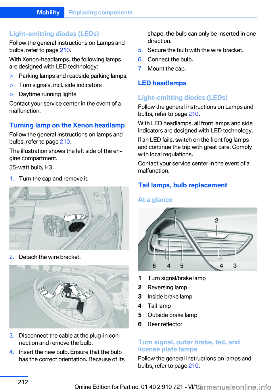
1Turn signal/brake lamp2Reversing lamp3Inside brake lamp4Tail lamp5Outside brake lamp6Rear reflector
Turn signal, outer brake, tail, and
license plate lamps
Follow the general instructions on lamps and
bulbs, refer to page 210.
Seite 212MobilityReplacing components212
Online Edition for Part no. 01 40 2 910 721 - VI/13
Page 235 of 243

Emergency unlocking, trunklid 38
Energy Control 84
Energy recovery 84
Engine, automatic Start/Stop function 65
Engine, automatic switch- off 65
Engine compartment 203
Engine compartment, work‐ ing in 203
Engine coolant 207
Engine idling when driving, coasting 183
Engine oil 205
Engine oil, adding 206
Engine oil additives 206
Engine oil change 206
Engine oil filler neck 206
Engine oil temperature 82
Engine oil types, alterna‐ tive 206
Engine oil types, ap‐ proved 206
Engine start during malfunc‐ tion 31
Engine start, jump-start‐ ing 218
Engine start, refer to Starting the engine 64
Engine stop 64
Engine temperature 82
Entering/exiting vehicle, as‐ sistance, steering wheel 59
Entering a car wash 221
Equipment, interior 164
ESP Electronic Stability Pro‐ gram, refer to DSC 122
Exchanging wheels/tires 199
Exhaust system 174
Exterior mirror, automatic dimming feature 58
Exterior mirrors 57
External start 218
External temperature dis‐ play 83 External temperature warn‐
ing 83
Eyes for securing cargo 178
F
Failure message, refer to Check Control 80
False alarm, refer to Uninten‐ tional alarm 41
Fan, refer to Air flow 158
Fault displays, refer to Check Control 80
Filler neck for engine oil 206
Fine wood, care 224
First aid kit 217
Fitting for towing, refer to Tow fitting 220
Flat tire, changing wheels 213
Flat Tire Monitor FTM 103
Flat tire, Tire Pressure Moni‐ tor TPM 100
Flat tire, warning lamp 101, 104
Flooding 175
Floor carpet, care 224
Floor mats, care 224
Fold-out position, windshield wipers 71
Foot brake 175
Front airbags 96
Front center armrest 170
Front fog lamps 94
Front lamps 210
Front passenger airbags, au‐ tomatic deactivation 98
Front passenger airbags, indi‐ cator lamp 98
Front seats 51
Front turn signals, refer to Light-emitting diodes,
LEDs 212
FTM Flat Tire Monitor 103
Fuel 190
Fuel cap 188 Fuel consumption, current 84
Fuel consumption, refer to Average fuel consump‐
tion 88
Fuel filler flap 188
Fuel gauge 82
Fuel quality 190
Fuel recommendation 190
Fuel, tank capacity 231
Fuse 214
G
Garage door opener, refer to Integrated universal remote
control 164
Gasoline 190
Gasoline quality 190
Gear change, automatic transmission 73
Gear shift indicator 85
General driving notes 174
Glove compartment 169
Gross vehicle weight, ap‐ proved 229
Gross weight, permissible for trailer towing 229
H
Handbrake, refer to Parking brake 67
Hand-held transmitter, alter‐ nating code 165
Hazard warning flashers 216
HDC Hill Descent Con‐ trol 124
Headlamp control, auto‐ matic 92
Headlamp courtesy delay fea‐ ture 91
Headlamp courtesy delay fea‐ ture via remote control 35
Headlamp flasher 70
Headlamp glass 211
Headlamps 210 Seite 235Everything from A to ZReference235
Online Edition for Part no. 01 40 2 910 721 - VI/13
Page 237 of 243

Light-emitting diodes,LEDs 211
Lighting 91
Lighting, speaker 95
Lighting via remote con‐ trol 34
Light switch 91
Load 177
Loading 177
Lock, door 35
Locking/unlocking from in‐ side 36
Locking/unlocking via door lock 35
Locking/unlocking with re‐ mote control 34
Locking, automatic 39
Locking, central 33
Locking, settings 39
Locking via trunk lid 37
Low beams 91
Low beams, automatic, refer to High-beam Assistant 93
Lower back support 52
Lumbar support 52
M
Maintenance 208
Maintenance require‐ ments 208
Maintenance, service require‐ ments 84
Maintenance system, BMW 208
Malfunction displays, refer to Check Control 80
Manual air distribution 158
Manual air flow 158
Manual brake, refer to Parking brake 67
Manual mode, transmis‐ sion 74
Manual operation, backup camera 145 Manual operation, door
lock 36
Manual operation, exterior mirrors 58
Manual operation, fuel filler flap 188
Manual operation, Park Dis‐ tance Control PDC 142
Manual operation, Side View 149
Manual operation, Top View 147
Marking on approved tires 200
Marking, run-flat tires 201
Massage seat, front 53
Master key, refer to Remote control 30
Maximum cooling 159
Maximum speed, display 85
Maximum speed, winter tires 200
Measure, units of 90
Medical kit 217
Memory for seat, mirrors, steering wheel 56
Menu, EfficientDynamics 182
Menu in instrument clus‐ ter 87
Menus, operating, iDrive 16
Menus, refer to iDrive operat‐ ing concept 17
Messages, refer to Check Control 80
Microfilter 160
Minimum tread, tires 199
Mirror 57
Mirror memory 56
Mobile communication devi‐ ces in the vehicle 175
Modifications, technical, refer to Safety 7
Moisture in headlamp 211
Monitor, refer to Control Dis‐ play 16 Mounting of child restraint fix‐
ing systems 60
Multifunctional instrument display 77
Multifunction steering wheel, buttons 12
N
Navigation, see user's manual for Navigation, Entertain‐
ment and Communication
Neck restraints, front, refer to Head restraints 55
Neutral cleaner, see wheel cleaner 224
New wheels and tires 199
Night Vision with pedestrian detection 112
No Passing Information 85
Nylon rope for tow-starting/ towing 220
O OBD Onboard Diagnosis 209
OBD, see OBD Onboard Di‐ agnosis 209
Obstacle marking, rearview camera 146
Octane rating, refer to Gaso‐ line quality 190
Odometer 83
Office, see user's manual for Navigation, Entertainment
and Communication
Oil 205
Oil, adding 206
Oil additives 206
Oil change 206
Oil change interval, service requirements 84
Oil filler neck 206
Oil types, alternative 206
Oil types, approved 206
Old batteries, disposal 214 Seite 237Everything from A to ZReference237
Online Edition for Part no. 01 40 2 910 721 - VI/13
Page 238 of 243
Onboard monitor, refer toControl Display 16
Onboard vehicle tool kit 210
Opening and closing 30
Opening and closing, from in‐ side 36
Opening and closing via door lock 35
Opening and closing, with re‐ mote control 34
Operating concept, iDrive 16
Optional equipment, standard equipment 6
Outside air, refer to Auto‐ matic recirculated-air con‐
trol 159
Overheating of engine, refer to Coolant temperature 83
Overtaking prohibitions 85
P Paint, vehicle 222
Parallel parking assistant 150
Park Distance Control PDC 142
Parked-car heating 161
Parked-car ventilation 161
Parked vehicle, condensa‐ tion 176
Parking aid, refer to PDC 142
Parking assistant 150
Parking brake 67
Parking lamps 91
Parking lamps and roadside parking lamps, refer to
Light-emitting diodes,
LEDs 212
Parking with Auto Hold 68
Passenger side mirror, tilting downward 58
Pathway lines, rearview cam‐ era 145
PDC Park Distance Con‐ trol 142 Pedestrian detection, refer to
Night Vision 112
Pedestrian warning with city braking function 110
People detection, refer to Night Vision 112
Permissible axle load 229
Personal Profile 31
Pinch protection system, win‐ dows 42
Plastic, care 224
Power failure 214
Power windows 41
Pressure, tire air pres‐ sure 191
Pressure warning FTM, tires 103
Profile, refer to Personal Pro‐ file 31
Programmable memory but‐ tons, iDrive 20
Protective function, win‐ dows 42
Push-and-turn switch, refer to Controller 16
Q Queuing Assistant, see Con‐ gestion Assistant 136
R Radiator fluid 207
Radio-operated key, refer to Remote control 30
Radio ready state 64
Radio, see user's manual for Navigation, Entertainment
and Communication
Rain sensor 71
Rear axle steering 125
Rear lamps 212
Rearview mirror 57
Rear window defroster 159
Recirculated-air mode 159 Recommended tire
brands 200
Refueling 188
Remaining range 83
Remote control/key 30
Remote control, malfunc‐ tion 35
Remote control, parked-car heating/ventilation 162
Remote control, univer‐ sal 164
Replacement fuse 214
Replacing bulbs, see Lamp replacement 210
Replacing parts 210
Replacing wheels/tires 199
Reporting safety defects 9
RES button 133
Reserve warning, refer to Range 83
Reset, Tire Pressure Monitor TPM 101
Residual heat, automatic cli‐ mate control 160
Retaining straps, securing cargo 178
Retreaded tires 200
Reversing lamp, bulb replace‐ ment 213
Roadside parking lamps 92
Rollover protection sys‐ tem 99
Roll stabilization, refer to Adaptive Drive 125
Roll stabilization, see Dy‐ namic Drive 125
RON gasoline quality 190
Rope for tow-starting/ towing 220
RSC Run Flat System Com‐ ponent, refer to Run-flat
tires 201
Rubber components, care 224
Run-flat tires 201 Seite 238ReferenceEverything from A to Z238
Online Edition for Part no. 01 40 2 910 721 - VI/13