2014 BMW 640I CONVERTIBLE battery
[x] Cancel search: batteryPage 162 of 243
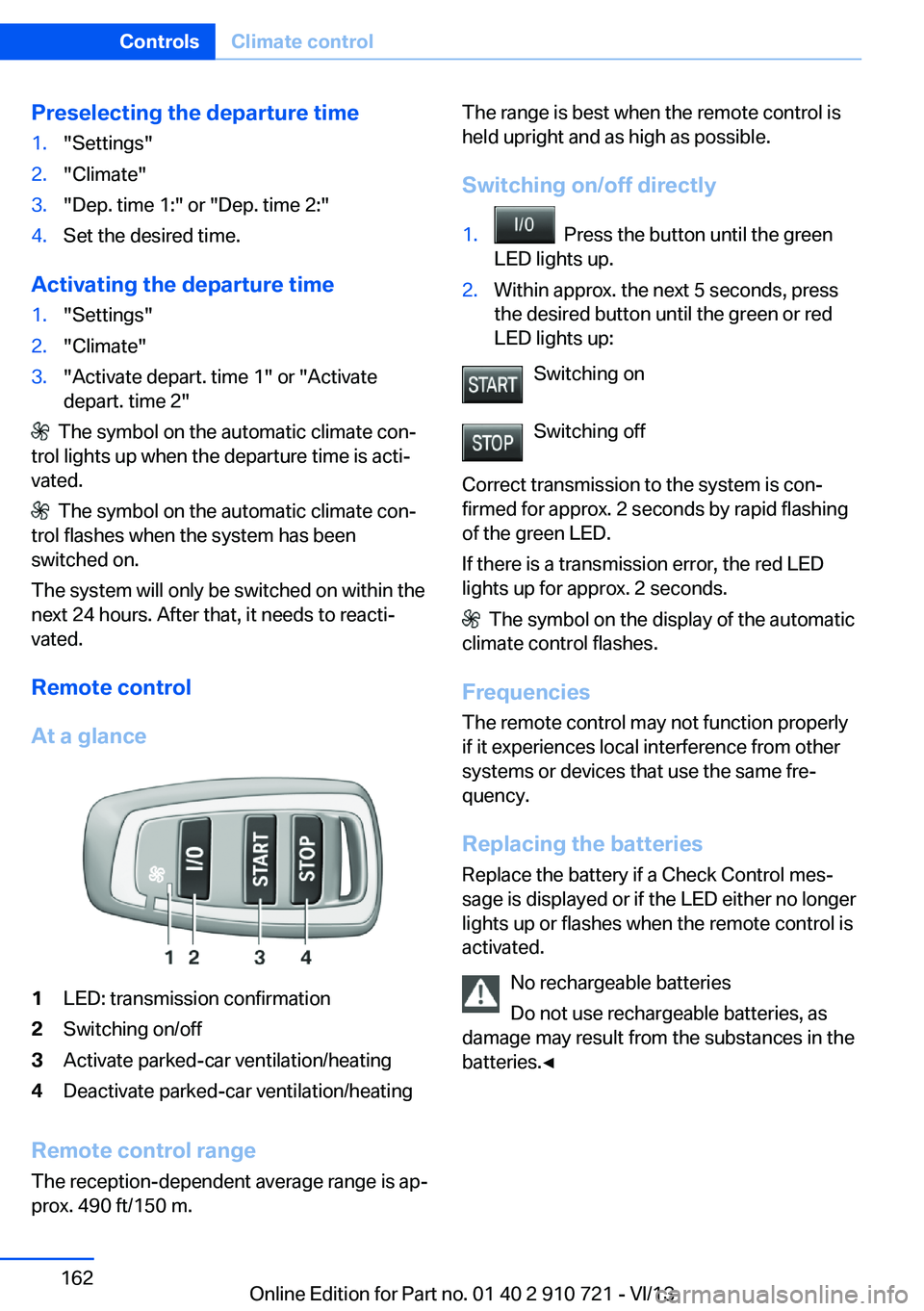
Preselecting the departure time1."Settings"2."Climate"3."Dep. time 1:" or "Dep. time 2:"4.Set the desired time.
Activating the departure time
1."Settings"2."Climate"3."Activate depart. time 1" or "Activate
depart. time 2"
The symbol on the automatic climate con‐
trol lights up when the departure time is acti‐
vated.
The symbol on the automatic climate con‐
trol flashes when the system has been
switched on.
The system will only be switched on within the
next 24 hours. After that, it needs to reacti‐
vated.
Remote control
At a glance
1LED: transmission confirmation2Switching on/off3Activate parked-car ventilation/heating4Deactivate parked-car ventilation/heating
Remote control range The reception-dependent average range is ap‐
prox. 490 ft/150 m.
The range is best when the remote control is
held upright and as high as possible.
Switching on/off directly1. Press the button until the green
LED lights up.2.Within approx. the next 5 seconds, press
the desired button until the green or red
LED lights up:
Switching on
Switching off
Correct transmission to the system is con‐
firmed for approx. 2 seconds by rapid flashing
of the green LED.
If there is a transmission error, the red LED
lights up for approx. 2 seconds.
The symbol on the display of the automatic
climate control flashes.
Frequencies The remote control may not function properly
if it experiences local interference from other
systems or devices that use the same fre‐
quency.
Replacing the batteries Replace the battery if a Check Control mes‐
sage is displayed or if the LED either no longer
lights up or flashes when the remote control is
activated.
No rechargeable batteries
Do not use rechargeable batteries, as
damage may result from the substances in the
batteries.◀
Seite 162ControlsClimate control162
Online Edition for Part no. 01 40 2 910 721 - VI/13
Page 163 of 243
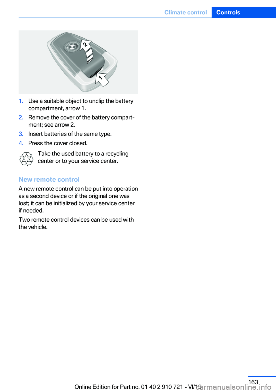
1.Use a suitable object to unclip the battery
compartment, arrow 1.2.Remove the cover of the battery compart‐
ment; see arrow 2.3.Insert batteries of the same type.4.Press the cover closed.
Take the used battery to a recycling
center or to your service center.
New remote control A new remote control can be put into operation
as a second device or if the original one was
lost; it can be initialized by your service center
if needed.
Two remote control devices can be used with
the vehicle.
Seite 163Climate controlControls163
Online Edition for Part no. 01 40 2 910 721 - VI/13
Page 167 of 243
Connecting electrical
devices
Hints Do not plug chargers into the socket
Do not connect battery chargers to the
factory-installed sockets in the vehicle as this
may damage the battery.◀
Replace the cover after use
Reinsert the lighter or socket cover after
use, otherwise objects may get into the lighter
socket or fixture and cause a short circuit.◀
Sockets
The lighter socket can be used as a socket for
electrical equipment while the engine is run‐
ning or when the ignition is switched on. The
total load of all sockets must not exceed
140 watts at 12 volts.
Do not damage the socket by using unsuitable
connectors.
Automatic transmission: center
console
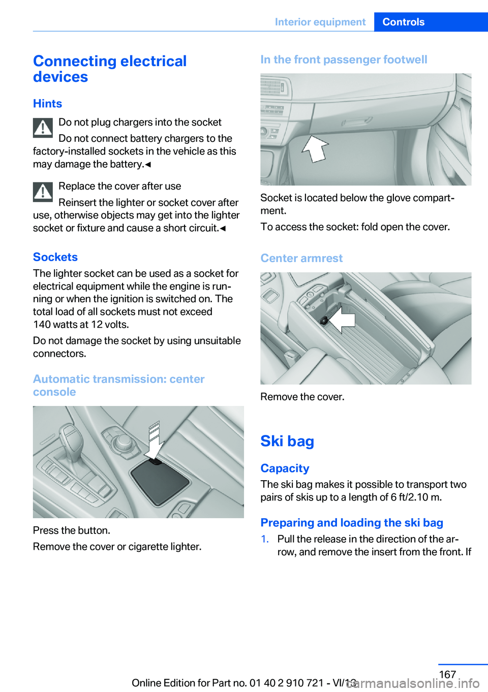
Press the button.
Remove the cover or cigarette lighter.
In the front passenger footwell
Socket is located below the glove compart‐
ment.
To access the socket: fold open the cover.
Center armrest
Remove the cover.
Ski bag
Capacity The ski bag makes it possible to transport two
pairs of skis up to a length of 6 ft/2.10 m.
Preparing and loading the ski bag
1.Pull the release in the direction of the ar‐
row, and remove the insert from the front. IfSeite 167Interior equipmentControls167
Online Edition for Part no. 01 40 2 910 721 - VI/13
Page 183 of 243
Coasting
The concept The system helps to conserve fuel.
To do this, under certain conditions the engine
is automatically decoupled from the transmis‐
sion when transmission position D is engaged.
The vehicle continues traveling with the engine
idling to reduce fuel consumption. Transmis‐
sion position D remains engaged.
This driving condition is referred to as coast‐
ing.
As soon as the brake or accelerator pedal is depressed, the engine is automatically coupled
to the transmission again.
Hints
Coasting is a component of the ECO PRO, re‐
fer to page 180, driving mode.
The function is available in a certain speed
range.
A forward-looking driving style helps the driver
to use the function as often as possible and
supports the fuel-conserving effect of coast‐
ing.
Safety mode
The function is not available if one of the fol‐
lowing conditions is satisfied.▷DSC OFF or TRACTION activated.▷Driving in the dynamic limit range and on
steep uphill or downhill grades.▷Battery charge status temporarily too low
or vehicle electrical system drawing exces‐
sive current.▷Cruise control activated.
Functional requirements
In ECO PRO mode, this function is available in
a speed range from approximately 30 mph, ap‐
prox. 50 km/h to 100 mph, approx. 160 km/h, if
the following conditions are satisfied:
▷Accelerator pedal and brake pedal are not
operated.▷The selector lever is in transmission posi‐
tion D.▷Engine and transmission are at operating
temperature.
Display
Display in the instrument cluster The mark in the bar display be‐
low the tachometer is backlit in
blue and is located at the zero
point. The tachometer approxi‐
mately indicates idle speed.
The coasting point indicator is illuminated at
the zero point during coasting.
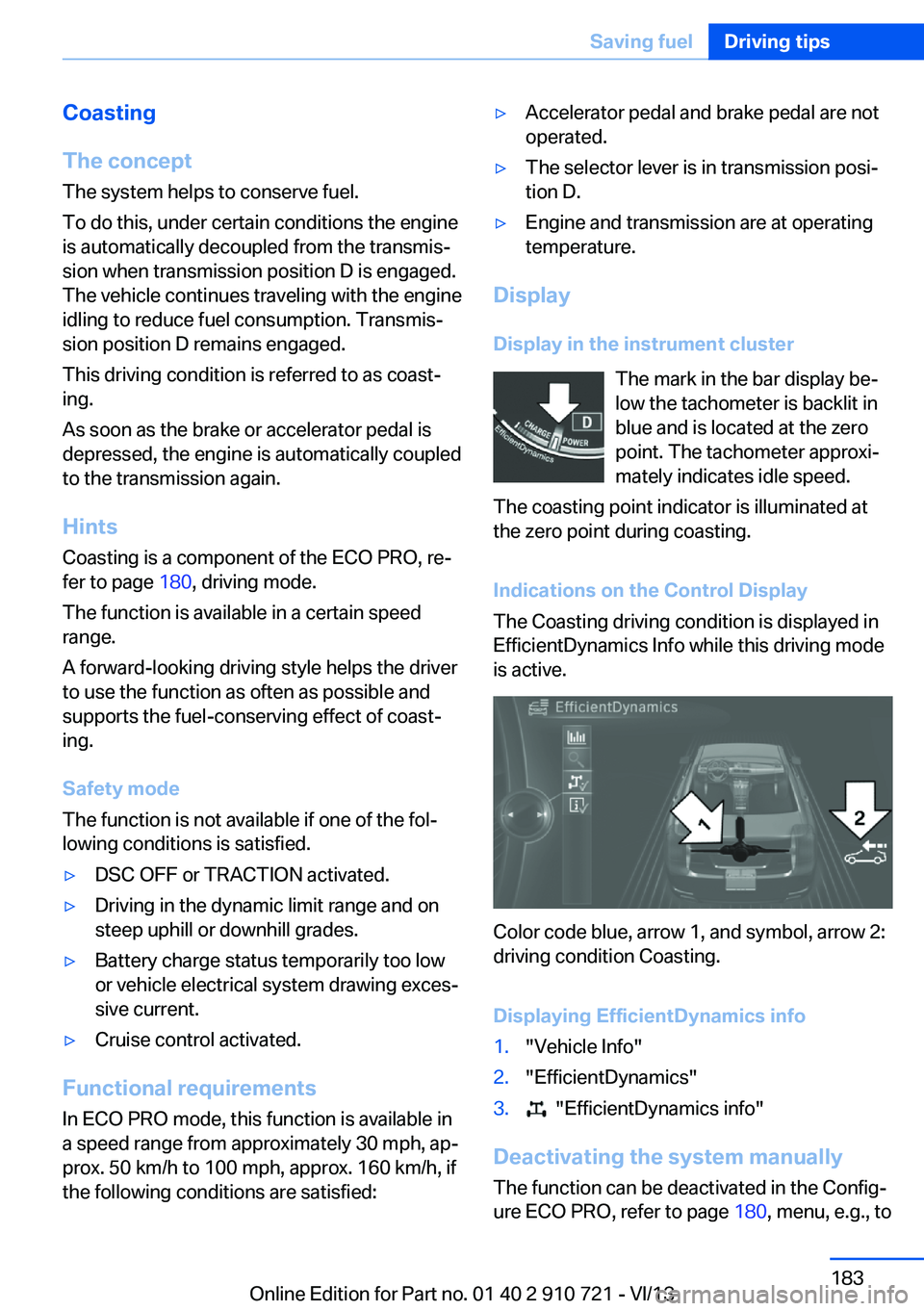
Indications on the Control Display
The Coasting driving condition is displayed in
EfficientDynamics Info while this driving mode
is active.
Color code blue, arrow 1, and symbol, arrow 2:
driving condition Coasting.
Displaying EfficientDynamics info
1."Vehicle Info"2."EfficientDynamics"3. "EfficientDynamics info"
Deactivating the system manually The function can be deactivated in the Config‐
ure ECO PRO, refer to page 180, menu, e.g., to
Seite 183Saving fuelDriving tips183
Online Edition for Part no. 01 40 2 910 721 - VI/13
Page 214 of 243
Vehicle batteryMaintenance
The battery is maintenance-free, i.e., the elec‐ trolyte will last for the life of the battery.
Your service center will be glad to advise you
on questions regarding the battery.
Battery replacement Use approved vehicle batteries only
Only use vehicle batteries that have been
approved for your vehicle by the manufacturer; otherwise, the vehicle could be damaged and
systems or functions may not be fully availa‐
ble.◀
After a battery replacement, have the battery registered on the vehicle by your service cen‐
ter to ensure that all comfort functions are fully
available and that any Check Control mes‐
sages of these comfort functions are no longer
displayed.
Charging the battery
Note Do not plug chargers into the socket
Do not connect battery chargers to the
factory-installed sockets in the vehicle as this
may damage the battery.◀
General information
Make sure that the battery is always suffi‐
ciently charged to guarantee that the battery
remains usable for its full service life.
The battery may need to be charged in the fol‐
lowing cases:▷When making frequent short-distance
drives.▷If the vehicle is not used for prolonged pe‐
riods, longer than a month.Starting aid terminals
In the vehicle, only charge the battery via the
starting aid terminals, refer to page 218, in the
engine compartment with the engine off.
Power failure After a temporary power loss, some equipment
needs to be reinitialized.
Individual settings need to be reprogrammed:▷Seat, mirror, and steering wheel memory:
store the positions again.▷Time: update.▷Date: update.▷Radio station: saving new, see user's
manual for Navigation, Entertainment and
Communication.▷Navigation system: wait for the operability
of the navigation.
Disposing of old batteries
Have old batteries disposed of by your
service center or bring them to a recy‐
cling center.
Maintain the battery in an upright position for
transport and storage. Secure the battery so
that it does not tip over during transport.
Fuses Notes Replacing fuses
Never attempt to repair a blown fuse and
do not replace a defective fuse with a substi‐
tute of another color or amperage rating; this could lead to a circuit overload, ultimately re‐
sulting in a fire in the vehicle.◀
Plastic tweezers and information on the fuse
types and locations are stored in the fuse box
in the cargo area.
Seite 214MobilityReplacing components214
Online Edition for Part no. 01 40 2 910 721 - VI/13
Page 218 of 243
Roadside Assistance can be established di‐
rectly.
Jump-starting
Notes If the battery is discharged, an engine can be
started using the battery of another vehicle
and two jumper cables. Only use jumper ca‐
bles with fully insulated clamp handles.
To prevent personal injury or damage to both
vehicles, adhere strictly to the following proce‐
dure.
Do not touch live parts
To avoid the risk of potentially fatal in‐
jury, always avoid all contact with electrical
components while the engine is running.◀
Preparation1.Check whether the battery of the other ve‐
hicle has a voltage of 12 volts. This infor‐
mation can be found on the battery.2.Switch off the engine of the assisting vehi‐
cle.3.Switch off any electronic systems/power
consumers in both vehicles.
Bodywork contact between vehicles
Make sure that there is no contact be‐
tween the bodywork of the two vehicles; other‐
wise, there is the danger of short circuits.◀
Starting aid terminals Connecting order
Connect the jumper cables in the correct
order; otherwise, there is the danger of injury
from sparking.◀
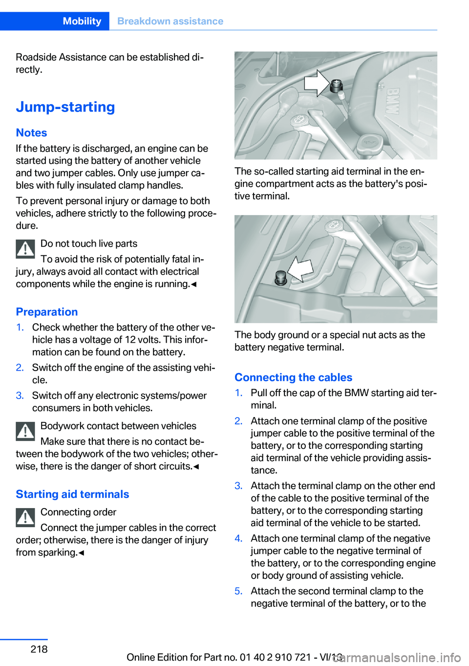
The so-called starting aid terminal in the en‐
gine compartment acts as the battery's posi‐
tive terminal.
The body ground or a special nut acts as the
battery negative terminal.
Connecting the cables
1.Pull off the cap of the BMW starting aid ter‐
minal.2.Attach one terminal clamp of the positive
jumper cable to the positive terminal of the
battery, or to the corresponding starting
aid terminal of the vehicle providing assis‐
tance.3.Attach the terminal clamp on the other end
of the cable to the positive terminal of the
battery, or to the corresponding starting
aid terminal of the vehicle to be started.4.Attach one terminal clamp of the negative
jumper cable to the negative terminal of
the battery, or to the corresponding engine
or body ground of assisting vehicle.5.Attach the second terminal clamp to the
negative terminal of the battery, or to theSeite 218MobilityBreakdown assistance218
Online Edition for Part no. 01 40 2 910 721 - VI/13
Page 219 of 243
corresponding engine or body ground of
the vehicle to be started.
Starting the engine
Never use spray fluids to start the engine.
1.Start the engine of the assisting vehicle
and let it run for several minutes at an in‐
creased idle speed.2.Start the engine of the vehicle being
started in the usual way.
If the first starting attempt is not success‐
ful, wait a few minutes before making an‐
other attempt in order to allow the dis‐
charged battery to recharge.3.Let both engines run for several minutes.4.Disconnect the jumper cables in the re‐
verse order.
Check the battery and recharge if necessary.
Tow-starting and towing Automatic transmission: transporting
your vehicle
Note
Your vehicle is not permitted to be towed.
Therefore, contact a service center in the
event of a breakdown.
Do not have the vehicle towed
Have your vehicle transported on a load‐
ing platform only; otherwise, damage may oc‐
cur.◀
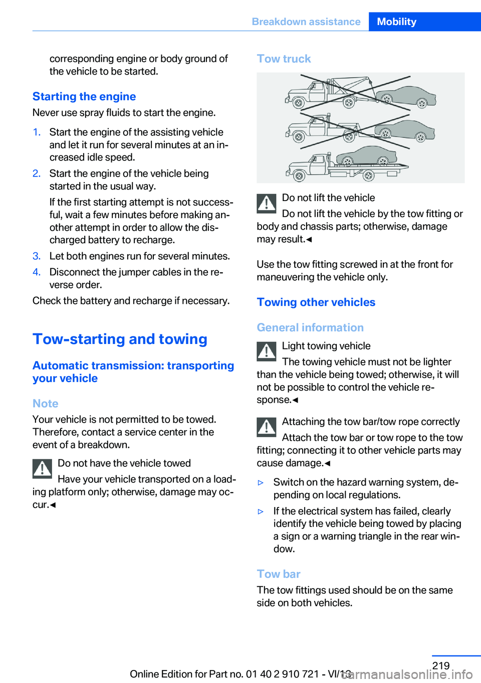
Tow truck
Do not lift the vehicle
Do not lift the vehicle by the tow fitting or
body and chassis parts; otherwise, damage
may result.◀
Use the tow fitting screwed in at the front for
maneuvering the vehicle only.
Towing other vehicles
General information Light towing vehicle
The towing vehicle must not be lighter
than the vehicle being towed; otherwise, it will
not be possible to control the vehicle re‐
sponse.◀
Attaching the tow bar/tow rope correctly
Attach the tow bar or tow rope to the tow
fitting; connecting it to other vehicle parts may
cause damage.◀
▷Switch on the hazard warning system, de‐
pending on local regulations.▷If the electrical system has failed, clearly
identify the vehicle being towed by placing
a sign or a warning triangle in the rear win‐
dow.
Tow bar
The tow fittings used should be on the same
side on both vehicles.
Seite 219Breakdown assistanceMobility219
Online Edition for Part no. 01 40 2 910 721 - VI/13
Page 232 of 243
Everything from A to Z
IndexA ABS, Antilock Brake Sys‐ tem 122
ACC, Active Cruise Control with Stop & Go 130
Activated-charcoal filter 160
Active Blind Spot Detec‐ tion 117
Active Cruise Control with Stop & Go, ACC 130
Active Protection 119
Active roll stabilization, see Dynamic Drive 125
Active seat, front 53
Active seat ventilation, front 53
Active Steering, integral 125
Adaptive brake assistant 122
Adaptive brake lights, refer to Brake force display 119
Adaptive drive 125
Adaptive light control 92
Additives, oil 206
Adjusting, steering wheel 59
Adjustments, seats/head re‐ straints 51
After washing vehicle 222
Airbags 96
Airbags, indicator/warning light 97
Air circulation, refer to Recir‐ culated-air mode 159
Air distribution, manual 158
Air drying, refer to Cooling function 159
Air flow, automatic climate control 158
Air pressure, tires 191
Air vents, refer to Ventila‐ tion 160 Alarm system 40
Alarm, unintentional 41
All around the center con‐ sole 14
All around the interior rear‐ view mirror 15
All around the steering wheel 12
All-season tires, refer to Win‐ ter tires 200
All-wheel-drive 124
Alternating-code hand-held transmitter 165
Alternative oil types 206
Ambient light 94
Antifreeze, washer fluid 72
Antilock Brake System, ABS 122
Anti-slip control, refer to DSC 122
Approved engine oils 206
Armrest, refer to Front center armrest 170
Arrival time 88
Ashtray 166
Assistance, Roadside Assis‐ tance 217
Assistance when driving off 122
Attentiveness assistant 119
AUTO H button, refer to Au‐ tomatic Hold 68
AUTO intensity 158
Automatic car wash 221
Automatic Cruise Control with Stop & Go 130
Automatic Curb Monitor 58
Automatic deactivation, front passenger airbags 98
Automatic headlamp con‐ trol 92 Automatic Hold 68
Automatic locking 39
Automatic recirculated-air control 159
Automatic Soft Closing, doors 36
Automatic transmission with Steptronic 72
AUTO program, automatic cli‐ mate control 158
AUTO program, intensity 158
Auto Start/Stop function 65
Average fuel consumption 88
Average speed 88
Axle loads, weights 229
B Backrest curvature, refer to Lumbar support 52
Backrest, seats 51
Backrest, width 52
Backup camera 144
Band-aids, refer to First aid kit 217
Bar for tow-starting/ towing 219
Battery replacement, remote control for parked-car heat‐
ing/ventilation 162
Battery replacement, vehicle battery 214
Battery replacement, vehicle remote control 30
Battery, vehicle 214
Belts, safety belts 54
Beverage holder, cu‐ pholder 171
BMW Assist, see user's manual for Navigation, En‐Seite 232ReferenceEverything from A to Z232
Online Edition for Part no. 01 40 2 910 721 - VI/13