2014 BMW 640I CONVERTIBLE warning
[x] Cancel search: warningPage 78 of 243
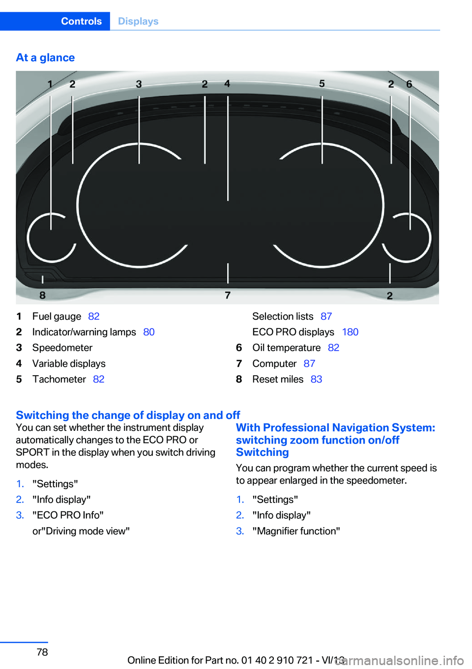
At a glance1Fuel gauge 822Indicator/warning lamps 803Speedometer4Variable displays5Tachometer 82Selection lists 87
ECO PRO displays 1806Oil temperature 827Computer 878Reset miles 83
Switching the change of display on and off
You can set whether the instrument display
automatically changes to the ECO PRO or
SPORT in the display when you switch driving
modes.1."Settings"2."Info display"3."ECO PRO Info"
or"Driving mode view"With Professional Navigation System:
switching zoom function on/off
Switching
You can program whether the current speed is
to appear enlarged in the speedometer.1."Settings"2."Info display"3."Magnifier function"Seite 78ControlsDisplays78
Online Edition for Part no. 01 40 2 910 721 - VI/13
Page 80 of 243
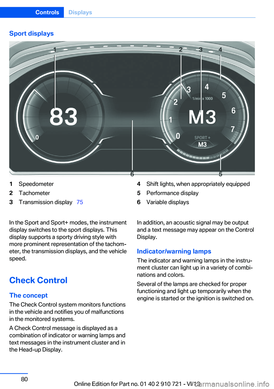
Sport displays1Speedometer2Tachometer3Transmission display 754Shift lights, when appropriately equipped5Performance display6Variable displaysIn the Sport and Sport+ modes, the instrument
display switches to the sport displays. This
display supports a sporty driving style with
more prominent representation of the tachom‐
eter, the transmission displays, and the vehicle
speed.
Check Control
The concept The Check Control system monitors functions
in the vehicle and notifies you of malfunctions
in the monitored systems.
A Check Control message is displayed as a
combination of indicator or warning lamps and
text messages in the instrument cluster and in
the Head-up Display.In addition, an acoustic signal may be output and a text message may appear on the Control
Display.
Indicator/warning lamps
The indicator and warning lamps in the instru‐
ment cluster can light up in a variety of combi‐
nations and colors.
Several of the lamps are checked for proper
functioning and light up temporarily when the
engine is started or the ignition is switched on.Seite 80ControlsDisplays80
Online Edition for Part no. 01 40 2 910 721 - VI/13
Page 81 of 243

Overview: indicator/warning lampsSymbolFunction or systemTurn signal.Parking brake.Parking brake in Canadian models.Automatic hold.Front fog lamps.High beams.High-beam Assistant.Parking lamps, headlamp control.Active Cruise Control.Vehicle detection, Active Cruise
Control: collision warning.Cruise control.Lane departure warning.DSC Dynamic Stability Control.DSC Dynamic Stability Control or
DTC Dynamic Traction ControlSymbolFunction or systemTire Pressure Monitor.
Flat Tire Monitor.Safety belts.Airbag system.Steering system.Engine functions.Engine functions in Canadian mod‐
els.Brake system.Brake system in Canadian models.ABS Antilock Brake System.ABS Antilock Brake System in
Canadian models.At least one Check Control mes‐
sage is displayed or is stored.
Text messages
Text messages in combination with a symbol
in the instrument cluster explain a Check Con‐ trol message and the meaning of the indicator
and warning lamps.
Supplementary text messages
Additional information, such as on the cause of
a fault or the required action, can be called up
via Check Control.
Seite 81DisplaysControls81
Online Edition for Part no. 01 40 2 910 721 - VI/13
Page 82 of 243
The supplementary text of urgent messages is
automatically displayed on the Control Display.
Symbols
Depending on the Check Control message, the
following functions can be selected.▷ "Owner's Manual"
Display additional information about the
Check Control message in the Integrated
Owner's Manual.▷ "Service request"
Contact the service partner.▷ "Roadside Assistance"
Contact Roadside Assistance.
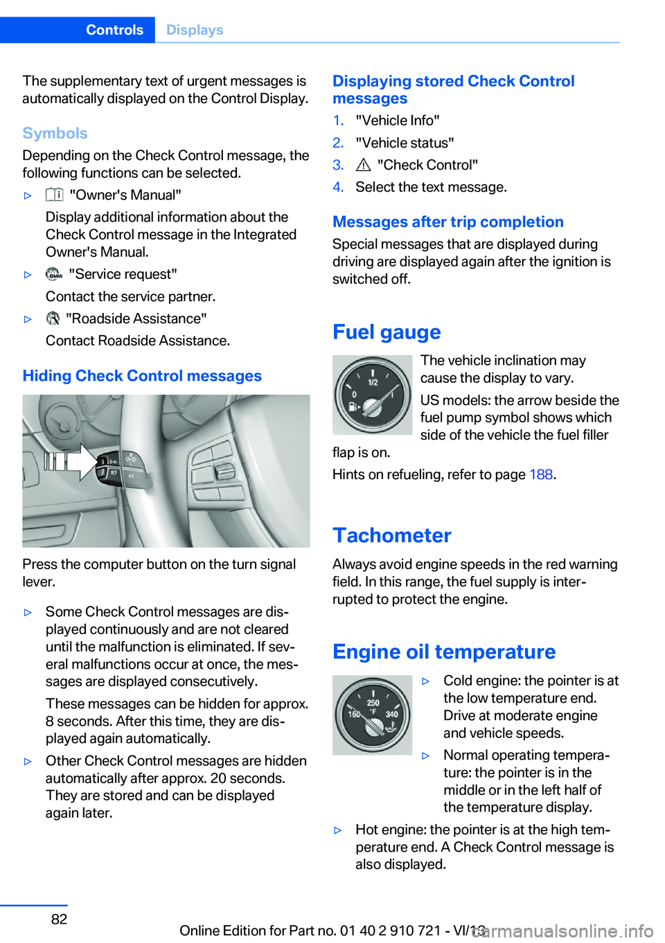
Hiding Check Control messages
Press the computer button on the turn signal
lever.
▷Some Check Control messages are dis‐
played continuously and are not cleared
until the malfunction is eliminated. If sev‐
eral malfunctions occur at once, the mes‐
sages are displayed consecutively.
These messages can be hidden for approx.
8 seconds. After this time, they are dis‐
played again automatically.▷Other Check Control messages are hidden
automatically after approx. 20 seconds.
They are stored and can be displayed
again later.Displaying stored Check Control
messages1."Vehicle Info"2."Vehicle status"3. "Check Control"4.Select the text message.
Messages after trip completion
Special messages that are displayed during
driving are displayed again after the ignition is
switched off.
Fuel gauge The vehicle inclination may
cause the display to vary.
US models: the arrow beside the
fuel pump symbol shows which
side of the vehicle the fuel filler
flap is on.
Hints on refueling, refer to page 188.
Tachometer
Always avoid engine speeds in the red warning
field. In this range, the fuel supply is inter‐
rupted to protect the engine.
Engine oil temperature
▷Cold engine: the pointer is at
the low temperature end.
Drive at moderate engine
and vehicle speeds.▷Normal operating tempera‐
ture: the pointer is in the
middle or in the left half of
the temperature display.▷Hot engine: the pointer is at the high tem‐
perature end. A Check Control message is
also displayed.Seite 82ControlsDisplays82
Online Edition for Part no. 01 40 2 910 721 - VI/13
Page 83 of 243
Coolant temperatureIf the coolant along with the engine becomes
too hot, a Check Control message is displayed.
Check the coolant level, refer to page 207.
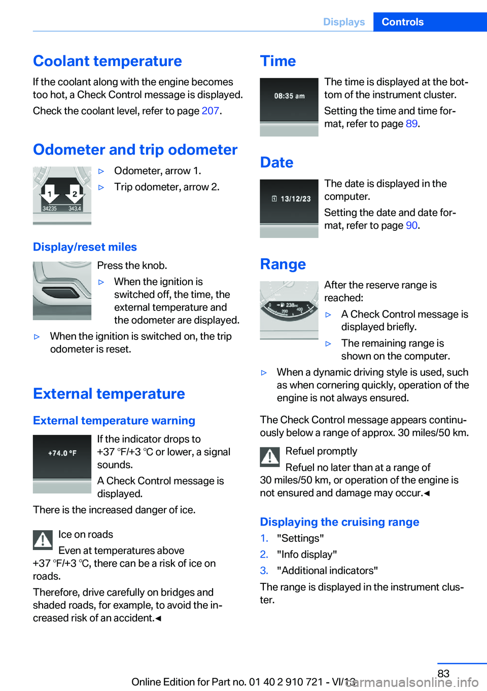
Odometer and trip odometer▷Odometer, arrow 1.▷Trip odometer, arrow 2.
Display/reset miles Press the knob.
▷When the ignition is
switched off, the time, the
external temperature and
the odometer are displayed.▷When the ignition is switched on, the trip
odometer is reset.
External temperature
External temperature warning If the indicator drops to
+37 ℉/+3 ℃ or lower, a signal
sounds.
A Check Control message is displayed.
There is the increased danger of ice.
Ice on roads
Even at temperatures above
+37 ℉/+3 ℃, there can be a risk of ice on
roads.
Therefore, drive carefully on bridges and
shaded roads, for example, to avoid the in‐
creased risk of an accident.◀
Time
The time is displayed at the bot‐
tom of the instrument cluster.
Setting the time and time for‐
mat, refer to page 89.
Date The date is displayed in the
computer.
Setting the date and date for‐
mat, refer to page 90.
Range After the reserve range isreached:▷A Check Control message is
displayed briefly.▷The remaining range is
shown on the computer.▷When a dynamic driving style is used, such
as when cornering quickly, operation of the
engine is not always ensured.
The Check Control message appears continu‐
ously below a range of approx. 30 miles/50 km.
Refuel promptly
Refuel no later than at a range of
30 miles/50 km, or operation of the engine is
not ensured and damage may occur.◀
Displaying the cruising range
1."Settings"2."Info display"3."Additional indicators"
The range is displayed in the instrument clus‐
ter.
Seite 83DisplaysControls83
Online Edition for Part no. 01 40 2 910 721 - VI/13
Page 88 of 243
Information at a glanceRepeatedly pressing the button on the turn
signal lever calls up the following information
on the info display:▷Range.▷Average fuel consumption.▷Average speed.▷Date.▷Speed limit detection.▷Time of arrival.
When destination guidance is activated in
the navigation system.▷Distance to destination.
When destination guidance is activated in
the navigation system.▷Arrow view of navigation system.
When destination guidance is activated in
the navigation system.
When the arrow view in the Head-up Dis‐
play is inactive.▷ECO PRO bonus range.
Adjusting the info display
You can select what information from the on‐
board computer is to be displayed on the info
display of the instrument cluster.
1."Settings"2."Info display"3.Select the desired displays.
Information in detail
Range
Displays the estimated cruising range available
with the remaining fuel.
It is calculated based on your driving style over
the last 20 miles/30 km. If there is only enough
fuel left for less than 45 miles/80 km, the color
of the display changes.
Average fuel consumption
The average fuel consumption is calculated for
the period during which the engine is running.
The average fuel consumption is calculated for
the distance traveled since the last reset by the
onboard computer.
Average speed
Periods in which the vehicle is parked with the
engine manually stopped do not enter into the
calculation of the average speed.
Resetting average values
Press and hold the computer button on the
turn signal lever.
Distance to destination
The distance remaining to the destination is
displayed if a destination is entered in the navi‐
gation system before the trip is started.
The distance to the destination is adopted au‐
tomatically.
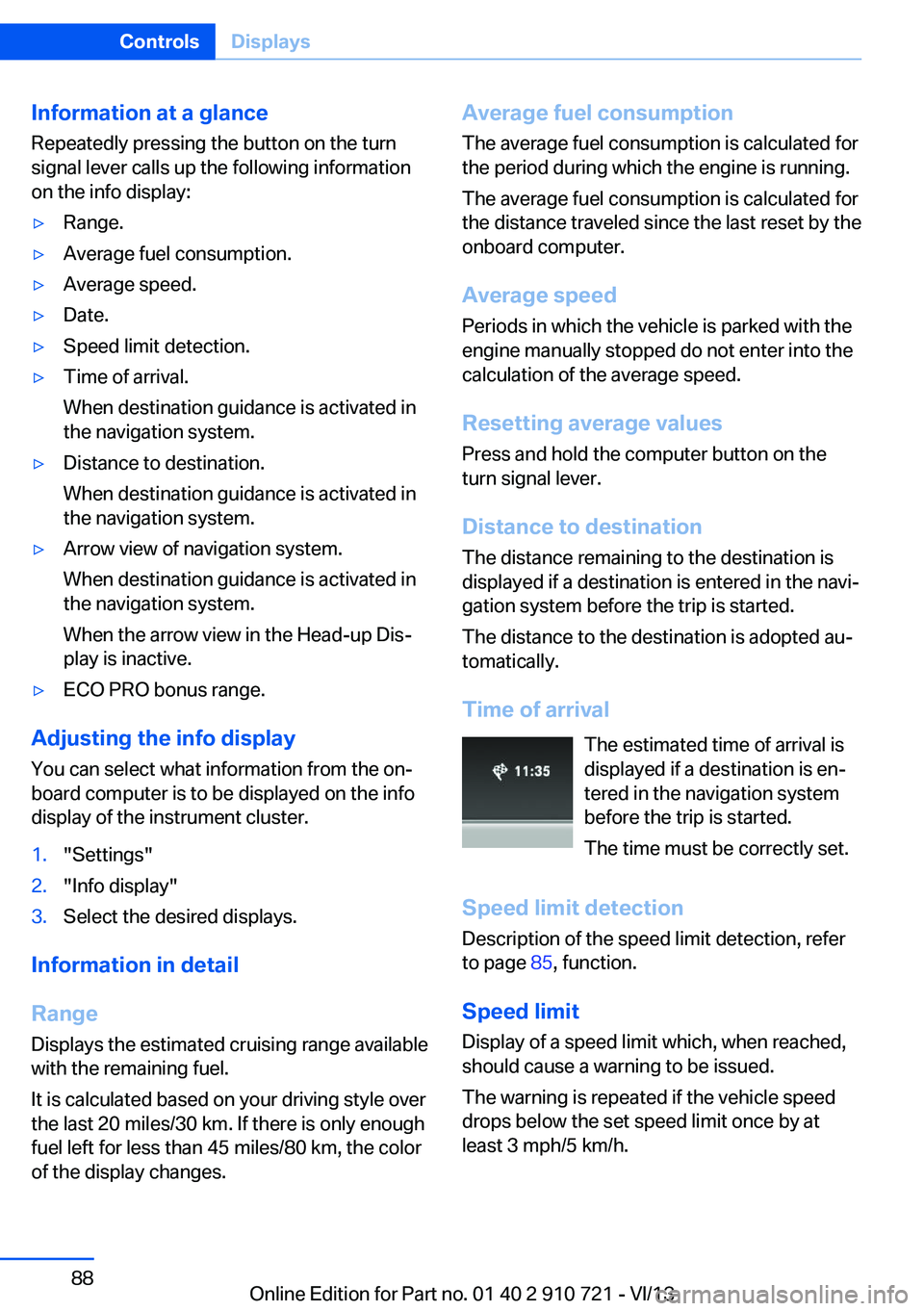
Time of arrival The estimated time of arrival is
displayed if a destination is en‐
tered in the navigation system
before the trip is started.
The time must be correctly set.
Speed limit detection
Description of the speed limit detection, refer
to page 85, function.
Speed limit Display of a speed limit which, when reached,
should cause a warning to be issued.
The warning is repeated if the vehicle speed
drops below the set speed limit once by at
least 3 mph/5 km/h.Seite 88ControlsDisplays88
Online Edition for Part no. 01 40 2 910 721 - VI/13
Page 89 of 243
Displaying, setting or changing the
limit1."Settings"2."Speed"3."Warning at:"4.Turn the controller until the desired limit is
displayed.5.Press the controller.
The speed limit is stored.
Activating/deactivating the limit
1."Settings"2."Speed"3."Warning"4.Press the controller.
Setting your current speed as the limit
1."Settings"2."Speed"3."Select current speed"4.Press the controller.
The current vehicle speed is stored as the
limit.
Trip computer
The vehicle features two types of computer.
▷"Onboard info": the values can be reset as
often as necessary.▷"Trip computer": the values provide an
overview of the current trip.
Resetting the trip computer
1."Vehicle Info"2."Trip computer"3."Reset": all values are reset.
"Automatically reset": all values are reset
approx. 4 hours after the vehicle comes to
a standstill.Display on the Control Display
Display the onboard computer or trip computer
on the Control Display.1."Vehicle Info"2."Onboard info" or "Trip computer"
Resetting the fuel consumption or
speed
1."Vehicle Info"2."Onboard info"3."Consumpt." or "Speed"4."Yes"
Settings on the Control
Display
Time
Setting the time zone
1."Settings"2."Time/Date"3."Time zone"4.Select the desired time zone.
The time zone is stored.
Setting the time
1."Settings"2."Time/Date"3."Time:"4.Turn the controller until the desired hours
are displayed.5.Press the controller.6.Turn the controller until the desired mi‐
nutes are displayed.7.Press the controller.
The time is stored.
Seite 89DisplaysControls89
Online Edition for Part no. 01 40 2 910 721 - VI/13
Page 97 of 243
▷Keep at a distance from the airbags.▷Always grasp the steering wheel on the
steering wheel rim, holding your hands at
the 3 o'clock and 9 o'clock positions, to
keep the danger of injury to your hands or
arms as low as possible if the airbag is trig‐
gered.▷There should be no people, animals, or ob‐
jects between an airbag and a person.▷Do not use the cover of the front airbag on
the front passenger side as a storage area.▷Keep the dashboard and window on the
front passenger side clear, i.e., do not
cover with adhesive labels or coverings,
and do not attach holders such as for navi‐
gation instruments and mobile phones.▷Make sure that the front passenger is sit‐
ting correctly, i.e., keeps his or her feet and
legs in the footwell; otherwise, leg injuries
can occur if the front airbag is triggered.▷Do not place slip covers, seat cushions or
other objects on the front passenger seat
that are not approved specifically for seats
with integrated side airbags.▷Do not hang pieces of clothing, such as
jackets, over the backrests.▷Make sure that occupants keep their heads
away from the side airbag; otherwise, inju‐
ries can occur if the airbags are deployed.▷Do not remove the airbag restraint system.▷Do not remove the steering wheel.▷Do not apply adhesive materials to the air‐
bag cover panels, cover them or modify
them in any way.▷Never modify either the individual compo‐
nents or the wiring in the airbag system.
This also applies to steering wheel covers,
the dashboard, and the seats.◀
Even when all instructions are followed closely,
injury from contact with the airbags cannot be
ruled out in certain situations.
The ignition and inflation noise may lead to
short-term and, in most cases, temporary
hearing impairment in sensitive individuals.
In the case of a malfunction, deactivation
and after triggering of the airbags
Do not touch the individual components imme‐
diately after the system has been triggered;
otherwise, there is the danger of burns.
Only have the airbags checked, repaired or dis‐
mantled and the airbag generator scrapped by
your service center or a workshop that has the
necessary authorization for handling explo‐
sives.
Non-professional attempts to service the sys‐
tem could lead to failure in an emergency or
undesired triggering of the airbag, either of
which could result in injury.◀
Warnings and information on the airbags are
also found on the sun visors.
Functional readiness of the airbag
system
When the ignition is switch on, the
warning lamp in the instrument cluster
lights up briefly and thereby indicates
the operational readiness of the entire airbag
system and the belt tensioner.
Airbag system malfunctioning▷Warning lamp does not come on when the
ignition is turned on.▷The warning lamp lights up continuously.
When there is a malfunction, have the
airbag system checked immediately
When there is a malfunction, have the airbag
system checked immediately; otherwise, there
is a risk that the system does not function as
expected in the event of an accident despite
corresponding severity of the accident.◀
Seite 97SafetyControls97
Online Edition for Part no. 01 40 2 910 721 - VI/13