2014 BMW 6 SERIES COUPE change time
[x] Cancel search: change timePage 111 of 247

FTM Flat Tire MonitorThe concept
The system detects tire inflation pressure loss
on the basis of rotation speed differences be‐
tween the individual wheels while driving.
In the event of a tire inflation pressure loss, the
diameter and therefore the rotational speed of
the corresponding wheel changes. This will be
detected and reported as a flat tire.
The system does not measure the actual infla‐
tion pressure in the tires.
Functional requirements
The system must have been initialized when
the tire inflation pressure was correct; other‐
wise, reliable flagging of a flat tire is not as‐
sured. Initialize the system after each correc‐
tion of the tire inflation pressure and after
every tire or wheel change.
Status display The current status of the Flat Tire Monitor canbe displayed on the Control Display, e.g.,
whether or not the FTM is active.
On the Control Display:1."Vehicle info"2."Vehicle status"3. "Flat Tire Monitor (FTM)"
The status is displayed.
Initialization
When initializing the once set inflation tire
pressures serve as reference values in order to
detect a flat tire. Initialization is started by con‐
firming the tire inflation pressures.
Do not initialize the system when driving with
snow chains.
On the Control Display:
1."Vehicle info"2."Vehicle status"3. "Perform reset"4.Start the engine - do not drive off.5.Start the initialization with "Perform reset".6.Drive away.
The initialization is completed while driving,
which can be interrupted at any time.
The initialization automatically continues when
driving resumes.
Indication of a flat tire The yellow warning lamp lights up. A
Check Control message is displayed.
There is a flat tire or a major loss in tire
inflation pressure.
1.Reduce your speed and stop cautiously.
Avoid sudden braking and steering maneu‐
vers.2.Check whether the vehicle is fitted with
regular tires or run-flat tires.
Run-flat tires, refer to page 200, are la‐
beled with a circular symbol containing the
letters RSC marked on the tire's sidewall.
Do not continue driving without run-flat
tires
Do not continue driving if the vehicle is not
equipped with run-flat tires; continued driving
may result in serious accidents.◀
When a flat tire is indicated, DSC Dynamic Sta‐
bility Control is switched on if needed.
System limits Sudden tire damage
Sudden serious tire damage caused by
external circumstances cannot be recognized
in advance.◀
A natural, even tire inflation pressure loss in all
four tires will not be recognized. Therefore,
check the tire inflation pressure regularly.
The system could be delayed or malfunction in
the following situations:
Seite 107SafetyControls107
Online Edition for Part no. 01 40 2 956 387 - X/14
Page 126 of 247

▷Arrows: at least one lane marking was de‐
tected and warnings can be issued.
Display in the instrument display
▷Symbol orange: system is acti‐
vated.▷Symbol green: at least one lane
marking was detected and warn‐
ings can be issued.
Issued warning
If you leave the lane and if a lane marking has
been detected, the steering wheel begins vi‐
brating.
If the turn signal is set before changing the
lane, a warning is not issued.
End of warning
The warning ends:
▷Automatically after approx. 3 seconds.▷When returning to your own lane.▷When braking hard.▷When using the turn signal.
System limits
The system may not be fully functional in the
following situations:
▷In heavy fog, rain or snowfall.▷In the event of missing, worn, poorly visi‐
ble, merging, diverging, or multiple lane
markings such as in construction areas.▷When lane markings are covered in snow,
ice, dirt or water.▷In tight curves or on narrow lanes.▷When the lane markings are covered by
objects.▷When driving very close to the vehicle in
front of you.▷When driving toward bright lights.▷When the windshield in front of the interior
rearview mirror is fogged over, dirty or cov‐
ered with stickers, etc.▷During calibration of the camera immedi‐
ately after vehicle shipment.
Active Blind Spot Detection
The concept
Two radar sensors below the rear bumper
monitor the area behind and next to the vehicle
at speeds above approx. 30 mph/50 km/h.
The system indicates whether there are vehi‐
cles in the blind spot, arrow 1, or approaching
from behind on the adjacent lane, arrow 2.
The lamp in the exterior mirror housing is dim‐
med.
Before you change lanes after setting the turn
signal, the system issues a warning in the sit‐
uations described above.
The lamp in the exterior mirror housing flashes
and the steering wheel vibrates.
Hints Personal responsibility
The system does not serve as a substi‐
tute for the driver's personal judgment of the
traffic situation.
Be aware of the traffic situation and the vehi‐
cle's surroundings at all times, otherwise acci‐
dents are still possible despite all warnings.◀
Seite 122ControlsSafety122
Online Edition for Part no. 01 40 2 956 387 - X/14
Page 128 of 247
Commission regulations. Operation is gov‐
erned by the following:
FCC ID:▷NBG009014A.
Compliance statement:
This device complies with part 15 of the FCC
Rules. Operation is subject to the following
two conditions:
▷This device may not cause harmful inter‐
ference, and▷this device must accept any interference
received, including interference that may
cause undesired operation.
Any unauthorized modifications or changes to
these devices could void the user's authority to
operate this equipment.
Brake force display
The concept
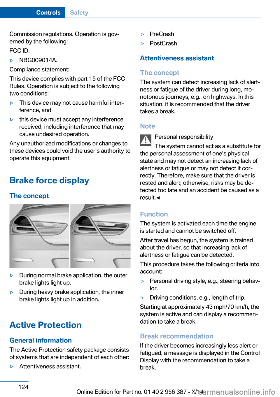
▷During normal brake application, the outer
brake lights light up.▷During heavy brake application, the inner
brake lights light up in addition.
Active Protection
General information
The Active Protection safety package consists
of systems that are independent of each other:
▷Attentiveness assistant.▷PreCrash▷PostCrash
Attentiveness assistant
The concept The system can detect increasing lack of alert‐
ness or fatigue of the driver during long, mo‐
notonous journeys, e.g., on highways. In this situation, it is recommended that the driver
takes a break.
Note Personal responsibility
The system cannot act as a substitute for
the personal assessment of one's physical
state and may not detect an increasing lack of
alertness or fatigue or may not detect it cor‐
rectly. Therefore, make sure that the driver is
rested and alert; otherwise, risks may be de‐
tected too late and an accident be caused as a
result.◀
Function
The system is activated each time the engine
is started and cannot be switched off.
After travel has begun, the system is trained
about the driver, so that increasing lack of
alertness or fatigue can be detected.
This procedure takes the following criteria into
account:
▷Personal driving style, e.g., steering behav‐
ior.▷Driving conditions, e.g., length of trip.
Starting at approximately 43 mph/70 km/h, the
system is active and can display a recommen‐
dation to take a break.
Break recommendation
If the driver becomes increasingly less alert or
fatigued, a message is displayed in the Control
Display with the recommendation to take a
break.
Seite 124ControlsSafety124
Online Edition for Part no. 01 40 2 956 387 - X/14
Page 133 of 247
▷When freeing vehicle from deep snow or
driving off from loose grounds.▷When driving with snow chains.
Deactivating/activating DTC Dynamic
Traction Control
Activating DTC Press button.
TRACTION is displayed in the instru‐
ment cluster and the indicator lamp for DSC
OFF lights up.
Deactivating DTC Press button again.
TRACTION and the DSC OFF indica‐
tor lamp go out.
Indicator/warning lights
If DTC is activated, TRACTION is displayed in
the instrument cluster.
The indicator lamp lights up: DTC Dy‐
namic Traction Control is activated.
xDrive xDrive is the all-wheel-drive system of your ve‐
hicle. Concerted action by the xDrive and DSC
further optimize traction and driving dynamics.
The xDrive all-wheel-drive system variably dis‐
tributes the drive forces to the front and rear
axles as demanded by the driving situation and
road surface.
HDC Hill Descent Control
The concept HDC is a downhill driving assistant that auto‐
matically controls vehicle speed on steep
downhill gradients. Without applying the
brakes, the vehicle moves at slightly more than
walking speed.
Hill Descent Control can be activated at
speeds below approx. 22 mph/35 km/h. When
driving downhill, the vehicle reduces its speed
to approx. walking speed and then keeps its
speed constant.
As long as there is active braking, the system
is on standby. The system does not brake the
vehicle during this time.
Only use HDC in low gears or in selector lever
position D or R.
Increasing or decreasing vehicle
speed
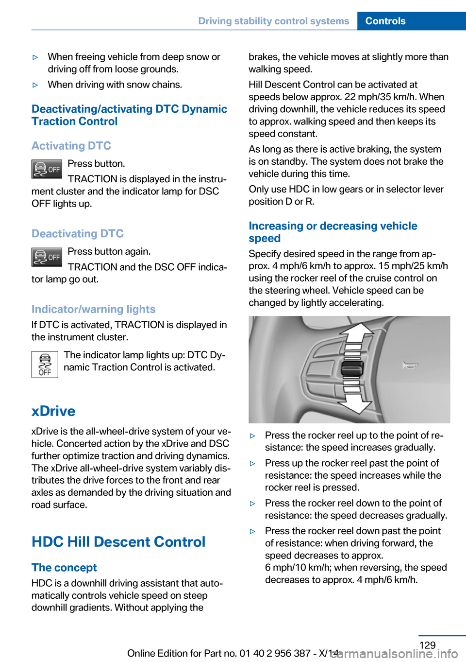
Specify desired speed in the range from ap‐
prox. 4 mph/6 km/h to approx. 15 mph/25 km/h
using the rocker reel of the cruise control on
the steering wheel. Vehicle speed can be
changed by lightly accelerating.▷Press the rocker reel up to the point of re‐
sistance: the speed increases gradually.▷Press up the rocker reel past the point of
resistance: the speed increases while the
rocker reel is pressed.▷Press the rocker reel down to the point of
resistance: the speed decreases gradually.▷Press the rocker reel down past the point
of resistance: when driving forward, the
speed decreases to approx.
6 mph/10 km/h; when reversing, the speed
decreases to approx. 4 mph/6 km/h.Seite 129Driving stability control systemsControls129
Online Edition for Part no. 01 40 2 956 387 - X/14
Page 158 of 247
Display on the Control Display
System activated/deactivatedSymbolMeaning Gray: the system is not available.
White: the system is available but
not activated. The system is activated.
System status
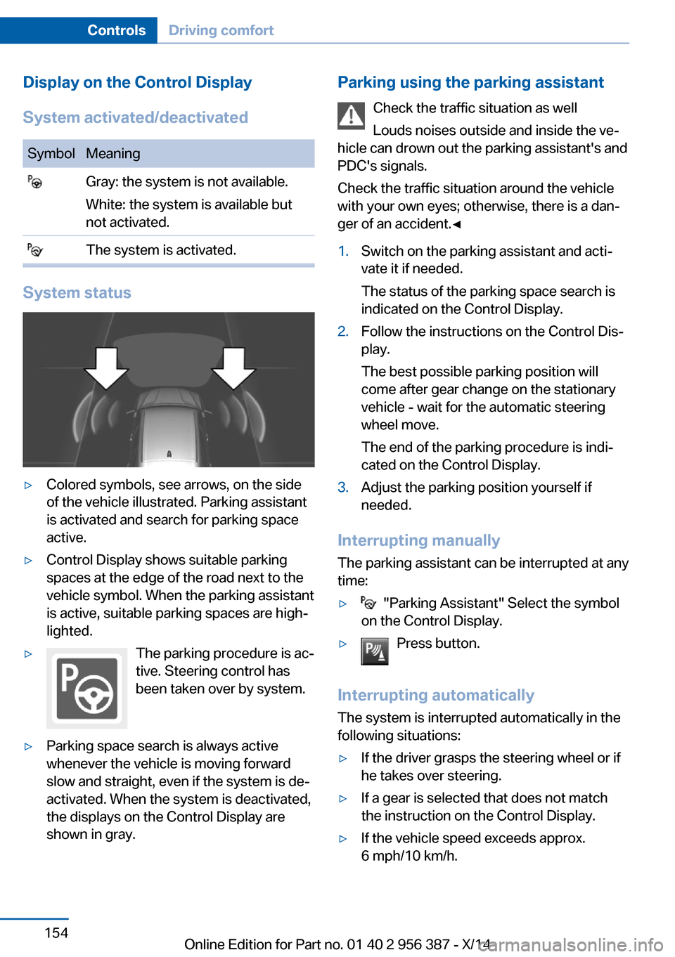
▷Colored symbols, see arrows, on the side
of the vehicle illustrated. Parking assistant
is activated and search for parking space
active.▷Control Display shows suitable parking
spaces at the edge of the road next to the
vehicle symbol. When the parking assistant
is active, suitable parking spaces are high‐
lighted.▷The parking procedure is ac‐
tive. Steering control has
been taken over by system.▷Parking space search is always active
whenever the vehicle is moving forward
slow and straight, even if the system is de‐
activated. When the system is deactivated,
the displays on the Control Display are
shown in gray.Parking using the parking assistant
Check the traffic situation as well
Louds noises outside and inside the ve‐
hicle can drown out the parking assistant's and
PDC's signals.
Check the traffic situation around the vehicle
with your own eyes; otherwise, there is a dan‐
ger of an accident.◀1.Switch on the parking assistant and acti‐
vate it if needed.
The status of the parking space search is
indicated on the Control Display.2.Follow the instructions on the Control Dis‐
play.
The best possible parking position will
come after gear change on the stationary
vehicle - wait for the automatic steering
wheel move.
The end of the parking procedure is indi‐
cated on the Control Display.3.Adjust the parking position yourself if
needed.
Interrupting manually
The parking assistant can be interrupted at any
time:
▷ "Parking Assistant" Select the symbol
on the Control Display.▷Press button.
Interrupting automatically
The system is interrupted automatically in the
following situations:
▷If the driver grasps the steering wheel or if
he takes over steering.▷If a gear is selected that does not match
the instruction on the Control Display.▷If the vehicle speed exceeds approx.
6 mph/10 km/h.Seite 154ControlsDriving comfort154
Online Edition for Part no. 01 40 2 956 387 - X/14
Page 160 of 247

Climate controlVehicle features and options
This chapter describes all standard, country-
specific and optional features offered with the
series. It also describes features that are not
necessarily available in your car, e. g., due to
the selected options or country versions. This
also applies to safety-related functions and
systems.
Automatic climate controlHints Sufficient ventilation
When remaining in the vehicle for an ex‐
tended period of time, ensure sufficient exter‐
nal ventilation. Do not continuously use recir‐
culated-air mode; otherwise the air quality in
the interior continuously worsens.◀
Climate control functions in detail
Manual air distribution Press button repeatedly to select a
program:▷Upper body region.▷Upper body region and footwell.▷Footwell.▷Windows and footwell.▷Windows, upper body region, and footwell.▷Windows: driver's side only.▷Windows and upper body region.
If the windows are fogged over, press the
AUTO button on the driver's side to utilize the
condensation sensor.
Temperature
Turn the ring to set the desired
temperature.
The automatic climate control achieves this
temperature as quickly as possible, if needed
by using the maximum cooling or heating li‐
dacity, and then keeps it constant.
Do not rapidly switch between different tem‐
perature settings. Otherwise, the automatic cli‐
mate control will not have sufficient time to ad‐
just the set temperature.
AUTO program Press button.
Air flow, air distribution and tempera‐
ture are controlled automatically.
Depending on the selected temperature,
AUTO intensity program and outside influen‐
ces, the air is directed to the windshield, side
windows, upper body, and into the footwell.
The cooling function, refer to page 157, is
switched on automatically with the AUTO pro‐
gram.
At the same time, a condensation sensor con‐
trols the program so as to prevent window
condensation as much as possible.
Intensity of the AUTO program
With the AUTO program activated, the auto‐
matic intensity control can be changed.
Press the left or right side of the but‐
ton: decrease or increase the inten‐
sity.
The selected intensity is shown on the display
of the automatic climate control.Seite 156ControlsClimate control156
Online Edition for Part no. 01 40 2 956 387 - X/14
Page 162 of 247
Rear window defrosterPress button.
The rear window defroster switches
off automatically after a certain period of time.
SYNC program Press button.
Current settings on the driver's side
for the temperature, air flow, air distribution,
and AUTO program are transferred to the front
passenger side.
The program is switched off if the settings on
the front passenger side are changed.
Residual heat
The heat stored in the engine is used to heat
the interior.
Functional requirement▷Up to 15 minutes after switching off the
engine.▷Warm engine.▷The battery is sufficiently charged.▷External temperature below 77 ℉/25 ℃.
The availability of the function is shown on the
display of the automatic climate control.
Switching on
1.Switch off the ignition.2. Press the right side of the button
on the driver's side.
The symbol appears on the automatic cli‐
mate Control Display.
The interior temperature, air volume and air
distribution can be adjusted with the ignition
switched on.
Switch off
At the lowest fan speed, press the left side of
the button on the driver's side.
The symbol on the display of the automatic
climate control flashes.
Switching the system on/off Switch off▷Complete system: Press and hold the left button on
the driver's side until the control
clicks off.▷On the front passenger side:
Press and hold the left button on
the front passenger side.
Switching on
Press any button except:
▷Rear window defroster.▷Left side of Air volume button.▷Seat heating.▷Seat ventilation.▷If necessary, SYNC program.
Microfilter/activated-charcoal filter
The microfilter removes dust and pollen from
the incoming air.
The activated-charcoal filter removes gaseous
pollutants from the outside air that enters the
vehicle.
This combined filter should be replaced during
scheduled maintenance, refer to page 209, of
your vehicle.
Seite 158ControlsClimate control158
Online Edition for Part no. 01 40 2 956 387 - X/14
Page 163 of 247
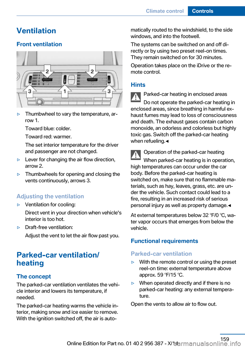
VentilationFront ventilation▷Thumbwheel to vary the temperature, ar‐
row 1.
Toward blue: colder.
Toward red: warmer.
The set interior temperature for the driver
and passenger are not changed.▷Lever for changing the air flow direction,
arrow 2.▷Thumbwheels for opening and closing the
vents continuously, arrows 3.
Adjusting the ventilation
▷Ventilation for cooling:
Direct vent in your direction when vehicle's
interior is too hot.▷Draft-free ventilation:
Adjust the vent to let the air flow past you.
Parked-car ventilation/
heating
The concept The parked-car ventilation ventilates the vehi‐
cle interior and lowers its temperature, if
needed.
The parked-car heating warms the vehicle in‐
terior, making snow and ice easier to remove.
With the ignition switched off, the air is auto‐
matically routed to the windshield, to the side
windows, and into the footwell.
The systems can be switched on and off di‐
rectly or by using two preset reel-on times.
They remain switched on for 30 minutes.
Operation takes place on the iDrive or the re‐ mote control.
Hints Parked-car heating in enclosed areas
Do not operate the parked-car heating in
enclosed areas, since breathing in harmful ex‐
haust fumes may lead to loss of consciousness
and death. The exhaust gases contain carbon
monoxide, an odorless and colorless but highly
toxic gas. Switch off the parked-car heating
when refueling.◀
Operation of the parked-car heating
When parked-car heating is in operation,
high temperatures can occur under the car
body. Before the parked-car heating is switched on, make sure that no flammable ma‐
terials, such as hay, leaves, grass, etc. are un‐
der the vehicle. Such contact could lead to a
fire, resulting in an increased risk of serious
personal injury as well as property damage.◀
At external temperatures below 32 ℉/0 ℃, wa‐
ter vapor occurs that emerges from below the
vehicle.
Functional requirements
Parked-car ventilation▷With the remote control or using the preset
reel-on time: external temperature above
approx. 59 ℉/15 ℃.▷When operated directly and if there is no
parked-car heating: any external tempera‐
ture.
Open the vents to allow air to flow out.
Seite 159Climate controlControls159
Online Edition for Part no. 01 40 2 956 387 - X/14