2014 BMW 550I SEDAN height
[x] Cancel search: heightPage 60 of 267
HintsManufacturer's information for child re‐
straint fixing systems
To select, mount and use child restraint fixing
systems, observe the information provided by
the system manufacturer; otherwise, the pro‐
tective effect can be impaired.◀
Ensuring the stability of the child seat
When installing child restraint fixing sys‐
tems, make sure that the child seat is securely
fastened to the backrest of the seat. The angle
of the backrest may need to be adjusted and,
where necessary, the headrest height may also need to be adjusted, or if possible removed.
Make sure that all backrests are securely
locked. Otherwise, the stability of the child
seat is limited, and there is an increased risk of
injury because of unexpected movement of the
rear seat backrest.◀
On the front passenger seat
Deactivating airbags
After installing a child restraint fixing system in
the front passenger seat, make sure that the
front, knee and side airbags on the front pas‐
senger side are deactivated.
Deactivate the front passenger airbags auto‐
matically, refer to page 105.
Deactivating the front passenger airbags
If a child restraint fixing system is used in
the front passenger seat, the front passenger
airbags must be deactivated; otherwise, there
is an increased risk of injury to the child when
the airbags are triggered, even with a child re‐
straint fixing system.◀
Seat position and height
Before installing a child restraint fixing system,
move the front passenger seat as far back as
possible and bring it up to medium height to
obtain the best possible position for the beltand to offer optimal protection in the event of
an accident.
If the upper fixing point of the safety belt is lo‐
cated before the belt guide of the child seat,
move the passenger seat carefully forward un‐
til the best possible belt guide position is
reached.
Child seat security
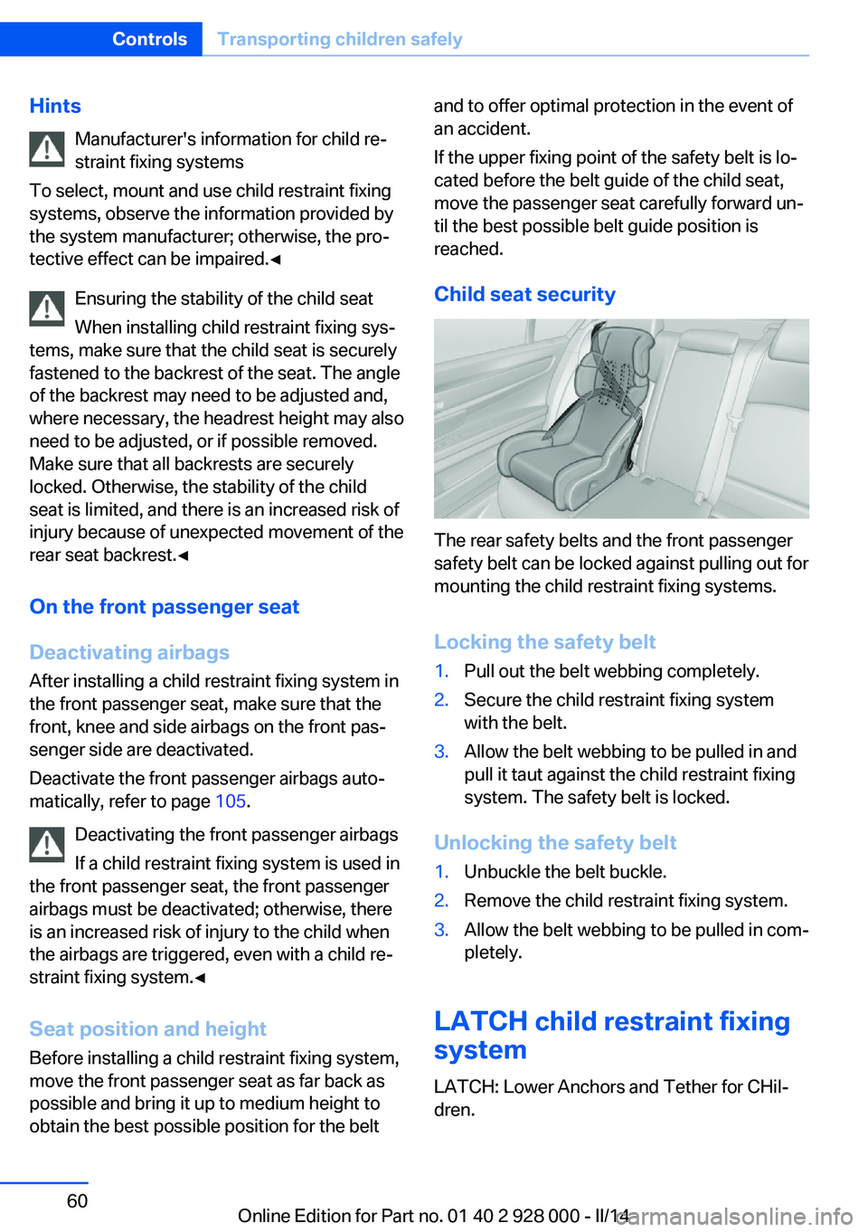
The rear safety belts and the front passenger
safety belt can be locked against pulling out for
mounting the child restraint fixing systems.
Locking the safety belt
1.Pull out the belt webbing completely.2.Secure the child restraint fixing system
with the belt.3.Allow the belt webbing to be pulled in and
pull it taut against the child restraint fixing
system. The safety belt is locked.
Unlocking the safety belt
1.Unbuckle the belt buckle.2.Remove the child restraint fixing system.3.Allow the belt webbing to be pulled in com‐
pletely.
LATCH child restraint fixing
system
LATCH: Lower Anchors and Tether for CHil‐dren.
Seite 60ControlsTransporting children safely60
Online Edition for Part no. 01 40 2 928 000 - II/14
Page 96 of 267
Head-up Display
The concept
This system projects important information
into the driver's field of vision, e.g., the speed.
The driver can get information without averting
his or her eyes from the road.
Display visibility The visibility of the displays in the Head-up
Display is influenced by the following factors:
▷Certain sitting positions.▷Objects on the cover of the Head-up Dis‐
play.▷Sunglasses with certain polarization filters.▷Wet roads.▷Unfavorable light conditions.
If the image is distorted, check the basic set‐
tings.
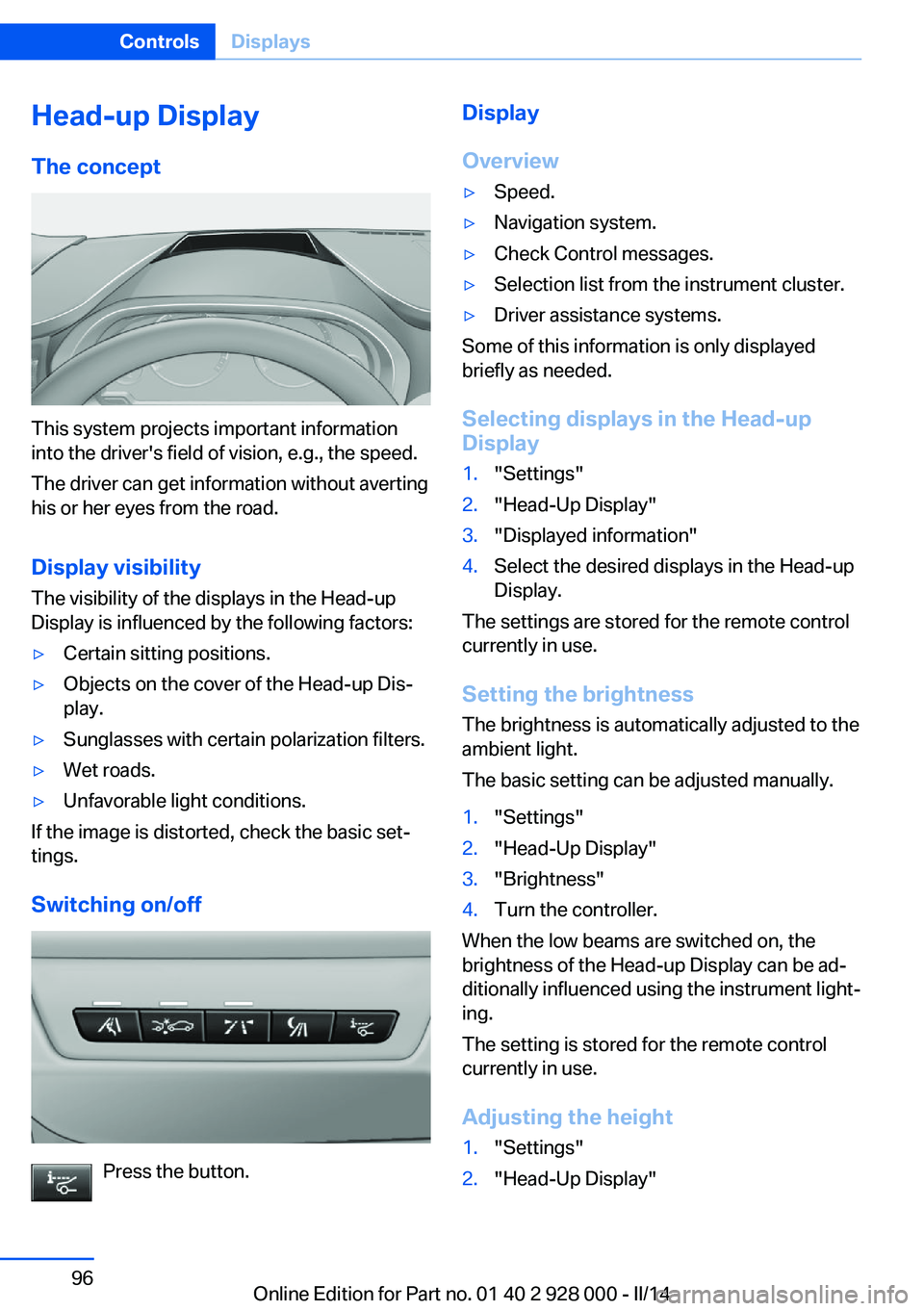
Switching on/off
Press the button.
Display
Overview▷Speed.▷Navigation system.▷Check Control messages.▷Selection list from the instrument cluster.▷Driver assistance systems.
Some of this information is only displayed
briefly as needed.
Selecting displays in the Head-up
Display
1."Settings"2."Head-Up Display"3."Displayed information"4.Select the desired displays in the Head-up
Display.
The settings are stored for the remote control
currently in use.
Setting the brightness
The brightness is automatically adjusted to the
ambient light.
The basic setting can be adjusted manually.
1."Settings"2."Head-Up Display"3."Brightness"4.Turn the controller.
When the low beams are switched on, the
brightness of the Head-up Display can be ad‐
ditionally influenced using the instrument light‐
ing.
The setting is stored for the remote control
currently in use.
Adjusting the height
1."Settings"2."Head-Up Display"Seite 96ControlsDisplays96
Online Edition for Part no. 01 40 2 928 000 - II/14
Page 97 of 267
3."Height"4.Turn the controller.
The setting is stored for the remote control
currently in use.
Setting the rotation
1."Settings"2."Head-Up Display"3."Rotation"4.Turn the controller.
The setting is stored for the remote control
currently in use.
Special windshield
The windshield is part of the system.
The shape of the windshield makes it possible
to display a precise image.
A film in the windshield prevents double im‐
ages from being displayed.
Therefore, have the special windshield re‐
placed by a service center only.
Seite 97DisplaysControls97
Online Edition for Part no. 01 40 2 928 000 - II/14
Page 155 of 267
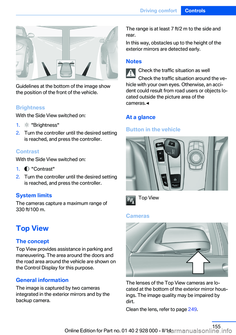
Guidelines at the bottom of the image show
the position of the front of the vehicle.
Brightness With the Side View switched on:
1. "Brightness"2.Turn the controller until the desired setting
is reached, and press the controller.
Contrast
With the Side View switched on:
1. "Contrast"2.Turn the controller until the desired setting
is reached, and press the controller.
System limits
The cameras capture a maximum range of
330 ft/100 m.
Top View
The concept Top View provides assistance in parking and
maneuvering. The area around the doors and
the road area around the vehicle are shown on
the Control Display for this purpose.
General information
The image is captured by two cameras
integrated in the exterior mirrors and by the
backup camera.
The range is at least 7 ft/2 m to the side and
rear.
In this way, obstacles up to the height of the
exterior mirrors are detected early.
Notes Check the traffic situation as well
Check the traffic situation around the ve‐
hicle with your own eyes. Otherwise, an acci‐
dent could result from road users or objects lo‐
cated outside the picture area of the
cameras.◀
At a glance
Button in the vehicle
Top View
Cameras
The lenses of the Top View cameras are lo‐
cated at the bottom of the exterior mirror hous‐
ings. The image quality may be impaired by
dirt.
Clean the lens, refer to page 249.
Seite 155Driving comfortControls155
Online Edition for Part no. 01 40 2 928 000 - II/14
Page 176 of 267
middle section is folded down. Otherwise, in‐
jury or damage may result.◀
Ensuring the stability of the child seat
When installing child restraint fixing sys‐
tems, make sure that the child seat is securely
fastened to the backrest of the seat. The angle
of the backrest may need to be adjusted and,
where necessary, the headrest height may also
need to be adjusted, or if possible removed.
Make sure that all backrests are securely
locked. Otherwise, the stability of the child
seat is limited, and there is an increased risk of
injury because of unexpected movement of the
rear seat backrest.◀
Opening Move the front seats to an upright posi‐
tion
Before folding down the rear backrests, ensure
that the front seats are moved forward slightly
and are in an upright position. Otherwise, the
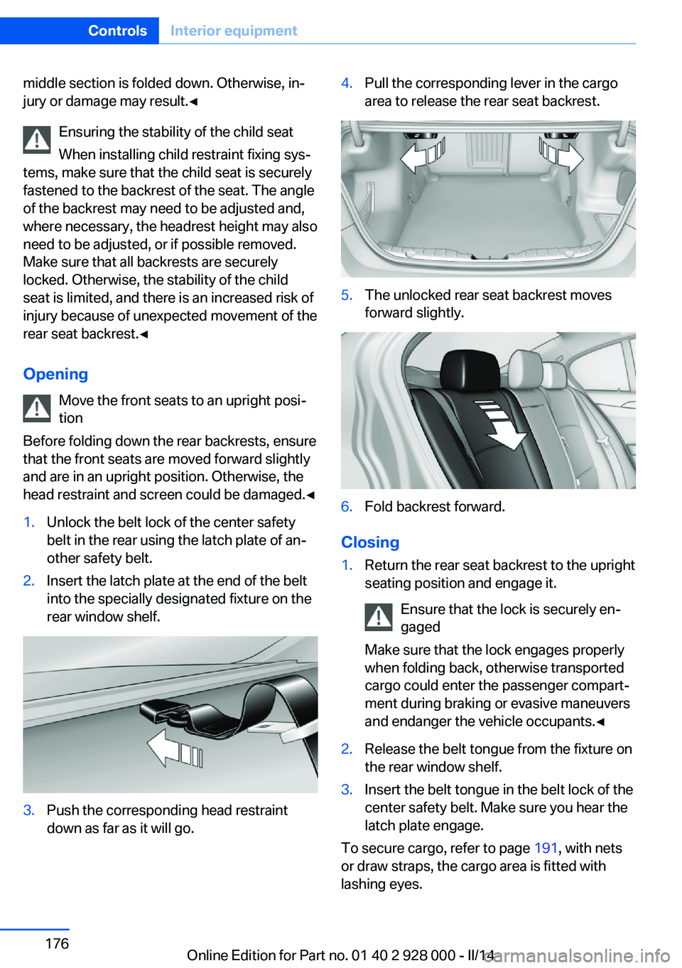
head restraint and screen could be damaged.◀1.Unlock the belt lock of the center safety
belt in the rear using the latch plate of an‐
other safety belt.2.Insert the latch plate at the end of the belt
into the specially designated fixture on the
rear window shelf.3.Push the corresponding head restraint
down as far as it will go.4.Pull the corresponding lever in the cargo
area to release the rear seat backrest.5.The unlocked rear seat backrest moves
forward slightly.6.Fold backrest forward.
Closing
1.Return the rear seat backrest to the upright
seating position and engage it.
Ensure that the lock is securely en‐
gaged
Make sure that the lock engages properly
when folding back, otherwise transported
cargo could enter the passenger compart‐
ment during braking or evasive maneuvers
and endanger the vehicle occupants.◀2.Release the belt tongue from the fixture on
the rear window shelf.3.Insert the belt tongue in the belt lock of the
center safety belt. Make sure you hear the
latch plate engage.
To secure cargo, refer to page 191, with nets
or draw straps, the cargo area is fitted with
lashing eyes.
Seite 176ControlsInterior equipment176
Online Edition for Part no. 01 40 2 928 000 - II/14
Page 188 of 267
Drive through calm water only and only if it is
not deeper than. 9.8 inches/25 cm and at this
height, no faster than walking speed, up to
6 mph/10 km/h.
Braking safely Your vehicle is equipped with ABS as a stand‐
ard feature.
Applying the brakes fully is the most effective
way of braking in situations when this is neces‐
sary.
The vehicle maintains steering responsive‐
ness. You can still avoid any obstacles with a
minimum of steering effort.
Pulsation of the brake pedal and sounds from
the hydraulic circuits indicate that ABS is in its
active mode.
Objects within the range of movement
of the pedals
No objects in the area around the pedals
Keep floor mats, carpets, and any other
objects out of the area of motion of the pedals;
otherwise, the function of the pedals could be
impeded while driving and create the risk of an
accident.
Do not place additional floor mats over existing
mats or other objects.
Only use floor mats that have been approved
for the vehicle and can be properly fixed in
place.
Ensure that the floor mats are securely fas‐
tened again after they were removed for clean‐
ing, for example.◀
Driving in wet conditions
When roads are wet coated with road salt or
there is heavy rain, briefly exert gentle pres‐
sure on the brake pedal every few miles.
Ensure that this action does not endanger
other road users.
The heat generated in this process helps dry
the brake discs and pads.In this way braking efficiency will be available
when you need it.
Hills
Drive long or steep downhill gradients in the
gear in which the least braking is required.
Otherwise, the brake system may overheat, re‐ sulting in a reduction in the brake system effi‐ciency.
You can increase the engine's braking effect
by shifting down, going all the way to first gear,
if necessary.
Avoid load on the brakes
Avoid placing excessive load on the
brake system. Light but consistent brake pres‐
sure can lead to high temperatures, brake wear
and possibly even brake failure.◀
Do not drive in neutral
Do not drive in neutral or with the engine
stopped, as doing so disables engine braking.
In addition, steering and brake assist are un‐
available with the engine stopped.◀
Brake disc corrosion
The corrosion on the brake discs and the con‐
tamination on the brake pads are furthered by:▷Low mileage.▷Extended periods when the vehicle is not
used at all.▷Infrequent use of the brakes.
Corrosion occurs when the minimum pressure
that must be exerted by the pads during brake
applications to clean the discs is not reached.
Should corrosion form on the brake discs, the
brakes will tend to respond with a pulsating ef‐
fect that generally cannot be corrected.
Condensation under the parked
vehicle
When using the automatic climate control,
condensation water develops that exits under‐
neath the vehicle.
Seite 188Driving tipsThings to remember when driving188
Online Edition for Part no. 01 40 2 928 000 - II/14
Page 220 of 267
Temperature grade for this tire
The temperature grade for this tire is es‐
tablished for a tire that is properly inflated and
not overloaded. Excessive speed, underinfla‐
tion, or excessive loading, either separately or
in combination, can cause heat buildup and
possible tire failure.
If necessary, have the vehicle towed.◀
RSC – Run-flat tires
Run-flat tires, refer to page 222, are labeled
with a circular symbol containing the letters RSC marked on the sidewall.
M+S
Winter and all-season tires with better cold
weather performance than summer tires.
Tire treadSummer tires
Do not drive with a tire tread depth of less than
0.12 in/3 mm.
There is an increased danger of hydroplaning if
the tread depth is less than 0.12 in/3 mm.
Winter tires
Do not drive with a tire tread depth of less than
0.16 in/4 mm.
Below a tread depth of 0.16 in/4 mm, tires are
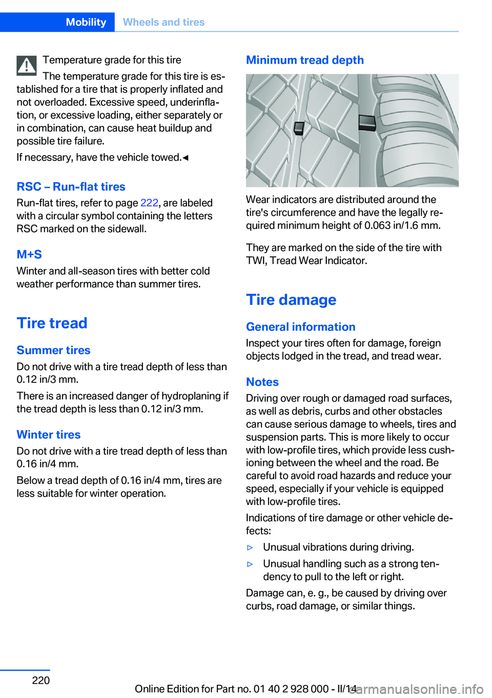
less suitable for winter operation.Minimum tread depth
Wear indicators are distributed around the
tire's circumference and have the legally re‐
quired minimum height of 0.063 in/1.6 mm.
They are marked on the side of the tire with
TWI, Tread Wear Indicator.
Tire damage
General information
Inspect your tires often for damage, foreign
objects lodged in the tread, and tread wear.
Notes
Driving over rough or damaged road surfaces,
as well as debris, curbs and other obstacles can cause serious damage to wheels, tires and
suspension parts. This is more likely to occur
with low-profile tires, which provide less cush‐
ioning between the wheel and the road. Be
careful to avoid road hazards and reduce your
speed, especially if your vehicle is equipped
with low-profile tires.
Indications of tire damage or other vehicle de‐
fects:
▷Unusual vibrations during driving.▷Unusual handling such as a strong ten‐
dency to pull to the left or right.
Damage can, e. g., be caused by driving over
curbs, road damage, or similar things.
Seite 220MobilityWheels and tires220
Online Edition for Part no. 01 40 2 928 000 - II/14
Page 225 of 267
Never reach into the engine compart‐
ment
Never reach into the intermediate spaces or
gaps in the engine compartment. Otherwise,
there is risk of injury, e.g., from rotating or hot
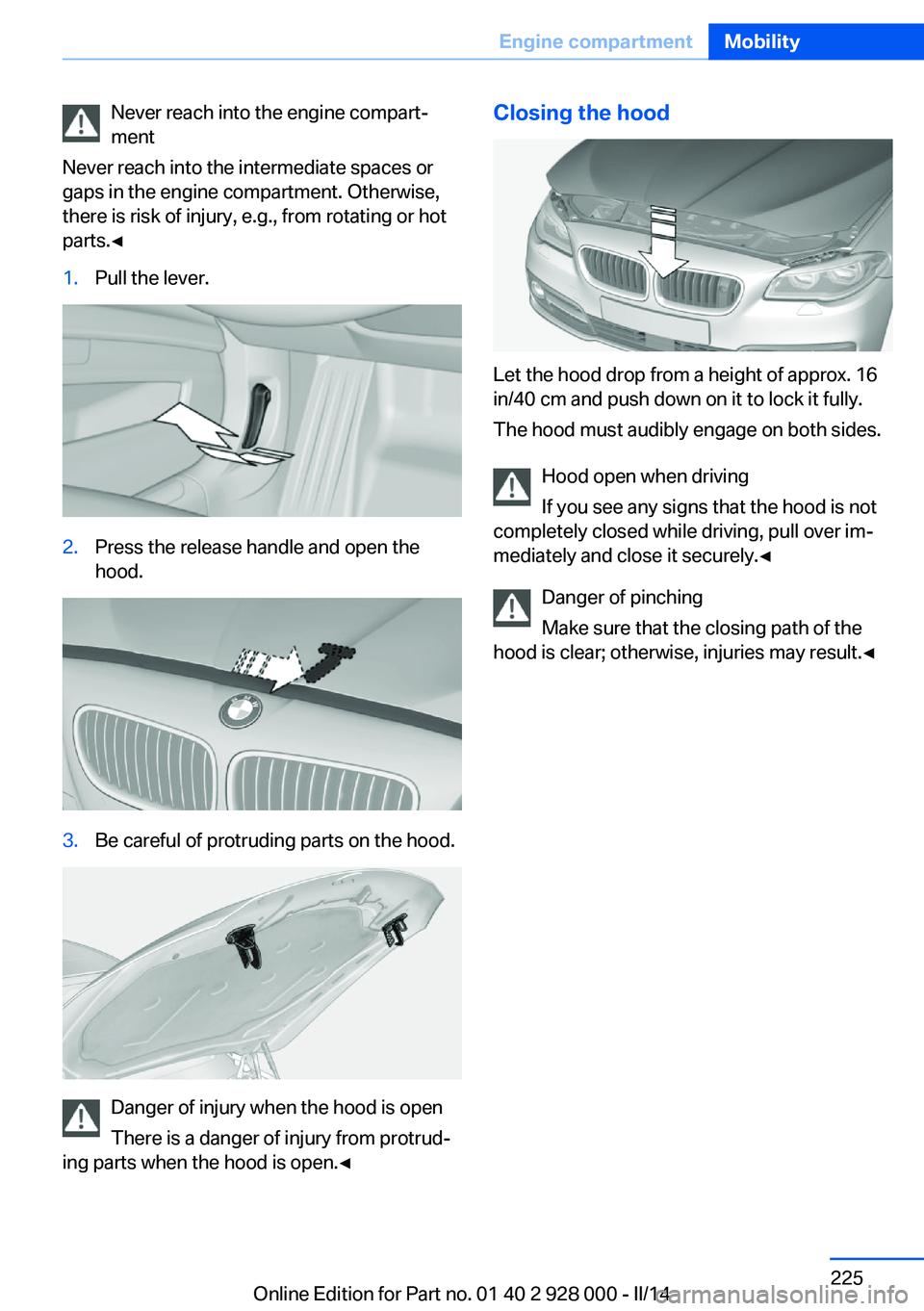
parts.◀1.Pull the lever.2.Press the release handle and open the
hood.3.Be careful of protruding parts on the hood.
Danger of injury when the hood is open
There is a danger of injury from protrud‐
ing parts when the hood is open.◀
Closing the hood
Let the hood drop from a height of approx. 16
in/40 cm and push down on it to lock it fully.
The hood must audibly engage on both sides.
Hood open when driving
If you see any signs that the hood is not
completely closed while driving, pull over im‐
mediately and close it securely.◀
Danger of pinching
Make sure that the closing path of the
hood is clear; otherwise, injuries may result.◀
Seite 225Engine compartmentMobility225
Online Edition for Part no. 01 40 2 928 000 - II/14