2014 BMW 550I GRAN TURISMO service
[x] Cancel search: servicePage 108 of 251
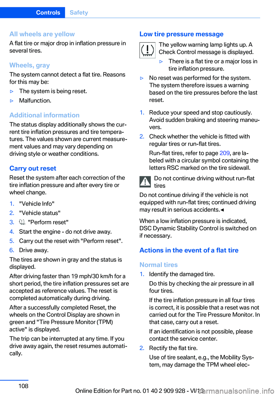
All wheels are yellowA flat tire or major drop in inflation pressure in
several tires.
Wheels, gray The system cannot detect a flat tire. Reasons
for this may be:▷The system is being reset.▷Malfunction.
Additional information
The status display additionally shows the cur‐
rent tire inflation pressures and tire tempera‐
tures. The values shown are current measure‐
ment values and may vary depending on
driving style or weather conditions.
Carry out reset Reset the system after each correction of the
tire inflation pressure and after every tire or
wheel change.
1."Vehicle Info"2."Vehicle status"3. "Perform reset"4.Start the engine - do not drive away.5.Carry out the reset with "Perform reset".6.Drive away.
The tires are shown in gray and the status is
displayed.
After driving faster than 19 mph/30 km/h for a
short period, the tire inflation pressures set are
accepted as reference values. The reset is
completed automatically during driving.
After a successfully completed Reset, the
wheels on the Control Display are shown in
green and "Tire Pressure Monitor (TPM)
active" is displayed.
The trip can be interrupted at any time. If you
drive away again, the reset resumes automati‐
cally.
Low tire pressure message
The yellow warning lamp lights up. A
Check Control message is displayed.▷There is a flat tire or a major loss in
tire inflation pressure.▷No reset was performed for the system.
The system therefore issues a warning
based on the tire pressures before the last
reset.1.Reduce your speed and stop cautiously.
Avoid sudden braking and steering maneu‐
vers.2.Check whether the vehicle is fitted with
regular tires or run-flat tires.
Run-flat tires, refer to page 209, are la‐
beled with a circular symbol containing the
letters RSC marked on the tire sidewall.
Do not continue driving without run-flat
tires
Do not continue driving if the vehicle is not
equipped with run-flat tires; continued driving
may result in serious accidents.◀
When a low inflation pressure is indicated,
DSC Dynamic Stability Control is switched on
if necessary.
Actions in the event of a flat tire
Normal tires
1.Identify the damaged tire.
Do this by checking the air pressure in all
four tires.
If the tire inflation pressure in all four tires
is correct, it is possible that a reset was not
carried out for the Tire Pressure Monitor. In
that case, carry out a reset.
If an identification is not possible, please
contact the service center.2.Rectify the flat tire.
Use of tire sealant, e.g., the Mobility Sys‐
tem, may damage the TPM wheel elec‐Seite 108ControlsSafety108
Online Edition for Part no. 01 40 2 909 928 - VI/13
Page 109 of 251
tronics. In this case, have the electronics
checked at the next opportunity and have
them replaced if necessary.
Run-flat tires
Maximum speed
You can continue driving with a damaged tire
at speeds up to 50 mph/80 km/h.
Continued driving with a flat tire
If continuing to drive with a damaged tire:
1.Avoid sudden braking and steering maneu‐
vers.2.Do not exceed a speed of 50 mph/80 km/h.3.Check the air pressure in all four tires at
the next opportunity.
If the tire inflation pressure in all four tires
is correct, it is possible that a reset was not
carried out for the Tire Pressure Monitor. In
that case, carry out a reset.
Possible driving distance with complete loss of
tire inflation pressure:
The possible driving distance after a loss of tire
inflation pressure depends on the cargo load
and the driving style and conditions.
For a vehicle containing an average load, the
possible driving distance is approx.
50 miles/80 km.
When the vehicle is driven with a damaged tire,
its handling characteristics change, e.g., re‐
duced lane stability during braking, a longer
braking distance, and altered self-steering
properties. Adjust your driving style accord‐
ingly. Avoid abrupt steering maneuvers or driv‐
ing over obstacles, e.g., curbs, potholes, etc.
Because the possible driving distance de‐
pends on how the vehicle is used during the
trip, the actual distance may be smaller or
greater depending on the driving speed, road
conditions, external temperature, cargo load,
etc.
Continued driving with a flat tire
Drive moderately and do not exceed a
speed of 50 mph/80 km/h.
A loss of tire inflation pressure results in a
change in the handling characteristics, e.g., re‐
duced lane stability during braking, a longer
braking distance and altered self-steering
properties.◀
Final tire failure
Vibrations or loud noises while driving
can indicate the final failure of the tire. Reduce
speed and stop; otherwise, pieces of the tire
could come loose and cause an accident. Do
not continue driving, and contact your service
center.◀
Required inflation pressure check
message
A Check Control message is displayed.
Check the tire inflation pressure and carry out
a reset of the system.
In some cases, a wheel was changed without
having carried out a reset.
System limits
The system does not function properly if a re‐
set has not been carried out, e.g., a flat tire is
reported even though the tire inflation pres‐
sures are correct.
The tire pressure depends on the temperature
of the tire. If the tire temperature rises, e.g.,
due to driving or because of the heat of the
Sun, the tire inflation pressure increases also.
The tire pressure is reduced when the tire
temperature falls again. This behavior may
cause a warning to be issued if temperatures
fall very sharply.
Malfunction The yellow warning lamp flashes and
then lights up continuously. A CheckSeite 109SafetyControls109
Online Edition for Part no. 01 40 2 909 928 - VI/13
Page 110 of 251
Control message is displayed. No flat tire or
loss of tire pressure can be detected.
Display in the following situations:▷A wheel without TPM electronics is fitted:
have the service center check it if neces‐
sary.▷Malfunction: have the system checked by
your service center.▷TPM was unable to complete the reset.
Reset the system again.▷Disturbance by systems or devices with
the same radio frequency: after leaving the
area of the disturbance, the system auto‐
matically becomes active again.
Declaration according to NHTSA/
FMVSS 138 Tire Pressure Monitoring
System
Each tire, including the spare (if provided)
should be checked monthly when cold and in‐
flated to the inflation pressure recommended
by the vehicle manufacturer on the vehicle
placard or tire inflation pressure label. (If your
vehicle has tires of a different size than the size
indicated on the vehicle placard or tire inflation
pressure label, you should determine the
proper tire inflation pressure for those tires.)
As an added safety feature, your vehicle has
been equipped with a tire pressure monitoring
system (TPMS) that illuminates a low tire pres‐
sure telltale when one or more of your tires is
significantly under-inflated. Accordingly, when
the low tire pressure telltale illuminates, you
should stop and check your tires as soon as
possible, and inflate them to the proper pres‐
sure. Driving on a significantly under-inflated
tire causes the tire to overheat and can lead to
tire failure. Under-inflation also reduces fuel ef‐
ficiency and tire tread life, and may affect the
vehicle's handling and stopping ability. Please
note that the TPMS is not a substitute for
proper tire maintenance, and it is the driver's
responsibility to maintain correct tire pressure,
even if under-inflation has not reached the
level to trigger illumination of the TPMS low
tire pressure telltale. Your vehicle has also
been equipped with a TPMS malfunction indi‐
cator to indicate when the system is not oper‐
ating properly. The TPMS malfunction indica‐
tor is combined with the low tire pressure
telltale. When the system detects a malfunc‐
tion, the telltale will flash for approximately one
minute and then remain continuously illumi‐
nated. This sequence will continue upon sub‐
sequent vehicle start-ups as long as the mal‐
function exists. When the malfunction indicator
is illuminated, the system may not be able to
detect or signal low tire pressure as intended.
TPMS malfunctions may occur for a variety of
reasons, including the installation of replace‐
ment or alternate tires or wheels on the vehicle
that prevent the TPMS from functioning prop‐
erly. Always check the TPMS malfunction tell‐
tale after replacing one or more tires or wheels
on your vehicle to ensure that the replacement
or alternate tires and wheels allow the TPMS
to continue to function properly.
Intelligent Safety
The concept Depending on how the vehicle is equipped, In‐
telligent Safety consists of one or more of the
following systems, which can help to avoid an
imminent collision. These systems are active
automatically every time the engine is started
using the Start/Stop button:▷Collision warning, refer to page 111.▷Pedestrian warning, refer to page 116.
Note
Personal responsibility
The system does not serve as a substi‐
tute for the driver's personal judgment of the
traffic situation.
Seite 110ControlsSafety110
Online Edition for Part no. 01 40 2 909 928 - VI/13
Page 132 of 251
The system ensures consistent comfort by
keeping spring travel constant in all driving sit‐
uations.
Malfunction
A Check Control message is displayed. A mal‐ function has occurred in the self-leveling sus‐
pension. Vehicle handling may be altered and
driving comfort may be noticeably reduced.
Visit your nearest service center.
Driving Dynamics ControlThe concept
The Driving Dynamics Control can be used to
adjust the driving dynamics of the vehicle. For
this purpose various programs are available for
selection that are activated via the two buttons
of the Driving Dynamics Control and the DSC
OFF-button.
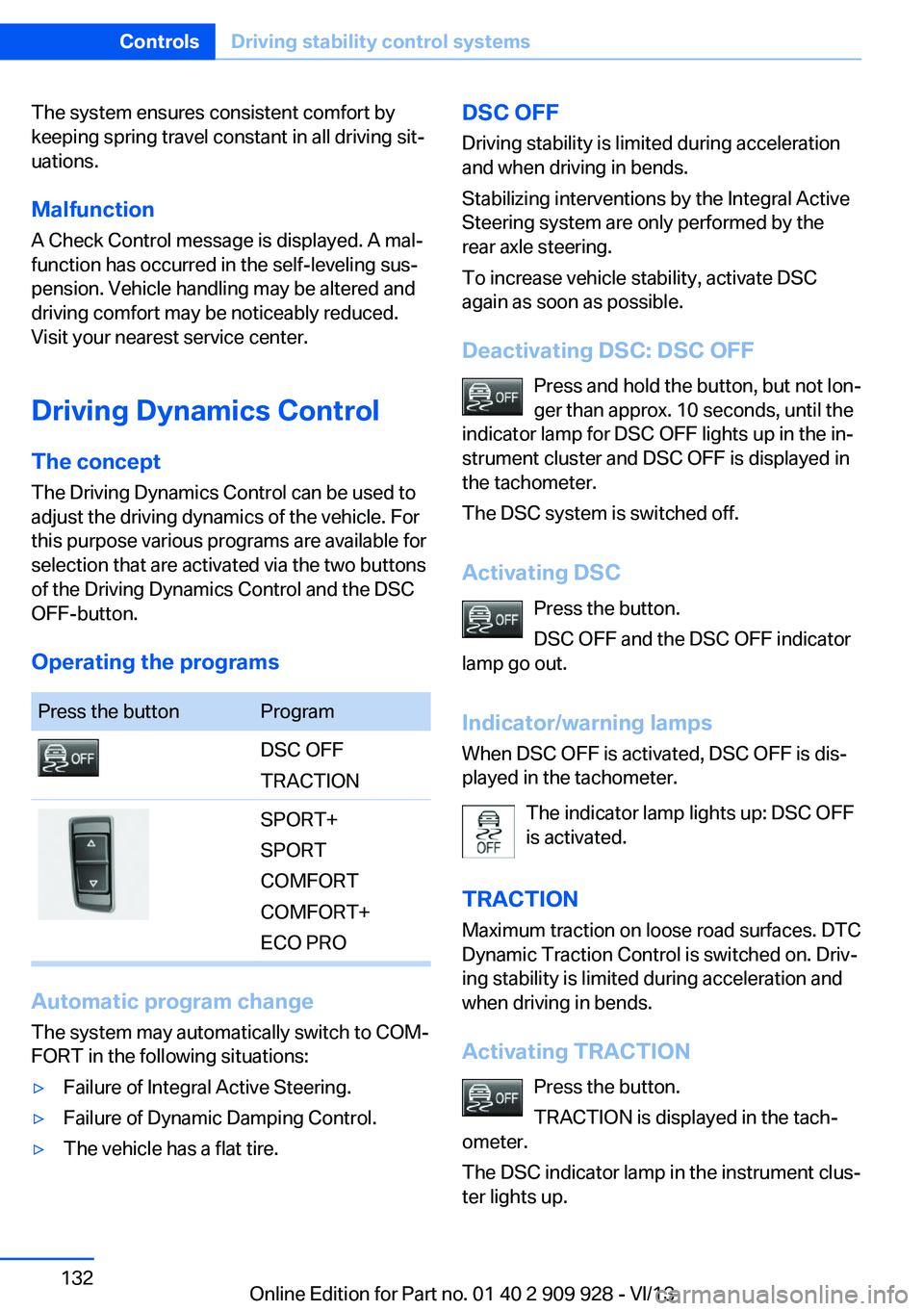
Operating the programsPress the buttonProgramDSC OFF
TRACTIONSPORT+
SPORT
COMFORT
COMFORT+
ECO PRO
Automatic program change
The system may automatically switch to COM‐
FORT in the following situations:
▷Failure of Integral Active Steering.▷Failure of Dynamic Damping Control.▷The vehicle has a flat tire.DSC OFF
Driving stability is limited during acceleration
and when driving in bends.
Stabilizing interventions by the Integral Active
Steering system are only performed by the
rear axle steering.
To increase vehicle stability, activate DSC
again as soon as possible.
Deactivating DSC: DSC OFF Press and hold the button, but not lon‐
ger than approx. 10 seconds, until the
indicator lamp for DSC OFF lights up in the in‐
strument cluster and DSC OFF is displayed in
the tachometer.
The DSC system is switched off.
Activating DSC Press the button.
DSC OFF and the DSC OFF indicator
lamp go out.
Indicator/warning lamps
When DSC OFF is activated, DSC OFF is dis‐
played in the tachometer.
The indicator lamp lights up: DSC OFF
is activated.
TRACTION Maximum traction on loose road surfaces. DTC
Dynamic Traction Control is switched on. Driv‐
ing stability is limited during acceleration and
when driving in bends.
Activating TRACTION Press the button.
TRACTION is displayed in the tach‐
ometer.
The DSC indicator lamp in the instrument clus‐
ter lights up.Seite 132ControlsDriving stability control systems132
Online Edition for Part no. 01 40 2 909 928 - VI/13
Page 160 of 251
Adjusting the height1."Settings"2."Head-Up Display"3."Height"4.Turn the controller.
The setting is stored for the remote control
currently in use.
Setting the rotation
1."Settings"2."Head-Up Display"3."Rotation"4.Turn the controller.
The setting is stored for the remote control
currently in use.
Special windshield
The windshield is part of the system.
The shape of the windshield makes it possible
to display a precise image.
A film in the windshield prevents double im‐
ages from being displayed.
Therefore, have the special windshield re‐
placed by a service center only.
Distance information The conceptThe system displays a symbol in the Head-up
Display to indicate that the distance behind the
vehicle in front is not sufficient.
General information The distance is determined by the radar sen‐
sor of the Active Cruise Control.
Hints
Personal responsibility
The display does not relieve the driver of
the responsibility to adapt his or her distance
and driving style to the traffic conditions. Main‐
tain the prescribed safety distance.◀
At a glance
Radar sensor
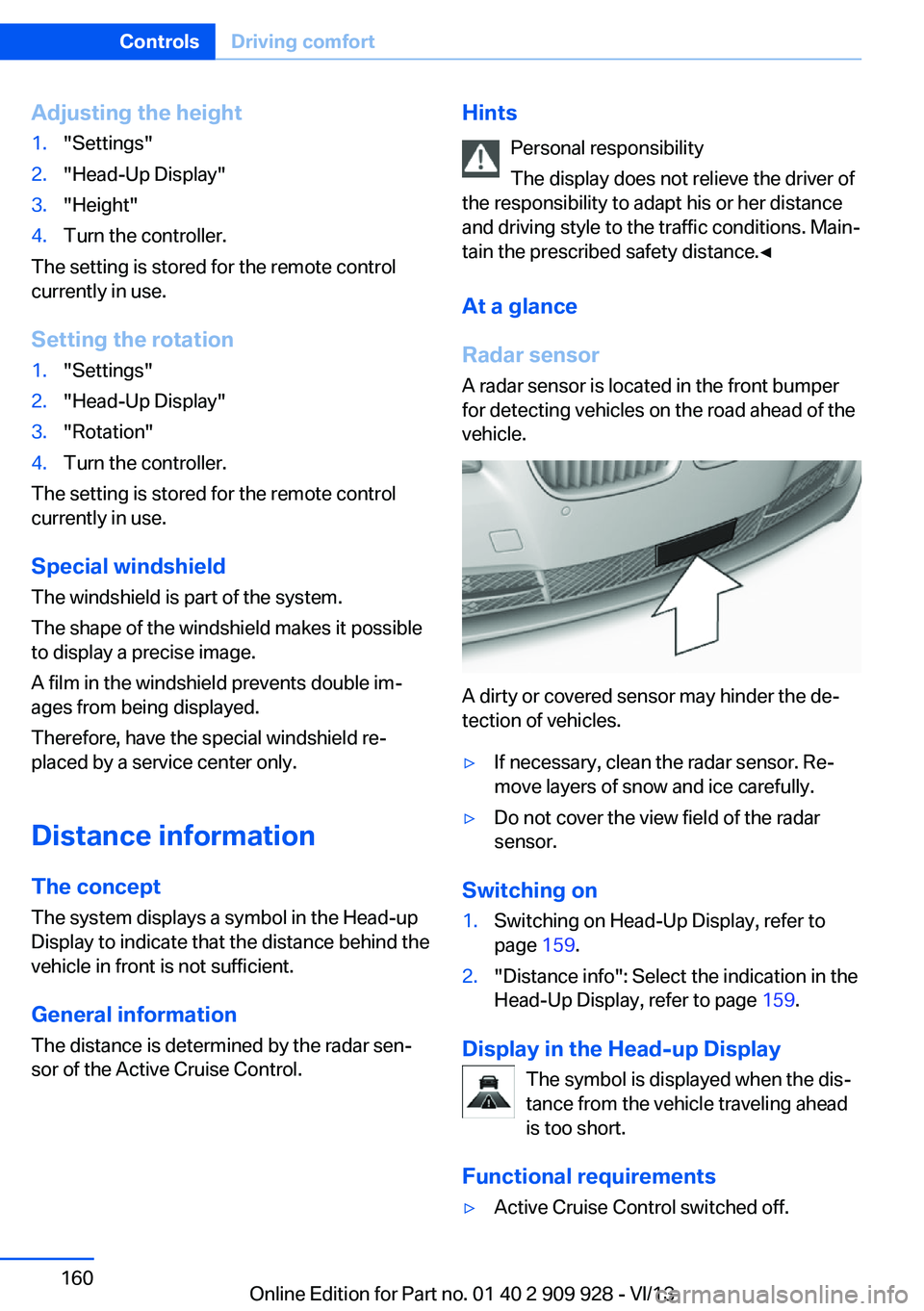
A radar sensor is located in the front bumper
for detecting vehicles on the road ahead of the
vehicle.
A dirty or covered sensor may hinder the de‐
tection of vehicles.
▷If necessary, clean the radar sensor. Re‐
move layers of snow and ice carefully.▷Do not cover the view field of the radar
sensor.
Switching on
1.Switching on Head-Up Display, refer to
page 159.2."Distance info": Select the indication in the
Head-Up Display, refer to page 159.
Display in the Head-up Display
The symbol is displayed when the dis‐
tance from the vehicle traveling ahead
is too short.
Functional requirements
▷Active Cruise Control switched off.Seite 160ControlsDriving comfort160
Online Edition for Part no. 01 40 2 909 928 - VI/13
Page 169 of 251
Interior equipmentVehicle equipmentAll standard, country-specific and optional
equipment that is offered in the model series is
described in this chapter. Therefore, equip‐
ment is also described that is not available in a
vehicle, e. g., because of the selected optional
equipment or country variant. This also applies
for safety-related functions and systems.
Integrated universal remote
control
The conceptThe integrated universal remote control can
operate up to 3 functions of remote-controlled
systems such as garage door drives or lighting
systems. The integrated universal remote con‐
trol replaces up to 3 different hand-held trans‐
mitters. To operate the remote control, the
buttons on the interior rearview mirror must be
programmed with the desired functions. The
hand-held transmitter for the particular system
is required in order to program the remote con‐
trol.
During programming
During programming and before activat‐
ing a device using the integrated universal re‐
mote control, ensure that there are no people,
animals, or objects in the range of movement
of the remote-controlled device; otherwise,
there is a risk of injury or damage.
Also follow the safety instructions of the hand-
held transmitter.◀
Before selling the vehicle, delete the stored
functions for the sake of security.Compatibility
If this symbol is printed on the packag‐
ing or in the instructions of the system
to be controlled, the system is gener‐
ally compatible with the integrated universal
remote control.
If you have any questions, please contact:▷Your service center.▷www.homelink.com on the Internet.
HomeLink is a registered trademark of John‐
son Controls, Inc.
Controls on the interior rearview
mirror
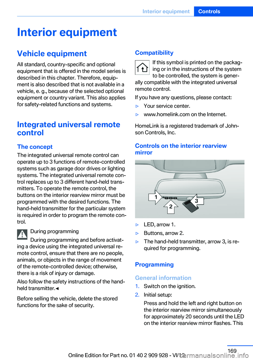
▷LED, arrow 1.▷Buttons, arrow 2.▷The hand-held transmitter, arrow 3, is re‐
quired for programming.
Programming
General information
1.Switch on the ignition.2.Initial setup:
Press and hold the left and right button on
the interior rearview mirror simultaneously
for approximately 20 seconds until the LED
on the interior rearview mirror flashes. ThisSeite 169Interior equipmentControls169
Online Edition for Part no. 01 40 2 909 928 - VI/13
Page 191 of 251
Use coasting conditions
When approaching a red light, take your foot
off the accelerator and let the vehicle coast to
a halt.
On a downhill gradient, take your foot off the
accelerator and let the vehicle roll.
The flow of fuel is interrupted while coasting.
Switch off the engine during longer stops
Switch off the engine during longer stops, e.g.,
at traffic lights, railroad crossings or in traffic
congestion.
Automatic Engine Start/Stop Function The Auto Start/Stop function of your vehicle
automatically switches off the engine during a
stop.
If the engine is switched off and then restarted
rather than leaving the engine running con‐
stantly, fuel consumption and emissions are
reduced. Savings can begin within a few sec‐
onds of switching off the engine.
Using this system can cause certain compo‐
nents of the vehicle to become worn prema‐
turely.
In addition, fuel consumption is also deter‐
mined by other factors, such as driving style,
road conditions, maintenance or environmental
factors.
Switch off any functions that
are not currently needed
Functions such as seat heating and the rear
window defroster require a lot of energy and
consume additional fuel, especially in city and
stop-and-go traffic.
Therefore, switch off these functions if they
are not actually needed.Have maintenance carried
out
Have vehicles maintained regularly to achieve
optimal vehicle economy and operating life.
Have the maintenance carried out by your
service center.
Please also note the BMW Maintenance Sys‐
tem, refer to page 216.
ECO PRO
The concept ECO PRO supports a driving style that saves
on fuel consumption. For this purpose, the en‐
gine control and comfort functions, e. g. the
climate control output, are adjusted.
The extension of the range that is achieved as
a result can be displayed in the instrument
cluster.
At a glance
The system includes the following
EfficientDynamics functions and displays:▷ECO PRO bonus range, refer to page 192.▷ECO PRO tips driving instruction, refer to
page 193▷ECO PRO climate control, refer to
page 192.
Activating ECO PRO
Press button repeatedly until ECO
PRO is displayed in the instrument
cluster.
Configuring ECO PRO
Via the Driving Dynamics Control
1.Activate ECO PRO.2."Configure ECO PRO"3.Configure the program.Seite 191Saving fuelDriving tips191
Online Edition for Part no. 01 40 2 909 928 - VI/13
Page 201 of 251
Wheels and tiresVehicle equipment
All standard, country-specific and optional
equipment that is offered in the model series is
described in this chapter. Therefore, equip‐
ment is also described that is not available in a
vehicle, e. g., because of the selected optional
equipment or country variant. This also applies
for safety-related functions and systems.
Tire inflation pressure Safety information
The tire characteristics and tire inflation pres‐
sure influence the following:▷The service life of the tires.▷Road safety.▷Driving comfort.
Checking the pressure
Only check the tire inflation pressure when the
tires are cold. This means after driving no more
than 1.25 miles/2 km or when the vehicle has
been parked for at least 2 hours. When the
tires are warm, the tire inflation pressure is
higher.
Check the tire inflation pressure regularly
Regularly check the tire inflation pres‐
sure, and correct it as needed: at least twice a
month and before a long trip. If you fail to ob‐
serve this precaution, you may be driving on
tires with incorrect tire pressures, a condition
that may not only compromise your vehicle's
driving stability, but also lead to tire damage
and the risk of an accident.◀
After correcting the tire inflation pressure:
▷Reinitialize the Flat Tire Monitor.▷Reinitialize the Tire Pressure Monitor.Pressure specifications The tire inflation pressure table, refer to
page 202, contains all pressure specifications
for the specified tire sizes at the ambient tem‐
perature. Pressure specifications apply to ap‐
proved tire sizes and recommended tire
brands. This information can be obtained from
your service center.
To identify the correct tire inflation pressure,
please note the following:▷Tire sizes of your vehicle.▷Maximum permitted driving speed.
Tire inflation pressures up to
100 mph/160 km/h
For speeds of up to 100 mph/160 km/h and for
optimum driving comfort, note the pressure
values in the tire inflation pressure table, refer
to page 202, and adjust as necessary.
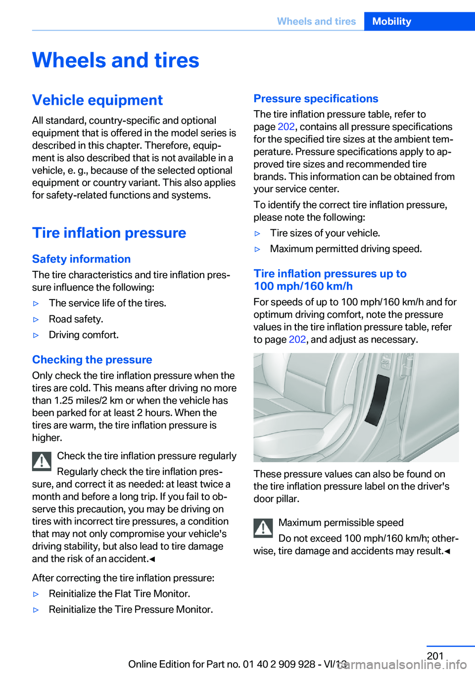
These pressure values can also be found on
the tire inflation pressure label on the driver's
door pillar.
Maximum permissible speed
Do not exceed 100 mph/160 km/h; other‐
wise, tire damage and accidents may result.◀
Seite 201Wheels and tiresMobility201
Online Edition for Part no. 01 40 2 909 928 - VI/13