2014 BMW 528I XDRIVE warning
[x] Cancel search: warningPage 122 of 267

Although both the shape and the heat radiation
are analyzed, false warnings cannot be ruled
out.
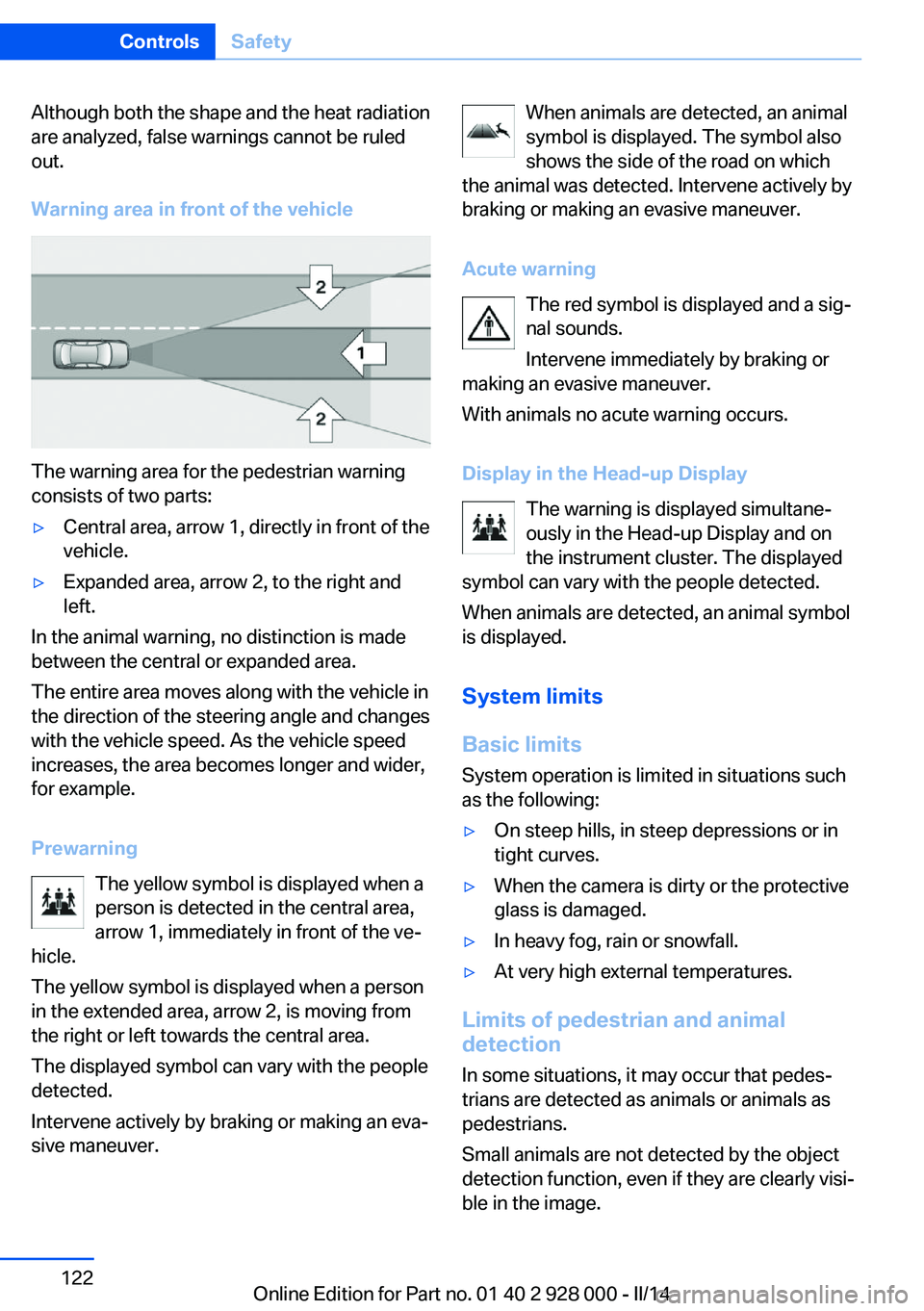
Warning area in front of the vehicle
The warning area for the pedestrian warning
consists of two parts:
▷Central area, arrow 1, directly in front of the
vehicle.▷Expanded area, arrow 2, to the right and
left.
In the animal warning, no distinction is made
between the central or expanded area.
The entire area moves along with the vehicle in
the direction of the steering angle and changes
with the vehicle speed. As the vehicle speed
increases, the area becomes longer and wider,
for example.
Prewarning The yellow symbol is displayed when aperson is detected in the central area,
arrow 1, immediately in front of the ve‐
hicle.
The yellow symbol is displayed when a person
in the extended area, arrow 2, is moving from
the right or left towards the central area.
The displayed symbol can vary with the people
detected.
Intervene actively by braking or making an eva‐
sive maneuver.
When animals are detected, an animal
symbol is displayed. The symbol also
shows the side of the road on which
the animal was detected. Intervene actively by
braking or making an evasive maneuver.
Acute warning The red symbol is displayed and a sig‐
nal sounds.
Intervene immediately by braking or
making an evasive maneuver.
With animals no acute warning occurs.
Display in the Head-up Display The warning is displayed simultane‐
ously in the Head-up Display and on
the instrument cluster. The displayed
symbol can vary with the people detected.
When animals are detected, an animal symbol
is displayed.
System limits
Basic limits
System operation is limited in situations such
as the following:▷On steep hills, in steep depressions or in
tight curves.▷When the camera is dirty or the protective
glass is damaged.▷In heavy fog, rain or snowfall.▷At very high external temperatures.
Limits of pedestrian and animal
detection
In some situations, it may occur that pedes‐
trians are detected as animals or animals as
pedestrians.
Small animals are not detected by the object
detection function, even if they are clearly visi‐
ble in the image.
Seite 122ControlsSafety122
Online Edition for Part no. 01 40 2 928 000 - II/14
Page 123 of 267

Limited detection:▷People or animals who are fully or partially
covered, especially when their heads are
covered.▷People who are not in an upright position,
e.g., lying down.▷Cyclists on unconventional bicycles (e.g.,
recumbent bicycles).▷After physical damage to the system, e.g.,
after an accident.
No display on the rear screen
The image from Night Vision cannot be dis‐
played on the rear screen.
Lane departure warning The concept Starting at a specific speed, this system alerts
you when the vehicle on streets with lane
markings is about to leave the lane. This
speed, depending on the country version, is
between 35 mph/55 km/h and
45 mph/70 km/h.
When switching on the system below this
speed, a message is displayed in the instru‐
ment cluster.
The steering wheel begins vibrating gently in
the event of warnings. The time of the warning
may vary depending on the current driving sit‐
uation.
The system does not provide a warning if the
turn signal is set before leaving the lane.
Hints Personal responsibility
The system cannot serve as a substitute
for the driver's personal judgment of the
course of the road and the traffic situation.
In the event of a warning, do not jerk the steer‐
ing wheel, as you may lose control of the vehi‐
cle.◀
At a glance
Button in the vehicle
Lane departure warning
Camera
The camera is located near the base of the
mirror.
Keep the windshield in the area behind the in‐
terior rear view mirror clean and clear.
Switching on/off Press the button.
▷On: the LED lights up.▷Off: the LED goes out.
The setting is stored for the remote control
currently in use.
Display in the instrument cluster
▷Lines: system is activated.Seite 123SafetyControls123
Online Edition for Part no. 01 40 2 928 000 - II/14
Page 124 of 267

▷Arrows: at least one lane marking was de‐
tected and warnings can be issued.
Display in the instrument display
▷Symbol orange: system is acti‐
vated.▷Symbol green: at least one lane
marking was detected and warn‐
ings can be issued.
Issued warning
If you leave the lane and if a lane marking has
been detected, the steering wheel begins vi‐
brating.
If the turn signal is set before changing the
lane, a warning is not issued.
End of warning
The warning ends:
▷Automatically after approx. 3 seconds.▷When returning to your own lane.▷When braking hard.▷When using the turn signal.
System limits
The system may not be fully functional in the
following situations:
▷In heavy fog, rain or snowfall.▷In the event of missing, worn, poorly visi‐
ble, merging, diverging, or multiple lane
markings such as in construction areas.▷When lane markings are covered in snow,
ice, dirt or water.▷In tight curves or on narrow lanes.▷When the lane markings are covered by
objects.▷When driving very close to the vehicle in
front of you.▷When driving toward bright lights.▷When the windshield in front of the interior
rearview mirror is fogged over, dirty or cov‐
ered with stickers, etc.▷During calibration of the camera immedi‐
ately after vehicle shipment.
Active Blind Spot Detection
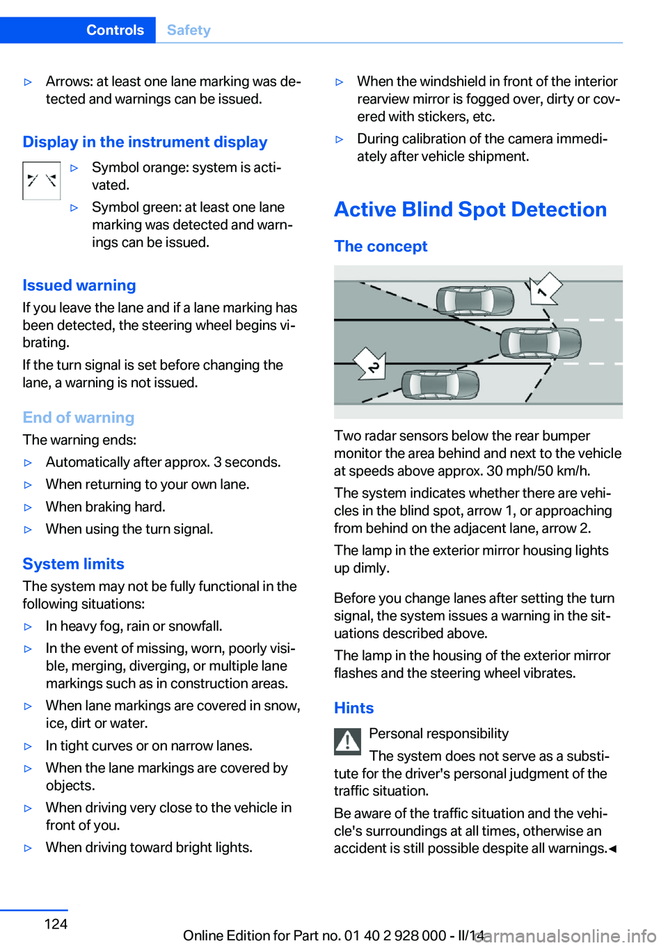
The concept
Two radar sensors below the rear bumper
monitor the area behind and next to the vehicle
at speeds above approx. 30 mph/50 km/h.
The system indicates whether there are vehi‐
cles in the blind spot, arrow 1, or approaching
from behind on the adjacent lane, arrow 2.
The lamp in the exterior mirror housing lights
up dimly.
Before you change lanes after setting the turn
signal, the system issues a warning in the sit‐
uations described above.
The lamp in the housing of the exterior mirror
flashes and the steering wheel vibrates.
Hints Personal responsibility
The system does not serve as a substi‐
tute for the driver's personal judgment of the
traffic situation.
Be aware of the traffic situation and the vehi‐
cle's surroundings at all times, otherwise an
accident is still possible despite all warnings.◀
Seite 124ControlsSafety124
Online Edition for Part no. 01 40 2 928 000 - II/14
Page 125 of 267

At a glance
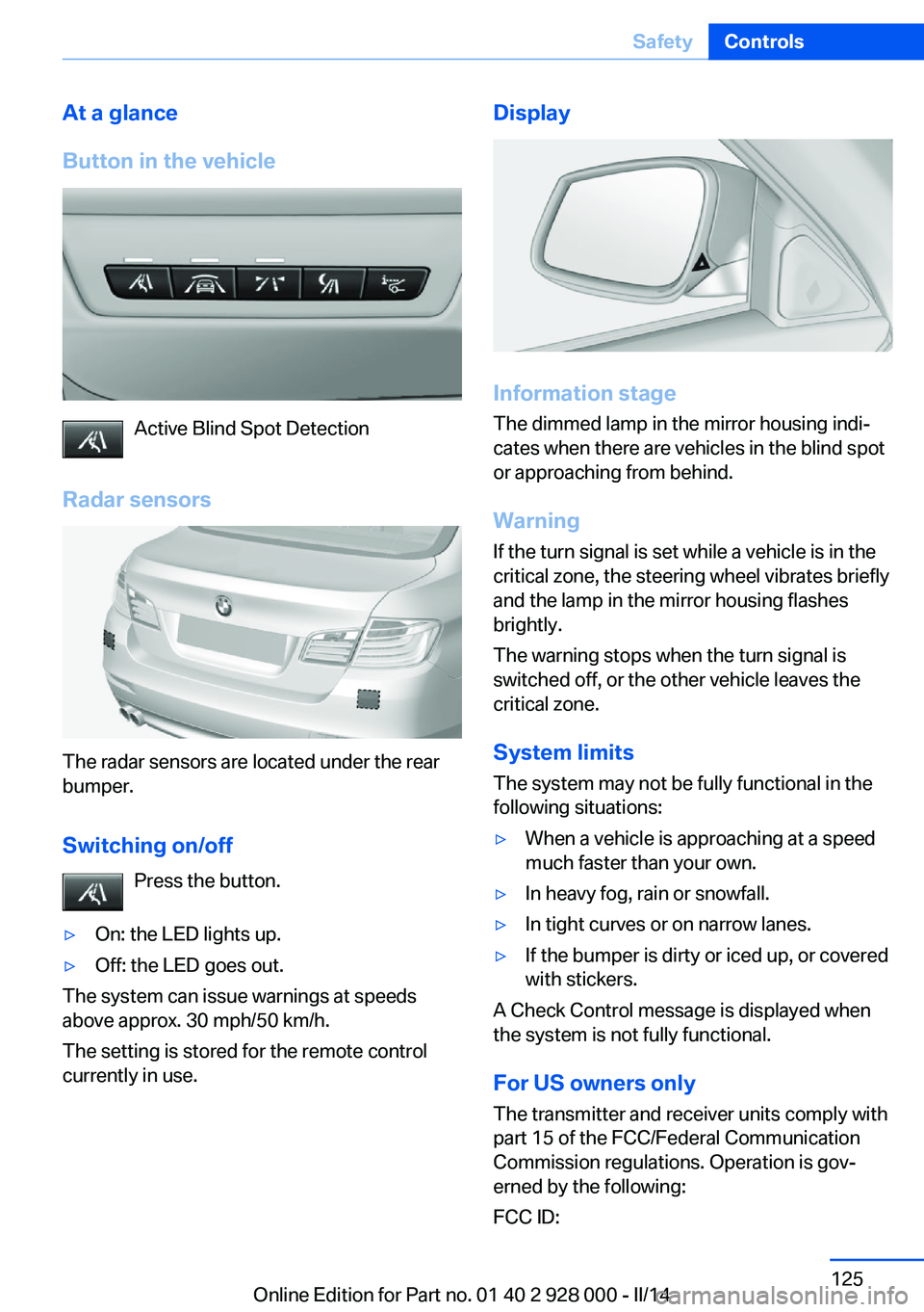
Button in the vehicle
Active Blind Spot Detection
Radar sensors
The radar sensors are located under the rear
bumper.
Switching on/off Press the button.
▷On: the LED lights up.▷Off: the LED goes out.
The system can issue warnings at speeds
above approx. 30 mph/50 km/h.
The setting is stored for the remote control
currently in use.
Display
Information stage
The dimmed lamp in the mirror housing indi‐
cates when there are vehicles in the blind spot
or approaching from behind.
Warning
If the turn signal is set while a vehicle is in the
critical zone, the steering wheel vibrates briefly
and the lamp in the mirror housing flashes
brightly.
The warning stops when the turn signal is
switched off, or the other vehicle leaves the
critical zone.
System limits
The system may not be fully functional in the
following situations:
▷When a vehicle is approaching at a speed
much faster than your own.▷In heavy fog, rain or snowfall.▷In tight curves or on narrow lanes.▷If the bumper is dirty or iced up, or covered
with stickers.
A Check Control message is displayed when
the system is not fully functional.
For US owners only The transmitter and receiver units comply with
part 15 of the FCC/Federal Communication
Commission regulations. Operation is gov‐
erned by the following:
FCC ID:
Seite 125SafetyControls125
Online Edition for Part no. 01 40 2 928 000 - II/14
Page 127 of 267

After a break, another recommendation to take
a break cannot be displayed until after approxi‐
mately 45 minutes.
System limits
The function may be limited in the following
situations, for instance, and will either output
an incorrect warning or no warning at all:▷When the clock is set incorrectly.▷When the vehicle speed is mainly below
about 43 mph/70 km/h.▷With a sporty driving style, such as during
rapid acceleration or when cornering
quickly.▷In active driving situations, such as when
changing lanes frequently.▷When the road surface is poor.▷In the event of strong side winds.
PreCrash
The concept With this system critical driving situations that
might result in an accident can be detected
above a speed of approx. 20 mph/30 km/h. In these situations, preventative protection
measures are automatically undertaken to
minimize the risk in the event of an accident as
much as possible.
Critical driving situations may include:
▷Full brake applications.▷Severe understeering.▷Severe oversteering.
If the vehicle includes the collision warning or
collision warning with braking feature, impend‐
ing collisions with vehicles driving ahead or
stopped in front of you can also be detected
within the system's range.
Note
Personal responsibility
The system cannot possibly serve as a
substitute for the driver's personal judgment of
the traffic situation. The system may not al‐
ways detect critical situations reliably and in a
timely manner. Adapt speed to traffic situation
and drive alertly; otherwise, a risk to safety may
result.◀
Function
After the safety belt is buckled, the front belts
are automatically pretensioned once after the
vehicle is driven is away.
In critical driving situations, the following indi‐
vidual functions become active as needed:▷The front belts are automatically preten‐
sioned.▷Automatic closing of the windows.▷Automatic closing of the glass sunroof.▷For vehicles equipped with Comfort Seats:
automatic positioning of the backrest for
the front passenger seat.
After a critical driving situation without an acci‐
dent, the front belts are loosened again. All
other systems can be restored to the desired
setting.
If the belt tension does not loosen automati‐
cally, stop the vehicle and unbuckle the belt
using the red button in the buckle. Fasten the
belt before continuing on your trip.
PostCrash
In the event of an accident, the system can
bring the car to a halt automatically without in‐
tervention by the driver in certain situations.
This can reduce the risk of a further collision
and the consequences thereof.
Depressing the brake pedal can cause the ve‐
hicle to brake harder. This interrupts automatic
braking. Depressing the accelerator pedal also
interrupts automatic braking.
Seite 127SafetyControls127
Online Edition for Part no. 01 40 2 928 000 - II/14
Page 130 of 267

speed and by applying brakes to the individual
wheels.
Adjust your driving style to the situation
An appropriate driving style is always the
responsibility of the driver.
The laws of physics cannot be repealed, even
with DSC.
Therefore, do not reduce the additional safety
margin by driving in a risky manner.◀
Indicator/warning lamps The indicator lamp flashes: DSC con‐
trols the drive forces and brake forces.
The indicator lamp lights up: DSC has
failed.
Deactivating DSC: DSC OFF
When DSC is deactivated, driving stability is
reduced during acceleration and when driving in bends.
Stabilizing interventions by the Integral Active
Steering system are only performed by the rear axle steering.
To increase vehicle stability, activate DSC
again as soon as possible.
Deactivating DSC Press and hold the button, but not lon‐
ger than approx. 10 seconds, until the
indicator lamp for DSC OFF lights up in the in‐
strument cluster and DSC OFF is displayed.
The DSC system is switched off.
Steering and, depending on the equipment,
the chassis are adjusted for sporty driving.
Activating DSC Press the button.
DSC OFF and the DSC OFF indicator
lamp go out.Indicator/warning lamps
When DSC is deactivated, DSC OFF is dis‐
played in the instrument cluster.
The indicator lamp lights up: DSC is
deactivated.
DTC Dynamic Traction
Control
The concept The DTC system is a version of the DSC in
which forward momentum is optimized.
The system ensures maximum forward mo‐
mentum on special road conditions, e.g., unp‐
lowed snowy roads, but driving stability is lim‐
ited.
It is therefore necessary to drive with appropri‐
ate caution.
You may find it useful to briefly activate DTC
under the following special circumstances:▷When driving in slush or on uncleared,
snow-covered roads.▷When rocking the vehicle or driving off in
deep snow or on loose surfaces.▷When driving with snow chains.
Deactivating/activating DTC Dynamic
Traction Control
Activating the Dynamic Traction Control DTC
provides maximum traction on loose ground.
Driving stability is limited during acceleration
and when driving in bends.
Activating DTC Press the button.
TRACTION is displayed in the instru‐
ment cluster and the indicator lamp for DSC
OFF lights up.
Seite 130ControlsDriving stability control systems130
Online Edition for Part no. 01 40 2 928 000 - II/14
Page 131 of 267

Deactivating DTCPress the button again.
TRACTION and the DSC OFF indica‐
tor lamp go out.
Indicator/warning lamps When DTC is activated, TRACTION is dis‐
played in the tachometer.
The indicator lamp lights up: DTC Dy‐
namic Traction Control is activated.
xDrive
xDrive is the all-wheel-drive system of your ve‐
hicle. Concerted action by the xDrive and DSC
further optimize traction and driving dynamics.
The xDrive all-wheel-drive system variably dis‐
tributes the drive forces to the front and rear
axles as demanded by the driving situation and
road surface.
HDC Hill Descent Control
The concept HDC is a downhill driving assistant that auto‐
matically controls vehicle speed on steep
downhill gradients. Without applying the
brakes, the vehicle moves at slightly more than
walking speed.
Hill Descent Control can be activated at
speeds below approx. 22 mph/35 km/h. When
driving downhill, the vehicle reduces its speed
to approx. walking speed and then keeps its
speed constant.
As long as there is active braking, the system
is on standby. The system does not brake the
vehicle during this time.
Only use HDC in low gears or in selector lever
position D or R.Increasing or decreasing vehicle
speed
Specify desired speed in the range from ap‐
prox. 4 mph/6 km/h to approx. 15 mph/25 km/h
using the rocker switch of the cruise control on
the steering wheel. Vehicle speed can be
changed by lightly accelerating.▷Press up the rocker switch to the point of
resistance: the speed increases gradually.▷Press up the rocker switch past the point
of resistance: the speed increases while
the rocker switch is pressed.▷Press down the rocker switch to the point
of resistance: the speed decreases gradu‐
ally.▷Press down the rocker switch past the
point of resistance: when driving forward,
the speed decreases to approx.
6 mph/10 km/h; when reversing, the speed
decreases to approx. 4 mph/6 km/h.
Activating HDC
Press the button; the LED above the but‐
ton lights up.
Seite 131Driving stability control systemsControls131
Online Edition for Part no. 01 40 2 928 000 - II/14
Page 133 of 267

Integral Active SteeringThe concept
Integral Active Steering is a combination of Ac‐
tive Steering and rear axle steering.
Active Steering varies the steering angle of the
wheels in relation to the steering wheel move‐
ment as a function of the speed.
At speeds up to approx. 37 mph/60 km/h, e.g.,
in curves, the steering angle is increased, i.e.,
steering becomes more direct.
The rear axle steering acts to increase maneu‐
verability by turning the rear wheels slightly in
a direction opposite to the front wheels.
At higher speeds, the steering angle is increas‐
ingly reduced.
The rear wheels are turned to the same angle
as the front wheels.
In critical situations, Integral Active Steering
can specifically steer the front and rear wheels
to stabilize the vehicle before the driver inter‐
venes, e.g., when braking where road condi‐
tions differ on the left and right sides of the ve‐
hicle.
InitializingIn rare cases, it may become necessary to initi‐
alize the Integral Active Steering.
The warning lamp lights up. A Check
Control message is displayed.1.With the engine running, turn the steering
wheel all the way to the left and right sev‐
eral times in a uniform manner until the
warning lamp disappears.2.Have the system checked if the warning
lamp does not go out after moving the
steering wheel approx. 6 times or if the
steering wheel is at an angle.Using snow chains
Note When snow chains are in use, refer to
page 223, rear wheel steering is deactivated.
Programs The system offers several different programs.
The programs can be selected via the Driving
Dynamics Control, refer to page 133.
SPORT
Consistently sporty tuning of the Integral Ac‐
tive Steering for greater driving agility.
COMFORT Balanced tuning of the Integral Active Steering
for optimal traveling comfort.
Malfunction
In the event of a malfunction, the steering
wheel must be turned further, while the vehicle
responds more sensitively to steering wheel
movements in the higher speed range.
The stability-enhancing intervention may be
deactivated.
Proceed cautiously and drive defensively.
Have the system checked.
Driving Dynamics Control The conceptThe Driving Dynamics Control can be used to
adjust the driving dynamics of the vehicle. For
this purpose various programs are available for
selection that are activated via the two buttons
of the Driving Dynamics Control and the DSC
OFF-button.Seite 133Driving stability control systemsControls133
Online Edition for Part no. 01 40 2 928 000 - II/14