2014 BMW 528I XDRIVE turn signal
[x] Cancel search: turn signalPage 101 of 267

▷High beams off/headlamp flasher, arrow 2.
The High-beam Assistant can be switched off
when manually adjusting the light. To reacti‐
vate the High-beam Assistant, press the but‐
ton on the turn signal lever.
System limits Personal responsibility
The high-beam assistant cannot serve as
a substitute for the driver's personal judgment
of when to use the high beams. Therefore,
manually switch off the high beams in situa‐
tions where this is required to avoid a safety
risk.◀
The system is not fully functional in situations
such as the following, and driver intervention
may be necessary:
▷In very unfavorable weather conditions,
such as fog or heavy precipitation.▷In detecting poorly-lit road users, such as
pedestrians, cyclists, horseback riders and
wagons; when driving close to train or ship
traffic; and at animal crossings.▷In tight curves, on hilltops or in depres‐
sions, in cross traffic or half-obscured on‐
coming traffic on freeways.▷In poorly-lit towns and cities and in the
presence of highly reflective signs.▷At low speeds.▷When the windshield behind the interior
rearview mirror is fogged over, dirty or cov‐
ered with stickers, etc.Camera
The camera is located near the base of the
mirror.
Keep the windshield in the area behind the in‐
terior rear view mirror clean and clear.
Fog lamps
Front fog lamps The parking lamps or low beams must be
switched on.
Press the button. The green indicator
lamp lights up.
If the automatic headlamp control, refer to
page 99, is activated, the low beams will come
on automatically when you switch on the front
fog lamps.
When the high beams or headlamp flasher are
activated, the front fog lamps are not switched
on.
Instrument lighting Adjusting The parking lamps or low beams
must be switched on to adjust
the brightness.
Adjust the brightness using the
thumbwheel.
Seite 101LampsControls101
Online Edition for Part no. 01 40 2 928 000 - II/14
Page 123 of 267

Limited detection:▷People or animals who are fully or partially
covered, especially when their heads are
covered.▷People who are not in an upright position,
e.g., lying down.▷Cyclists on unconventional bicycles (e.g.,
recumbent bicycles).▷After physical damage to the system, e.g.,
after an accident.
No display on the rear screen
The image from Night Vision cannot be dis‐
played on the rear screen.
Lane departure warning The concept Starting at a specific speed, this system alerts
you when the vehicle on streets with lane
markings is about to leave the lane. This
speed, depending on the country version, is
between 35 mph/55 km/h and
45 mph/70 km/h.
When switching on the system below this
speed, a message is displayed in the instru‐
ment cluster.
The steering wheel begins vibrating gently in
the event of warnings. The time of the warning
may vary depending on the current driving sit‐
uation.
The system does not provide a warning if the
turn signal is set before leaving the lane.
Hints Personal responsibility
The system cannot serve as a substitute
for the driver's personal judgment of the
course of the road and the traffic situation.
In the event of a warning, do not jerk the steer‐
ing wheel, as you may lose control of the vehi‐
cle.◀
At a glance
Button in the vehicle
Lane departure warning
Camera
The camera is located near the base of the
mirror.
Keep the windshield in the area behind the in‐
terior rear view mirror clean and clear.
Switching on/off Press the button.
▷On: the LED lights up.▷Off: the LED goes out.
The setting is stored for the remote control
currently in use.
Display in the instrument cluster
▷Lines: system is activated.Seite 123SafetyControls123
Online Edition for Part no. 01 40 2 928 000 - II/14
Page 124 of 267

▷Arrows: at least one lane marking was de‐
tected and warnings can be issued.
Display in the instrument display
▷Symbol orange: system is acti‐
vated.▷Symbol green: at least one lane
marking was detected and warn‐
ings can be issued.
Issued warning
If you leave the lane and if a lane marking has
been detected, the steering wheel begins vi‐
brating.
If the turn signal is set before changing the
lane, a warning is not issued.
End of warning
The warning ends:
▷Automatically after approx. 3 seconds.▷When returning to your own lane.▷When braking hard.▷When using the turn signal.
System limits
The system may not be fully functional in the
following situations:
▷In heavy fog, rain or snowfall.▷In the event of missing, worn, poorly visi‐
ble, merging, diverging, or multiple lane
markings such as in construction areas.▷When lane markings are covered in snow,
ice, dirt or water.▷In tight curves or on narrow lanes.▷When the lane markings are covered by
objects.▷When driving very close to the vehicle in
front of you.▷When driving toward bright lights.▷When the windshield in front of the interior
rearview mirror is fogged over, dirty or cov‐
ered with stickers, etc.▷During calibration of the camera immedi‐
ately after vehicle shipment.
Active Blind Spot Detection
The concept
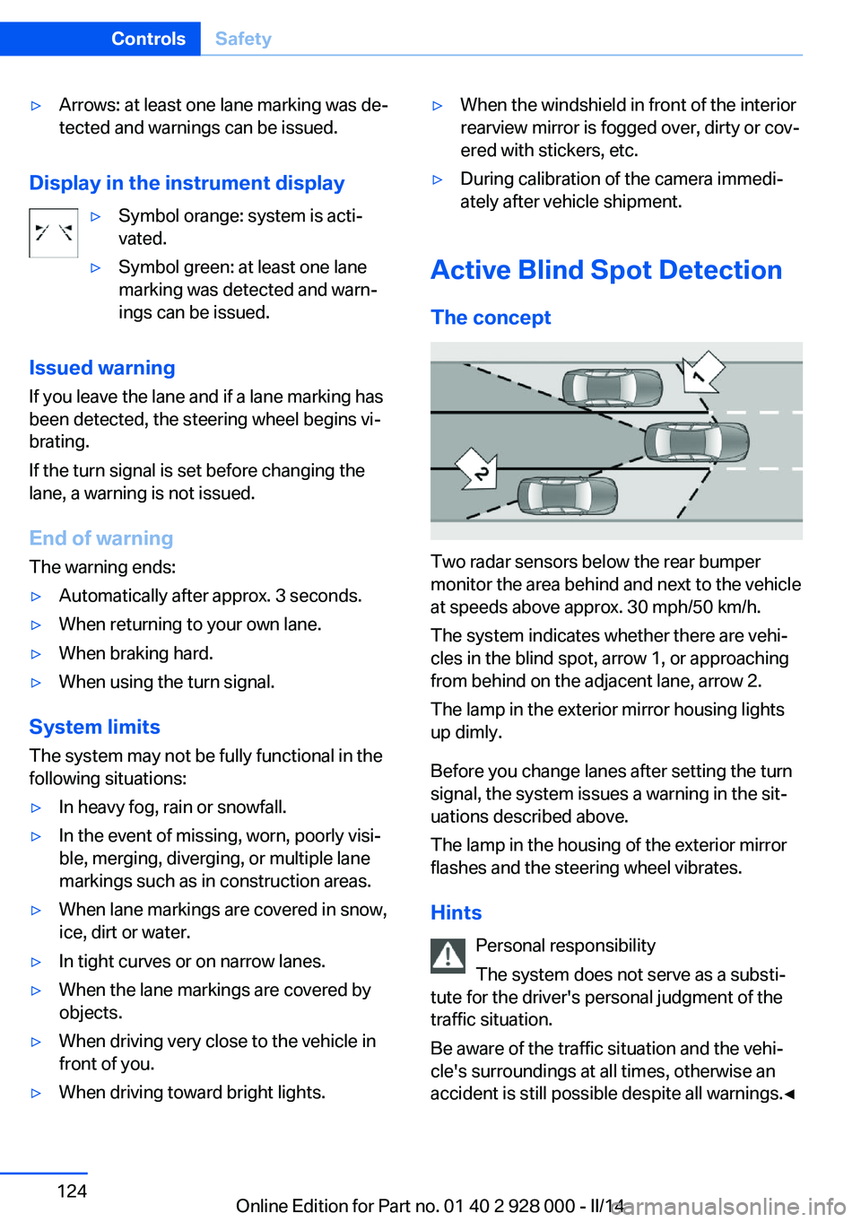
Two radar sensors below the rear bumper
monitor the area behind and next to the vehicle
at speeds above approx. 30 mph/50 km/h.
The system indicates whether there are vehi‐
cles in the blind spot, arrow 1, or approaching
from behind on the adjacent lane, arrow 2.
The lamp in the exterior mirror housing lights
up dimly.
Before you change lanes after setting the turn
signal, the system issues a warning in the sit‐
uations described above.
The lamp in the housing of the exterior mirror
flashes and the steering wheel vibrates.
Hints Personal responsibility
The system does not serve as a substi‐
tute for the driver's personal judgment of the
traffic situation.
Be aware of the traffic situation and the vehi‐
cle's surroundings at all times, otherwise an
accident is still possible despite all warnings.◀
Seite 124ControlsSafety124
Online Edition for Part no. 01 40 2 928 000 - II/14
Page 125 of 267

At a glance
Button in the vehicle
Active Blind Spot Detection
Radar sensors
The radar sensors are located under the rear
bumper.
Switching on/off Press the button.
▷On: the LED lights up.▷Off: the LED goes out.
The system can issue warnings at speeds
above approx. 30 mph/50 km/h.
The setting is stored for the remote control
currently in use.
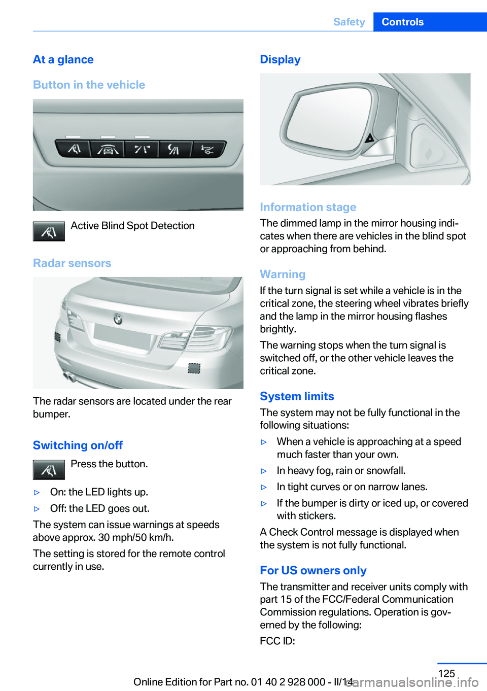
Display
Information stage
The dimmed lamp in the mirror housing indi‐
cates when there are vehicles in the blind spot
or approaching from behind.
Warning
If the turn signal is set while a vehicle is in the
critical zone, the steering wheel vibrates briefly
and the lamp in the mirror housing flashes
brightly.
The warning stops when the turn signal is
switched off, or the other vehicle leaves the
critical zone.
System limits
The system may not be fully functional in the
following situations:
▷When a vehicle is approaching at a speed
much faster than your own.▷In heavy fog, rain or snowfall.▷In tight curves or on narrow lanes.▷If the bumper is dirty or iced up, or covered
with stickers.
A Check Control message is displayed when
the system is not fully functional.
For US owners only The transmitter and receiver units comply with
part 15 of the FCC/Federal Communication
Commission regulations. Operation is gov‐
erned by the following:
FCC ID:
Seite 125SafetyControls125
Online Edition for Part no. 01 40 2 928 000 - II/14
Page 145 of 267

Switching offDeactivated or interrupted system
If the system is deactivated or inter‐
rupted, actively intervene by braking, steering
and, if necessary, with evasive maneuvers; oth‐
erwise, there is the danger of an accident oc‐
curring.◀
Press the button.
The indicator goes out. Stored desired speed
and distance are still kept by the ACC.
The system does not carry out a steering
movement.
Interrupting When active, press the button.
The system is automatically interrupted in the
following situations:▷At a speed above 25 mph/40 km/h.▷With only one detected lane marking.▷When you leave the limited access high‐
way.▷When the steering wheel is released.▷When you intervene in the steering.▷When you leave your own lane.▷When there is no vehicle ahead.▷When the turn signal is on.▷When the lane is too narrow.
Rolling bars:
Congestion assistant is no longer ac‐
celerating. To accelerate further, acti‐
vate ACC by briefly pressing the accelerator,
pressing the RES button or rocker switch.
Red flashing and signal tone:
Congestion Assistant is interrupted.
The system does not carry out a steer‐
ing movement. ACC exercises control.
If the system conditions are met, the system
reactivates automatically.
When you leave the approved road type, the
system is first interrupted and then shuts
down.
Distance Selecting a distance
Adjust the distance according to the traf‐
fic and weather conditions; otherwise, there is
the danger of an accident occurring. Maintain
the prescribed safety distance.◀
Adjust distance Press the button repeatedly until the
desired distance is set.
Distance to vehicle ahead of you
The selected distance to the vehicle driving
ahead of you is shown.Distance displayDistance 1Distance 2Distance 3Distance 4
This value is set after the system is
switched on.
Selecting a distance
Adjust the distance according to the traf‐
fic and weather conditions; otherwise, there is
the danger of an accident occurring. Maintain
the prescribed safety distance.◀
Seite 145Driving comfortControls145
Online Edition for Part no. 01 40 2 928 000 - II/14
Page 158 of 267

Suitable parking space▷Gap between two objects with a minimum
length of approx. 5 ft/1.5 m.▷Min. length of gap between two objects:
your vehicle's length plus approx.
4 ft/1.2 m.▷Minimum depth: approx. 5 ft/1.5 m.
For parking procedure
▷Doors and trunk lid closed.▷Parking brake released.▷When parking in parking spaces on the
driver's side, the corresponding turn signal
must be set where applicable.
Automatic transmission:
▷Driver's seat belt fastened.
At a glance
Button in the vehicle
Parking assistant
Ultrasound sensors
The ultrasound sensors used to measure park‐
ing spaces are located in the side turn signals.
To ensure full operability:
▷Keep the sensors clean and free of ice.▷When using high-pressure washers, do not
spray the sensors for long periods and
maintain a distance of at least 12 in/30 cm.▷Do not paste over sensors.
Switching on/off
Switching on with the button Press the button.
The LED lights up.
The current status of the parking space search
is indicated on the Control Display.
Parking assistant is activated automatically.
Switching on with the reverse gear
Shift into reverse.
The current status of the parking space search
is indicated on the Control Display.
To activate:
"Parking Assistant"
Switching off The system can be deactivated as follows:
▷Press the button.▷Switch off the ignition.Seite 158ControlsDriving comfort158
Online Edition for Part no. 01 40 2 928 000 - II/14
Page 234 of 267

the service center if you are unfamiliar with
them or they are not described here.
You can obtain a selection of replacement
bulbs at the service center.
Danger of burns
Only change bulbs when they are cool;
otherwise, there is the danger of getting
burned.◀
Working on the lighting system
When working on the lighting system,
you should always switch off the lights af‐
fected to prevent short circuits.
To avoid possible injury or equipment damage
when replacing bulbs, observe any instructions
provided by the bulb manufacturer.◀
Do not perform work/bulb replacement
on xenon headlamps
Have any work on the xenon lighting system,
including bulb replacement, performed only by
a service center. Due to the high voltage
present in the system, there is the danger of
fatal injuries if work is carried out improperly.◀
Do not touch the bulbs
Do not touch the glass of new bulbs with
your bare hands, as even minute amounts of
contamination will burn into the bulb's surface
and reduce its service life.
Use a clean tissue, cloth or something similar,
or hold the bulb by its base.◀
Light-emitting diodes (LEDs)
Some items of equipment use light-emitting
diodes installed behind a cover as a light
source.
These light-emitting diodes, which are related
to conventional lasers, are officially designated as Class 1 light-emitting diodes.Do not remove the covers
Do not remove the covers, and never
stare into the unfiltered light for several hours;
otherwise, irritation of the retina could result.◀
Headlamp glass
Condensation can form on the inside of the ex‐
ternal lamps in cool or humid weather. When
driving with the light switched on, the conden‐
sation evaporates after a short time. The head‐
lamp glasses do not need to be changed.
If the headlamps do not dim despite driving
with the light switched on, increasing humidity
forms, e. g. water droplets in the light, have the
service center check this.
Headlamp setting
The headlamp adjustments can be affected by
changing lamps and bulbs. Therefore after a
change, have the headlamp setting checked
and corrected by Service.
Front lamps, bulb replacement
Xenon headlamps
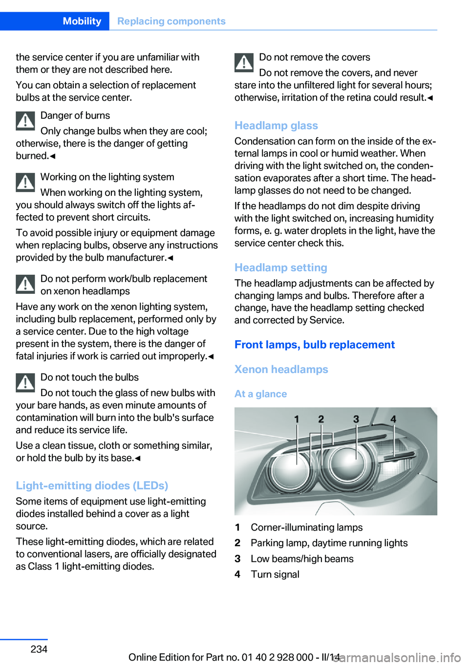
At a glance1Corner-illuminating lamps2Parking lamp, daytime running lights3Low beams/high beams4Turn signalSeite 234MobilityReplacing components234
Online Edition for Part no. 01 40 2 928 000 - II/14
Page 235 of 267

Hints
Because of the long life of these bulbs, the
likelihood of failure is very low. Switching the
lamps on and off frequently shortens their life.
If a bulb fails, switch on the front fog lamps and
continue the trip with great care. Comply with
local regulations.
Do not perform work/bulb replacement
on xenon headlamps
Have any work on the xenon lighting system,
including bulb replacement, performed only by
a service center. Due to the high voltage
present in the system, there is the danger of
fatal injuries if work is carried out improperly.◀
For checking and adjusting headlamp aim,
please contact your BMW center.
Parking lamps and roadside parking lamps,
turn signal lamp
Follow general instructions, refer to page 233.
These lights feature LED technology.
Contact your service center in the event of a
malfunction.
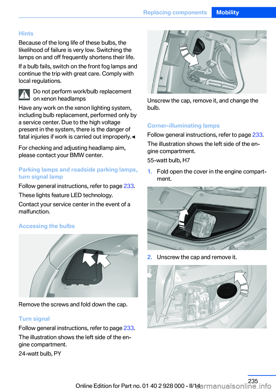
Accessing the bulbs
Remove the screws and fold down the cap.
Turn signal
Follow general instructions, refer to page 233.
The illustration shows the left side of the en‐
gine compartment.
24-watt bulb, PY
Unscrew the cap, remove it, and change the
bulb.
Corner-illuminating lamps
Follow general instructions, refer to page 233.
The illustration shows the left side of the en‐
gine compartment.
55-watt bulb, H7
1.Fold open the cover in the engine compart‐
ment.2.Unscrew the cap and remove it.Seite 235Replacing componentsMobility235
Online Edition for Part no. 01 40 2 928 000 - II/14