2014 BMW 5 SERIES Load cover
[x] Cancel search: Load coverPage 71 of 273

Mounts for the lower LATCH anchorsThe lower anchors may be used to attach the
CRS to the vehicle seat up to a combined child
and CRS weight of 65 lb/30 kg when the child
is restrained by the internal harnesses.
Properly engage the lower LATCH an‐
chors
Make sure that the lower LATCH anchors have
properly engaged and that the child restraint
system is resting snugly against the backrest;
otherwise, the degree of protection may be re‐
duced.◀
Before mounting the LATCH child restraint
system, pull the belt away from the child re‐
straint system.
The corresponding symbol shows the
mounts for the lower LATCH anchors.
Without a through-loading system:
Position
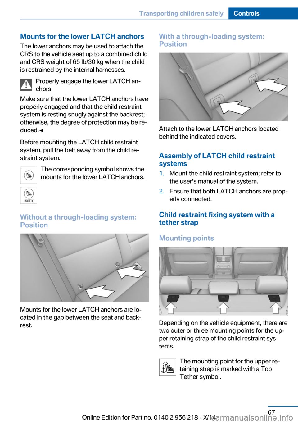
Mounts for the lower LATCH anchors are lo‐
cated in the gap between the seat and back‐
rest.
With a through-loading system:
Position
Attach to the lower LATCH anchors located
behind the indicated covers.
Assembly of LATCH child restraint
systems
1.Mount the child restraint system; refer to
the user's manual of the system.2.Ensure that both LATCH anchors are prop‐
erly connected.
Child restraint fixing system with a
tether strap
Mounting points
Depending on the vehicle equipment, there are
two outer or three mounting points for the up‐
per retaining strap of the child restraint sys‐
tems.
The mounting point for the upper re‐
taining strap is marked with a Top
Tether symbol.
Seite 67Transporting children safelyControls67
Online Edition for Part no. 0140 2 956 218 - X/14
Page 140 of 273

Therefore, do not reduce the additional safety
margin by driving in a risky manner.◀
Do not deactivate DSC when driving withroof load
Do not deactivate Dynamic Stability Control
DSC when driving with roof load, e.g. roof-
mounted luggage rack.
Otherwise, driving safety is not given in driv‐
ing-critical situation due to the elevated center
of gravity.◀
At a glance
Button in the vehicle
DSC OFF button
Indicator/warning lights The indicator lamp flashes: DSC con‐
trols the drive and braking forces.
The indicator lamp lights up: DSC has
failed.
Deactivating DSC: DSC OFF
When DSC is deactivated, driving stability is
reduced during acceleration and when driving
in curves.
Stabilizing interventions by the Integral Active
Steering system are only performed by the
rear axle steering.
To increase vehicle stability, activate DSC
again as soon as possible.
Deactivating DSC
Press and hold this button but not lon‐
ger than approx. 10 seconds, until the
indicator lamp for DSC OFF lights up in the in‐
strument cluster and displays DSC OFF.
The DSC system is switched off.
The steering and, depending on the equip‐
ment, suspension are tuned for sporty driving.
Activating DSC Press button.
DSC OFF and the DSC OFF indicator
lamp go out.
Indicator/warning lights
When DSC is deactivated, DSC OFF is dis‐
played in the instrument cluster.
The indicator lamp lights up: DSC is
deactivated.
DTC Dynamic Traction
Control
The concept The DTC system is a version of the DSC where
forward momentum is optimized.
The system ensures maximum headway on
special road conditions or loose road surfaces,
e.g., unplowed snowy roads, but with some‐
what limited driving stability.
Activating the Dynamic Traction Control DTC
provides maximum traction. Driving stability is
limited during acceleration and when driving in
curves.
Therefore drive with appropriate caution.
You may find it useful to briefly activate DTC
under the following special circumstances:▷When driving in slush or on uncleared,
snow-covered roads.Seite 136ControlsDriving stability control systems136
Online Edition for Part no. 0140 2 956 218 - X/14
Page 180 of 273

The lighter can be removed as soon as it pops
back out.
Danger of burns
Only hold the hot lighter by its knob; oth‐
erwise, there is a danger of getting burned.
Take the remote control with you when leaving
the vehicle so that children cannot use the
lighter and burn themselves.◀
Replace the cover after use
Reinsert the lighter or socket cover after
use, otherwise objects may get into the lighter
socket or fixture and cause a short circuit.◀
Connecting electrical
devices
Hints Do not connect charging devices to the
12 volt socket in the vehicle
Do not connect battery chargers to the fac‐
tory-installed 12 volt sockets in the vehicle as
this may damage the vehicle battery due to an
increased power consumption.◀
Replace the cover after use
Reinsert the lighter or socket cover after
use, otherwise objects may get into the lighter
socket or fixture and cause a short circuit.◀
Sockets
General information
The lighter socket can be used as a socket for
electrical equipment while the engine is run‐
ning or when the ignition is switched on.
Note The total load of all sockets must not exceed
140 watts at 12 volts.Do not damage the socket by using unsuitable
connectors.
Front center console: manual
transmission
Press on the cover.
Remove the cover or cigarette lighter.
Front center console: Steptronic
transmission
Press on the cover.
Remove the cover or cigarette lighter.
Center armrest
Remove the cover.
Seite 176ControlsInterior equipment176
Online Edition for Part no. 0140 2 956 218 - X/14
Page 181 of 273

Rear center console
Remove the cover or cigarette lighter.
In the front passenger footwell
Socket is located below the glove compart‐
ment.
To access the socket: fold open the cover.
In the cargo area The socket is located in the cover of the load‐
ing lip.
To access the socket: fold open the cover.
USB interface for data
transfer
The concept Connection for importing and exporting data
on USB devices, e.g.:
▷Personal Profile settings, refer to page 35.▷Music collection, see user's manual for
Navigation, Entertainment and Communi‐
cation.Hints
Observe the following when connecting:▷Do not use force when plugging the con‐
nector into the USB interface.▷Do not connect devices such as fans or
lights to the USB interface.▷Do not connect USB hard drives.▷Do not use the USB interface for recharg‐
ing external devices.
With navigation system Professional
or TV: at a glance
The USB interface is located in the center arm‐
rest.
Through-loading system The concept The cargo area can be enlarged by folding
down the rear seat backrest.
The rear seat backrest is divided into two parts at a ratio of 60 to 40.
The sides can be folded down separately or to‐
gether.
Hints Danger of jamming
Before folding down the rear seat back‐
rests, ensure that the area of movement of the
backrests is clear. In particular, ensure that no
one is located in or reaches into the area of
movement of the rear seat backrests when the
Seite 177Interior equipmentControls177
Online Edition for Part no. 0140 2 956 218 - X/14
Page 183 of 273

Ski bag
Capacity The ski bag can be used to transport up to four
pairs of skis with a length of up to 6 ft/2.10 m
or, depending on the binding, up to two snow‐
boards with a length of up to 5 ft/1.60 m.
Preparing and loading the ski bag1.Fold open the center armrest on the inside.2.Open the inside cover and cargo area by
pressing the button.3.Lay out the ski bag.4.Load the ski bag. If necessary, wrap the
sharp edges of the skis.5.Insert the tongue plate into the belt buckle.6.Tighten the retaining strap.
Securing the ski bag
Secure the ski bag by tightening the re‐
taining strap; otherwise, the contents could
present a source of danger to the passengers,
for example during braking or evasive maneu‐
vers.◀
Removing the ski bag The ski bag can be removed entirely, e.g., to
dry quickly or to use other inserts.
1.Pull the handle forward and lift the ski bag
out.2.Close the cover in the cargo area.Seite 179Interior equipmentControls179
Online Edition for Part no. 0140 2 956 218 - X/14
Page 197 of 273

Load
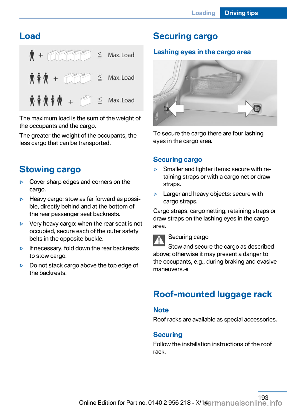
The maximum load is the sum of the weight of
the occupants and the cargo.
The greater the weight of the occupants, the
less cargo that can be transported.
Stowing cargo
▷Cover sharp edges and corners on the
cargo.▷Heavy cargo: stow as far forward as possi‐
ble, directly behind and at the bottom of
the rear passenger seat backrests.▷Very heavy cargo: when the rear seat is not
occupied, secure each of the outer safety
belts in the opposite buckle.▷If necessary, fold down the rear backrests
to stow cargo.▷Do not stack cargo above the top edge of
the backrests.Securing cargo
Lashing eyes in the cargo area
To secure the cargo there are four lashing
eyes in the cargo area.
Securing cargo
▷Smaller and lighter items: secure with re‐
taining straps or with a cargo net or draw
straps.▷Larger and heavy objects: secure with
cargo straps.
Cargo straps, cargo netting, retaining straps or
draw straps on the lashing eyes in the cargo
area.
Securing cargo
Stow and secure the cargo as described
above; otherwise it may present a danger to
the occupants, e.g., during braking and evasive
maneuvers.◀
Roof-mounted luggage rack Note
Roof racks are available as special accessories.
Securing
Follow the installation instructions of the roof
rack.
Seite 193LoadingDriving tips193
Online Edition for Part no. 0140 2 956 218 - X/14
Page 198 of 273

Roof drip rail with flaps
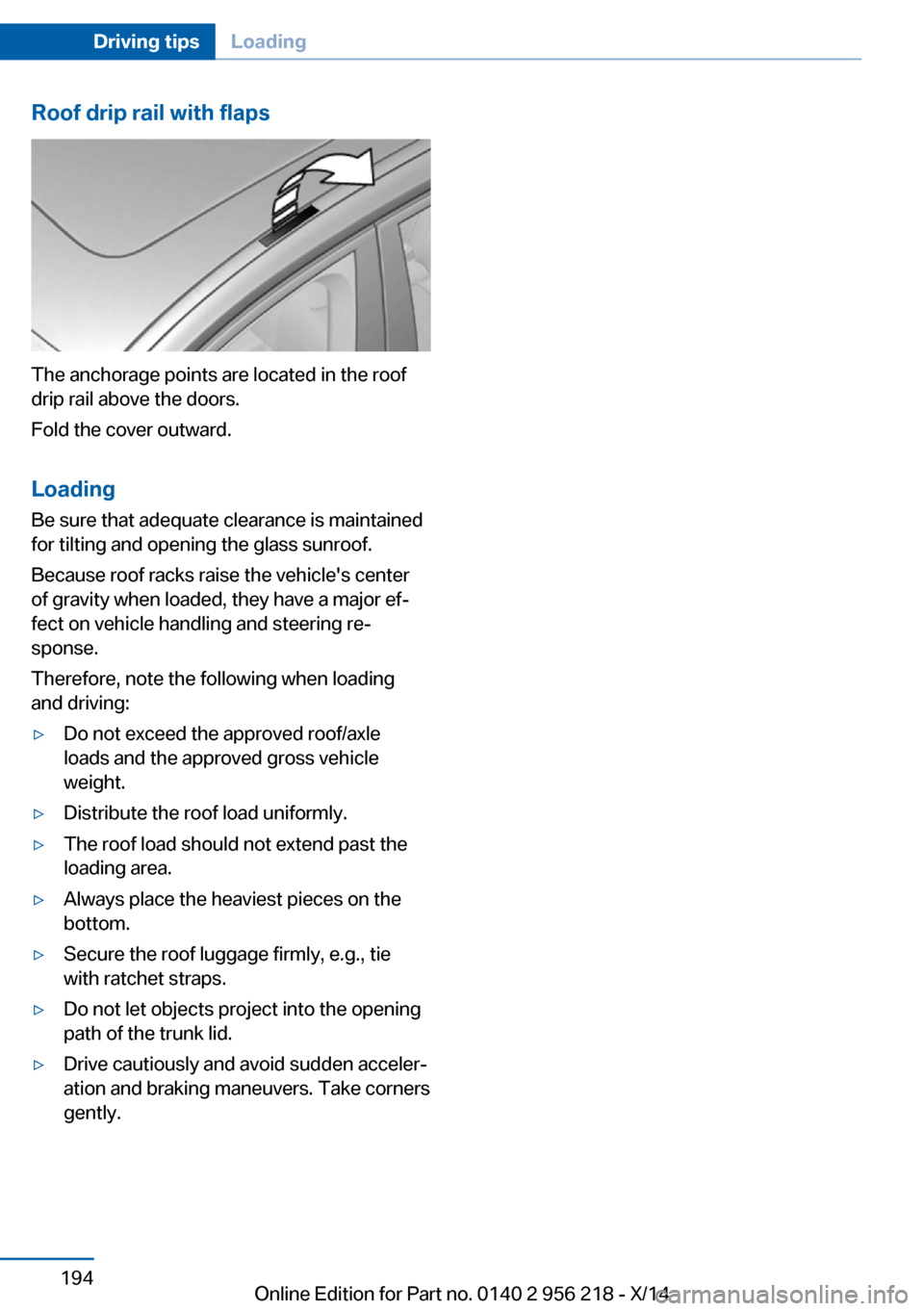
The anchorage points are located in the roof
drip rail above the doors.
Fold the cover outward.
Loading Be sure that adequate clearance is maintained
for tilting and opening the glass sunroof.
Because roof racks raise the vehicle's center
of gravity when loaded, they have a major ef‐
fect on vehicle handling and steering re‐
sponse.
Therefore, note the following when loading
and driving:
▷Do not exceed the approved roof/axle
loads and the approved gross vehicle
weight.▷Distribute the roof load uniformly.▷The roof load should not extend past the
loading area.▷Always place the heaviest pieces on the
bottom.▷Secure the roof luggage firmly, e.g., tie
with ratchet straps.▷Do not let objects project into the opening
path of the trunk lid.▷Drive cautiously and avoid sudden acceler‐
ation and braking maneuvers. Take corners
gently.Seite 194Driving tipsLoading194
Online Edition for Part no. 0140 2 956 218 - X/14
Page 245 of 273

Disposing of old batteriesHave old batteries disposed of by your
service center or bring them to a recy‐
cling center.
Maintain the battery in an upright position for
transport and storage. Secure the battery so
that it does not tip over during transport.
Fuses Hints Replacing fuses
Never attempt to repair a blown fuse and
do not replace a defective fuse with a substi‐
tute of another color or amperage rating; this
could lead to a circuit overload, ultimately re‐
sulting in a fire in the vehicle.◀
Plastic tweezers and information on the fuse
types and locations are stored in the fuse box
in the cargo area.
In the glove compartment
Push the handle up, arrow 1, and open the lid,
arrow 2.
In the cargo area
Open the cover on the right side trim, arrow.
Information on the fuse types and locations is
found on a separate sheet.
Seite 241Replacing componentsMobility241
Online Edition for Part no. 0140 2 956 218 - X/14