2014 BMW 5 SERIES GRAN TURISMO unlock
[x] Cancel search: unlockPage 53 of 259

The indicator lamp lights up for approx. 2 sec‐
onds and then continues to flash.
The tilt alarm sensor and interior motion sen‐
sor are turned off, until the vehicle is locked
again.
Switching off the alarm▷Unlock vehicle with the remote control or
reel on the ignition, if needed through
emergency detection of remote control, re‐
fer to page 35.▷With Comfort Access: If you are carrying
the remote control on your person, grasp
the driver side or front passenger side door
handle completely.
Power windows
General information Take the remote control with you
Take the remote control with you when
leaving the vehicle so that children, e.g., can‐
not operate the power windows and injure
themselves.◀
Opening
▷ Press the button to the resistance
point.
The window opens while the reel is held.▷ Press the reel beyond the resistance
point.The window opens automatically. Pressing
the reel again stops the motion.
See also: Convenient opening, refer to
page 37, via remote control.
Closing Keep the closing path clear
Monitor closing and make sure that the
closing path of the window is clear; otherwise,
injuries may result.◀
▷ Pull the reel to the resistance point.
The window closes while the reel is held.▷ Pull the reel beyond the resistance
point.
The window closes automatically. Pulling
again stops the motion.
See also: closing by means of Comfort Access,
refer to page 44.
Pinch protection system Danger of jamming even with pinch pro‐
tection
Even with the pinch protection system, check
that the window's closing path is clear; other‐
wise, the closing action may not stop in certain
situations, e.g., if thin objects are present.◀
No window accessories
Do not install any accessories in the win‐
dow's range of movement; otherwise, the
pinch protection system will be impaired.◀
If closing force exceeds a specific margin as a
window closes, closing is interrupted.
The window reopens slightly.
Seite 49Opening and closingControls49
Online Edition for Part no. 01 40 2 956 191 - X/14
Page 58 of 259
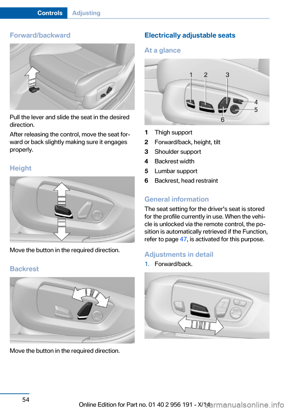
Forward/backward
Pull the lever and slide the seat in the desired
direction.
After releasing the control, move the seat for‐
ward or back slightly making sure it engages
properly.
Height
Move the button in the required direction. Backrest
Move the button in the required direction.
Electrically adjustable seats
At a glance1Thigh support2Forward/back, height, tilt3Shoulder support4Backrest width5Lumbar support6Backrest, head restraint
General information
The seat setting for the driver's seat is stored
for the profile currently in use. When the vehi‐
cle is unlocked via the remote control, the po‐
sition is automatically retrieved if the Function,
refer to page 47, is activated for this purpose.
Adjustments in detail
1.Forward/back.Seite 54ControlsAdjusting54
Online Edition for Part no. 01 40 2 956 191 - X/14
Page 66 of 259

If the SET button is pressed accidentally:Press button again.
The LED goes out.
Calling up settings
Comfort function1.Open the driver's door.2.Switch off the ignition.3.Briefly press the desired button 1 or 2.
The corresponding seat position is performed
automatically.
The procedure stops when a reel for adjusting
the seat or one of the buttons is pressed.
Safety mode
1.Close the driver's door or reel on the igni‐
tion.2.Press and hold the desired button 1 or 2
until the adjustment procedure is com‐
pleted.
Calling up of a seat position
deactivated
After a brief period, calling up stored seat posi‐
tions is deactivated to save battery power.
To reactivate calling up of a seat position:
▷Open or close the door or tailgate.▷Press a button on the remote control.▷Press the Start/Stop button.
Mirrors
Exterior mirrors
General information The mirror on the passenger side is more
curved than the driver's side mirror.
Depending on the vehicle equipment, the mir‐
ror setting is stored for the profile currently in
use. When the vehicle is unlocked via the re‐
mote control, the position is automatically re‐
trieved if this function is active.
Note Estimating distances correctly
Objects reflected in the mirror are closer
than they appear. Do not estimate the distance
to the traffic behind you based on what you
see in the mirror, as this will increase your risk
of an accident.◀
At a glance1Adjusting 622Left/right, Automatic Curb Monitor3Fold in and out 63
Selecting a mirror
To change over to the other mirror:
Slide the switch.
Adjusting electrically The setting corresponds to the direc‐
tion in which the button is pressed.
Saving positions
Seat, mirror, and steering wheel memory, refer
to page 61.
Adjusting manually In case of electrical malfunction press edges of
mirror.
Seite 62ControlsAdjusting62
Online Edition for Part no. 01 40 2 956 191 - X/14
Page 70 of 259
of unexpected movement of the rear seat
backrest.◀
On the front passenger seat
Deactivating airbags Deactivating the front-seat passenger
airbags
If a child restraint system is used in the front
passenger seat, deactivate the front-seat pas‐
senger airbags; otherwise, there is an in‐
creased risk of injury to the child when the air‐
bags are activated, even with a child restraint
system.◀
After installing a child restraint system in the
front passenger seat, make sure that the front,
knee and side airbags on the front passenger
side are deactivated.
Deactivate the front-seat passenger airbags
automatically, refer to page 109.
Seat position and height
Before installing a child restraint system, move
the front passenger seat as far back as possi‐
ble and bring it up to medium height to obtain
the best possible position for the belt and to
offer optimal protection in the event of an acci‐
dent.
If the upper anchorage of the safety belt is lo‐
cated in front of the belt guide of the child seat,
move the passenger seat carefully forward un‐
til the best possible belt guide position is
reached.
Backrest width Backrest width for the child seat
Before installing a child restraint system
in the front passenger seat, the backrest width
must be opened completely. Do not change
the adjustment after this; otherwise, the stabil‐
ity of the child seat will be reduced.◀
Adjustable backrest width: before installing a
child restraint system in the front passengerseat, open the backrest width completely. Do
not change the backrest width again and do
not call up a memory position.
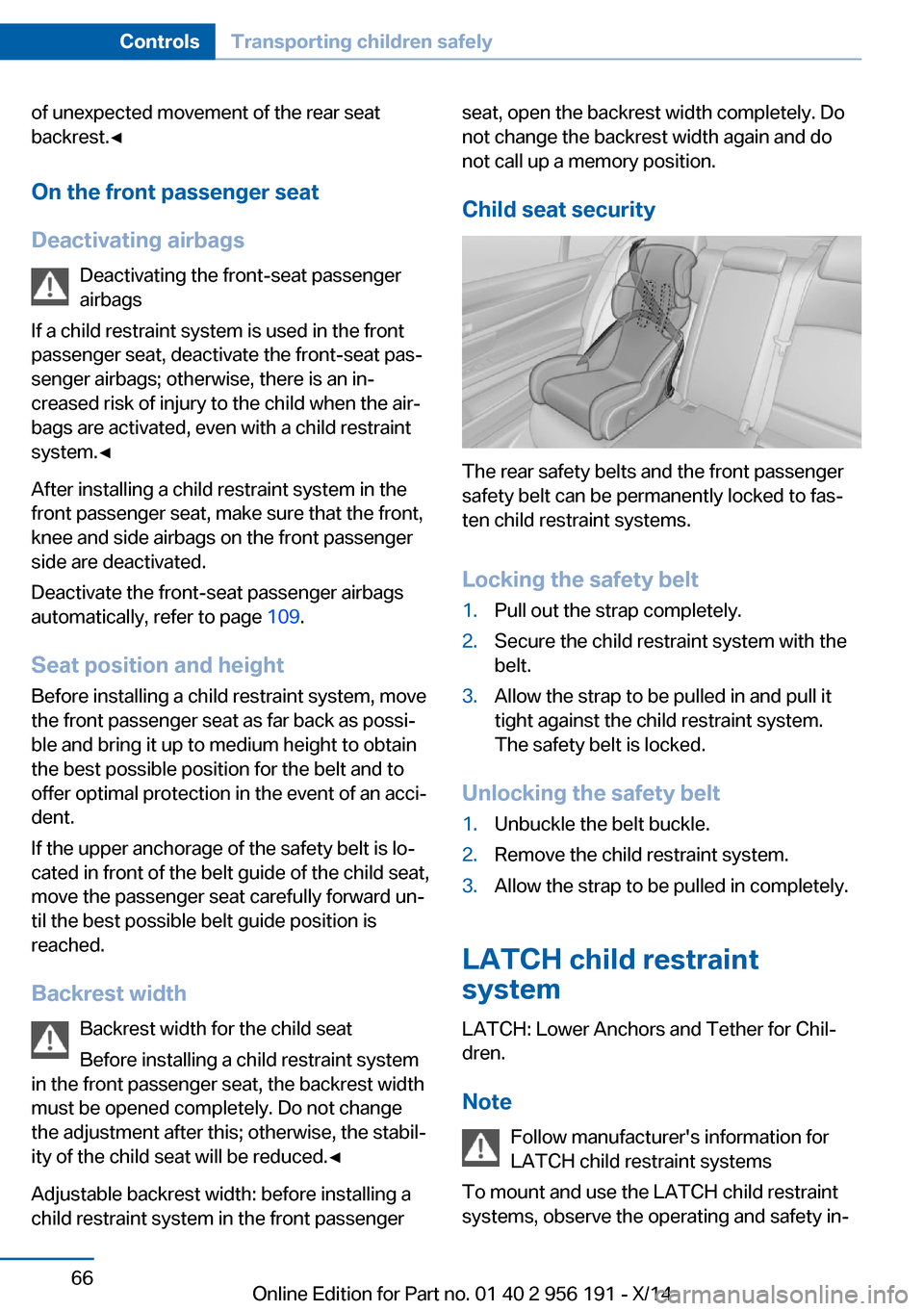
Child seat security
The rear safety belts and the front passenger
safety belt can be permanently locked to fas‐
ten child restraint systems.
Locking the safety belt
1.Pull out the strap completely.2.Secure the child restraint system with the
belt.3.Allow the strap to be pulled in and pull it
tight against the child restraint system.
The safety belt is locked.
Unlocking the safety belt
1.Unbuckle the belt buckle.2.Remove the child restraint system.3.Allow the strap to be pulled in completely.
LATCH child restraint
system
LATCH: Lower Anchors and Tether for Chil‐
dren.
Note Follow manufacturer's information for
LATCH child restraint systems
To mount and use the LATCH child restraint
systems, observe the operating and safety in‐
Seite 66ControlsTransporting children safely66
Online Edition for Part no. 01 40 2 956 191 - X/14
Page 76 of 259

stop, e.g., in traffic congestion or at traffic
lights. The ignition remains switched on. The
engine starts again automatically for driving
off.
Automatic mode After every start of the engine using the Start/
Stop button, the Auto Start/Stop function is in
the last selected state, refer to page 73.
When the Auto Start Stop function is active, it
is available when the vehicle is traveling faster
than about 3 mph, approx. 5 km/h.
Engine stop
The engine is switched off automatically dur‐
ing a stop under the following conditions:
Steptronic transmission:▷The selector lever is in selector lever posi‐
tion D.▷The brake pedal remains pressed while the
vehicle is stationary or the vehicle is held
by Automatic Hold.▷The driver's safety belt is buckled or the
driver's door is closed.
The air flow from the air conditioner is reduced
when the engine is switched off.
Displays in the instrument cluster The display indicates that the
Auto Start/Stop function is
ready for an Automatic engine
start.
The display indicates that the conditions for an automatic en‐
gine stop have not been met.
Note The engine is not switched off automatically in
the following situations:
▷External temperature too low.▷The external temperature is high and auto‐
matic climate control is running.▷The car's interior has not yet been heated
or cooled to the required level.▷The engine is not yet at operating temper‐
ature.▷The wheels are at a sharp angle or the
steering wheel is being turned.▷After driving in reverse.▷Fogging of the windows when the auto‐
matic climate control is switched on.▷Vehicle battery is heavily discharged.▷At higher elevations.▷The engine compartment lid is unlocked.▷HDC Hill Descent Control is activated.▷The parking assistant is activated.▷Stop-and-go traffic.▷The selector lever is in position N, M/S or
R.▷Use of fuel with high ethanol content.
Starting the engine
The engine starts automatically under the fol‐
lowing conditions:
▷Steptronic transmission:
By releasing the brake pedal.
When Automatic Hold is activated: press
the accelerator pedal.
After the engine starts, accelerate as usual.
Safety mode
After the engine switches off automatically, it
will not start again automatically if any one of
the following conditions are met.
▷The driver's safety belt is unbuckled and
the driver's door is open.▷The hood was unlocked.
Some indicator lights light up for a varied
length of time.
Seite 72ControlsDriving72
Online Edition for Part no. 01 40 2 956 191 - X/14
Page 80 of 259
Take the remote control with you
Take the remote control with you when
leaving the vehicle so that children, e.g., can‐
not release the parking brake.◀
Malfunction
In the event of a failure or malfunction of the
parking brake, secure the vehicle against roll‐
ing using a wheel chock, e.g., when leaving it.
Manual release Before releasing, secure the vehicle
against rolling
Before releasing the parking brake manually,
and whenever you park the vehicle with the
parking brake released, ensure that position P
of the Steptronic transmission is set.
Secure the vehicle in a manner appropriate to
the inclination of the road, e.g., with a wheel
chock; otherwise, there is a danger of an acci‐
dent and injuries if the vehicle rolls uninten‐
tionally.◀
The parking brake can be released manually in
the event of a power failure or electrical fault.
Unlocking Have the malfunction corrected
If the parking brake has been released
manually in response to a malfunction, only
technicians can return it to operation.
Have the malfunction corrected by your serv‐
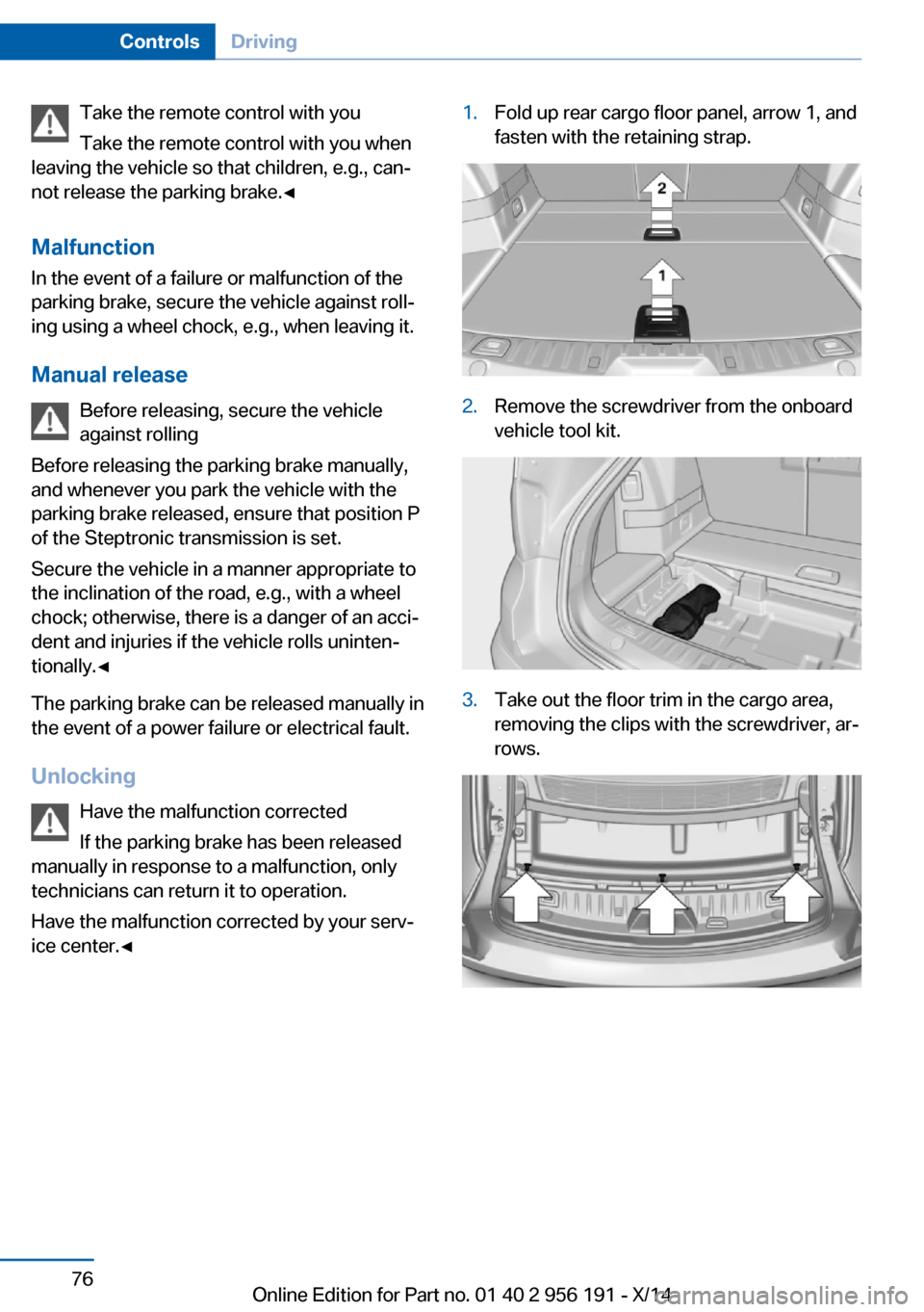
ice center.◀1.Fold up rear cargo floor panel, arrow 1, and
fasten with the retaining strap.2.Remove the screwdriver from the onboard
vehicle tool kit.3.Take out the floor trim in the cargo area,
removing the clips with the screwdriver, ar‐
rows.Seite 76ControlsDriving76
Online Edition for Part no. 01 40 2 956 191 - X/14
Page 85 of 259
Steptronic transmission
Selector lever positions
D Drive Selector lever position for normal vehicle oper‐
ation. All gears for forward travel are activated
automatically.
R is Reverse
Select only when the vehicle is stationary.
N Neutral: The vehicle may roll. Use in automatic car
washes, e.g.
When the ignition is switched off, refer to
page 70, selector lever position P is engaged
automatically.
P Park Select only when the vehicle is stationary. The
drive wheels are blocked.
P is engaged automatically:▷After the engine is switched off when the
vehicle is in radio-ready state, refer to
page 70, or when the ignition is switched
off, refer to page 70, and when position R
or D is set.▷With the ignition off, if selector lever posi‐
tion N is set.▷If the safety belt is unbuckled, the driver's
door is opened, and the brake pedal is not
pressed while the vehicle is stationary and
position D or R is set.
Before exiting the vehicle, make sure that se‐
lector lever position P is set. Otherwise, the ve‐
hicle may begin to move.
Kickdown Kickdown is used to achieve maximum driving
performance. Step on the accelerator pedal
beyond the resistance point at the full throttle
position.
Engaging selector lever positions
Press on the brake pedal until you start
driving
To prevent the vehicle from creeping after you
select a gear, maintain pressure on the brake
pedal until you are ready to start.◀▷It is not possible to shift out of selector
lever position P until the engine is running
and the brake is applied.▷With the vehicle is stationary, press on the
brake pedal before shifting out of P or N;
otherwise, the shift command will not be
executed: shift lock.
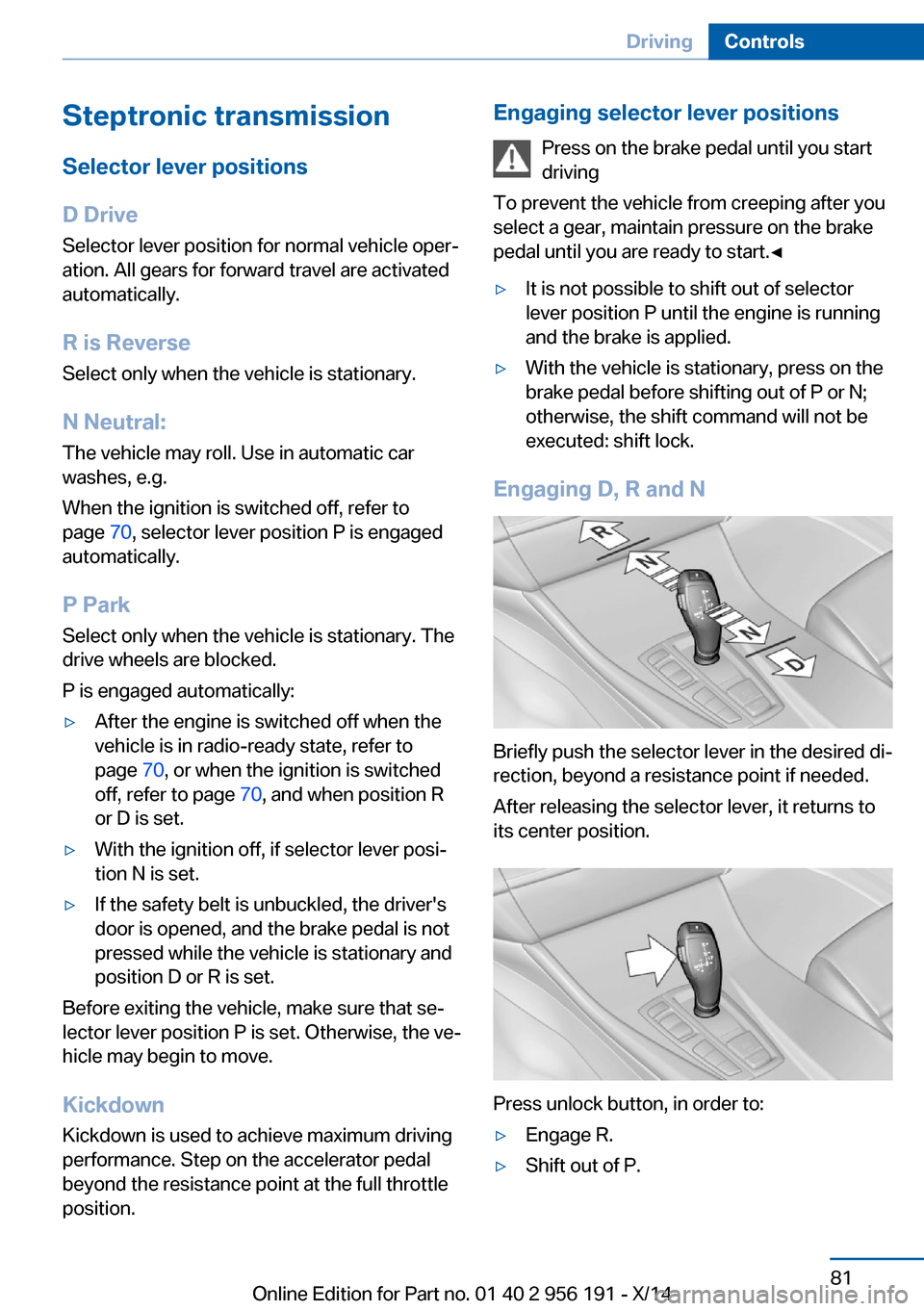
Engaging D, R and N
Briefly push the selector lever in the desired di‐
rection, beyond a resistance point if needed.
After releasing the selector lever, it returns to
its center position.
Press unlock button, in order to:
▷Engage R.▷Shift out of P.Seite 81DrivingControls81
Online Edition for Part no. 01 40 2 956 191 - X/14
Page 87 of 259
If the shift paddles on the steering wheel are
used to shift gears in automatic mode, the
transmission temporarily switches to manual
mode.
If the selector lever is still in selector lever po‐
sition D, it is possible to reel back into the au‐
tomatic mode:▷Pull and hold right shift paddle.
Or
▷In addition to the briefly pulled right shift
paddle, briefly pull the left shift paddle.
In the manual mode, if there has been no ac‐
celeration or shifting of the shift paddles within
a certain amount of time, the transmission
switches back to automatic mode.
Displays in the instrument cluster The selector lever position is dis‐played, e.g.: P.
Electronic unlocking of the
transmission lock
General information Electronically unlock the transmission lock to
maneuver vehicle from the danger area.
Unlocking is possible, if the started can spin
the engine.
Engaging selector lever position N
1.Depress the brake pedal.2.Press the Start/Stop button. The starter
must audibly start.3.Press and hold the selector lever into posi‐
tion N.
A corresponding Check Control message
is displayed.4.Press the selector lever again into posi‐
tion N within approx. 6 seconds.Position N is displayed in the instrument
cluster.5.Release brake, as soon as the starter
stops.6.Maneuver the vehicle from the danger area
and secure it against moving on its own.Seite 83DrivingControls83
Online Edition for Part no. 01 40 2 956 191 - X/14