2014 BMW 435I CONVERTIBLE trunk
[x] Cancel search: trunkPage 164 of 244
Expanding cargo area volume
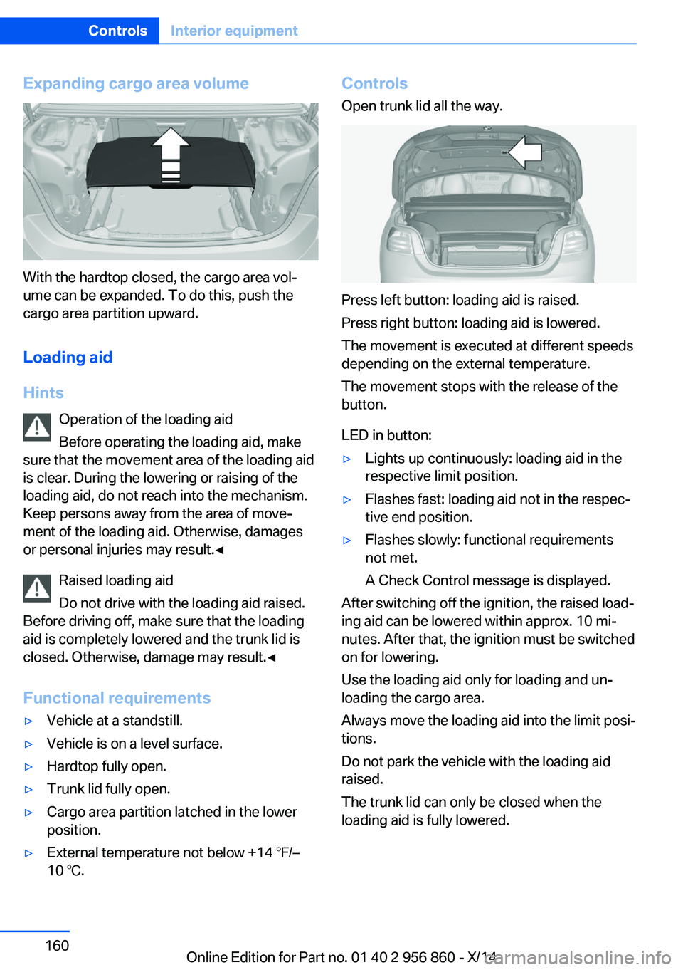
With the hardtop closed, the cargo area vol‐
ume can be expanded. To do this, push the
cargo area partition upward.
Loading aid
Hints Operation of the loading aid
Before operating the loading aid, make
sure that the movement area of the loading aid
is clear. During the lowering or raising of the
loading aid, do not reach into the mechanism.
Keep persons away from the area of move‐
ment of the loading aid. Otherwise, damages
or personal injuries may result.◀
Raised loading aid
Do not drive with the loading aid raised.
Before driving off, make sure that the loading
aid is completely lowered and the trunk lid is
closed. Otherwise, damage may result.◀
Functional requirements
▷Vehicle at a standstill.▷Vehicle is on a level surface.▷Hardtop fully open.▷Trunk lid fully open.▷Cargo area partition latched in the lower
position.▷External temperature not below +14 ℉/–
10 ℃.Controls
Open trunk lid all the way.
Press left button: loading aid is raised.
Press right button: loading aid is lowered.
The movement is executed at different speeds
depending on the external temperature.
The movement stops with the release of the
button.
LED in button:
▷Lights up continuously: loading aid in the
respective limit position.▷Flashes fast: loading aid not in the respec‐
tive end position.▷Flashes slowly: functional requirements
not met.
A Check Control message is displayed.
After switching off the ignition, the raised load‐
ing aid can be lowered within approx. 10 mi‐
nutes. After that, the ignition must be switched
on for lowering.
Use the loading aid only for loading and un‐
loading the cargo area.
Always move the loading aid into the limit posi‐
tions.
Do not park the vehicle with the loading aid
raised.
The trunk lid can only be closed when the
loading aid is fully lowered.
Seite 160ControlsInterior equipment160
Online Edition for Part no. 01 40 2 956 860 - X/14
Page 167 of 244
Storage compartmentsVehicle features and optionsThis chapter describes all standard, country-
specific and optional features offered with the
series. It also describes features that are not
necessarily available in your car, e. g., due to
the selected options or country versions. This
also applies to safety-related functions and
systems.
Hints No loose objects in the car's interior
Do not stow any objects in the car's inte‐
rior without securing them; otherwise, they
may present a danger to occupants e.g., during
braking and evasive maneuvers.◀
Do not place anti-slip mats on the dash‐
board
Do not place anti-slip mats on the dashboard.
The mat materials could damage the dash‐
board.◀
Storage compartments The following storage compartments are avail‐
able in the vehicle interior:▷Glove compartment on the front passenger
side, refer to page 163.▷Glove compartment on the driver's side,
refer to page 164.▷Without Smoker's package: Front storage
compartment, in front of the cupholders,
refer to page 164.▷Storage compartment in the front center
armrest, refer to page 164.▷Compartments in the doors, refer to
page 164.▷Nets on the backrests of the front seats.▷Storage compartment in the rear center
console, refer to page 165.▷Storage compartment between the rear
seats, refer to page 165.
Glove compartment
Front passenger side
Note Close the glove compartment again im‐
mediately
Close the glove compartment immediately af‐
ter use while driving; otherwise, injury may oc‐
cur during accidents.◀
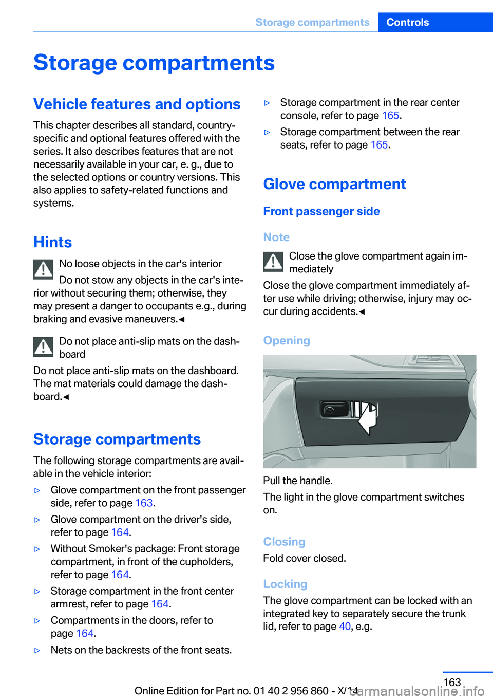
Opening
Pull the handle.
The light in the glove compartment switches
on.
ClosingFold cover closed.
Locking
The glove compartment can be locked with an
integrated key to separately secure the trunk
lid, refer to page 40, e.g.
Seite 163Storage compartmentsControls163
Online Edition for Part no. 01 40 2 956 860 - X/14
Page 172 of 244
Things to remember when drivingVehicle features and options
This chapter describes all standard, country-
specific and optional features offered with the
series. It also describes features that are not
necessarily available in your car, e. g., due to
the selected options or country versions. This
also applies to safety-related functions and
systems.
Breaking-in period
General information Moving parts need time to adjust to one an‐
other (break-in time).
The following instructions will help accomplish
a long vehicle life and good efficiency.
During break-in, do not use the Launch Con‐
trol, refer to page 74.
Engine, transmission, and axle drive Always obey the official speed limit.
Up to 1,200 miles/2,000 km
Do not exceed the maximum engine and road
speed:▷For gasoline engine 4,500 rpm and
100 mph/160 km/h.
Avoid full load or kickdown under all circum‐
stances.
From 1,200 miles/2,000 km The engine and vehicle speed can gradually be
increased.
Tires
Tire traction is not optimal due to manufactur‐
ing circumstances when tires are brand-new;
they achieve their full traction potential after a
break-in time.
Drive conservatively for the first
200 miles/300 km.
Brake system
Brakes require an initial break-in period of ap‐
prox. 300 miles/500 km to achieve optimal per‐
formance between brake discs and brake
pads. Drive moderately during this break-in pe‐
riod.
Following part replacement
The same break-in procedures should be ob‐
served if any of the components above-men‐
tioned have to be renewed in the course of the
vehicle's operating life.
General driving notes
Closing the trunk lid Drive with the trunk lid closed
Only drive with the tailgate closed; other‐
wise, in the event of an accident or braking and
evasive maneuvers, passengers and other traf‐
fic may be injured, and the vehicle may be
damaged. In addition, exhaust fumes may en‐
ter the vehicle interior.◀
If driving with the tailgate open cannot be
avoided:▷If the hardtop is closed, close all windows.▷Greatly increase the air flow from the vents.▷Drive moderately.
Hot exhaust system
Hot exhaust system
High temperatures are generated in the
exhaust system.
Seite 168Driving tipsThings to remember when driving168
Online Edition for Part no. 01 40 2 956 860 - X/14
Page 214 of 244
Outer brake lamp: 21-watt bulb, H21WLL.
The tail lights feature LED technology. Contact
your service center in the event of a malfunc‐
tion.
Use caution when replacing the bulb
Use caution and proceed one step at a
time when replacing the bulbs to prevent dam‐
age to the tail lights or the vehicle.◀
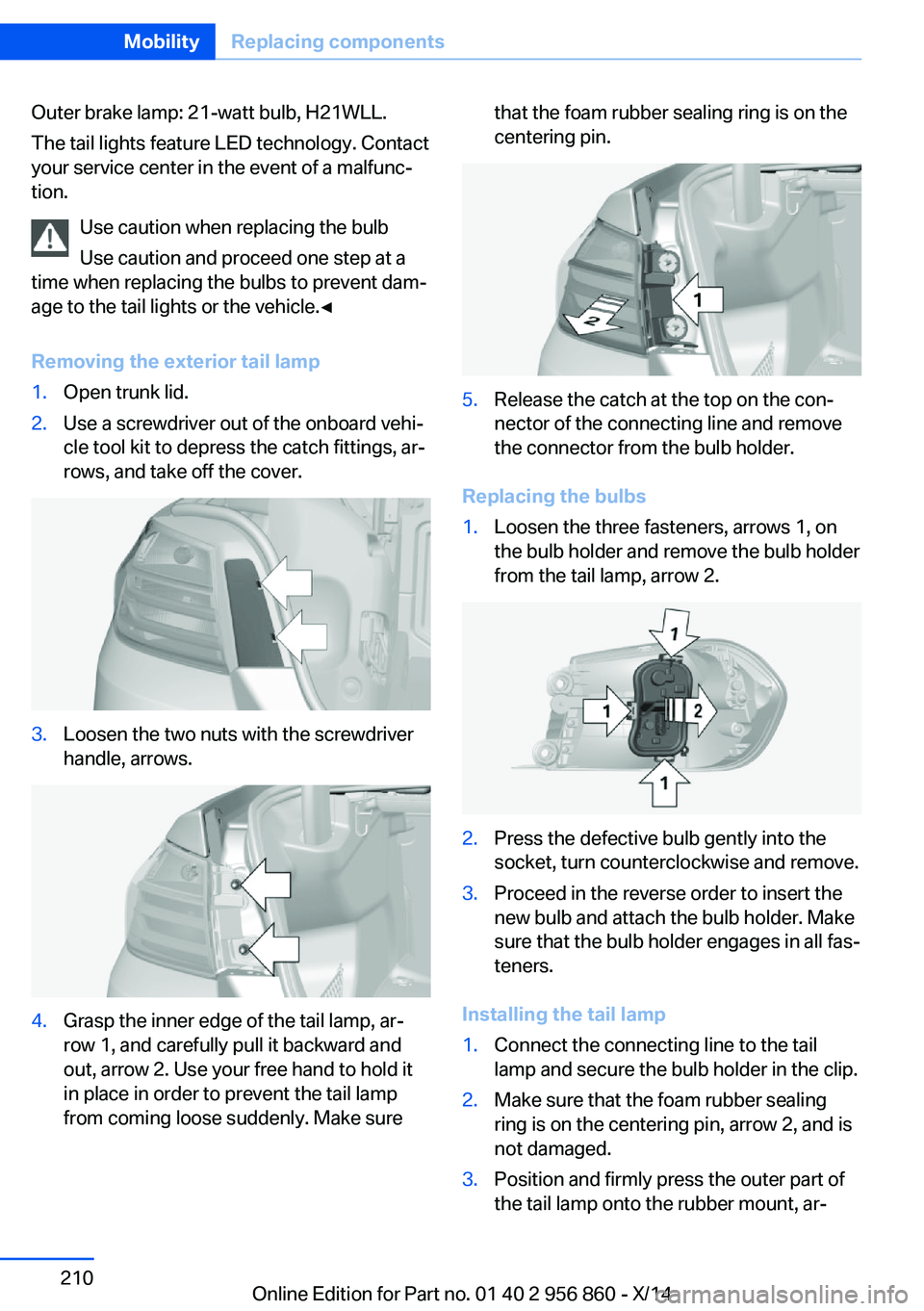
Removing the exterior tail lamp1.Open trunk lid.2.Use a screwdriver out of the onboard vehi‐
cle tool kit to depress the catch fittings, ar‐
rows, and take off the cover.3.Loosen the two nuts with the screwdriver
handle, arrows.4.Grasp the inner edge of the tail lamp, ar‐
row 1, and carefully pull it backward and
out, arrow 2. Use your free hand to hold it
in place in order to prevent the tail lamp
from coming loose suddenly. Make surethat the foam rubber sealing ring is on the
centering pin.5.Release the catch at the top on the con‐
nector of the connecting line and remove
the connector from the bulb holder.
Replacing the bulbs
1.Loosen the three fasteners, arrows 1, on
the bulb holder and remove the bulb holder
from the tail lamp, arrow 2.2.Press the defective bulb gently into the
socket, turn counterclockwise and remove.3.Proceed in the reverse order to insert the
new bulb and attach the bulb holder. Make
sure that the bulb holder engages in all fas‐
teners.
Installing the tail lamp
1.Connect the connecting line to the tail
lamp and secure the bulb holder in the clip.2.Make sure that the foam rubber sealing
ring is on the centering pin, arrow 2, and is
not damaged.3.Position and firmly press the outer part of
the tail lamp onto the rubber mount, ar‐Seite 210MobilityReplacing components210
Online Edition for Part no. 01 40 2 956 860 - X/14
Page 215 of 244
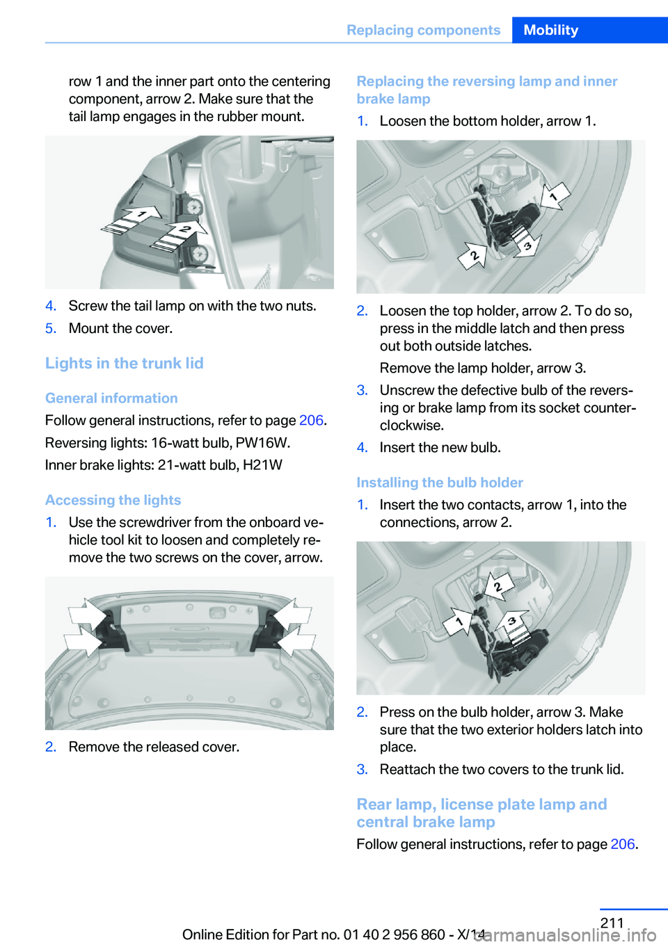
row 1 and the inner part onto the centering
component, arrow 2. Make sure that the
tail lamp engages in the rubber mount.4.Screw the tail lamp on with the two nuts.5.Mount the cover.
Lights in the trunk lid
General information
Follow general instructions, refer to page 206.
Reversing lights: 16-watt bulb, PW16W.
Inner brake lights: 21-watt bulb, H21W
Accessing the lights
1.Use the screwdriver from the onboard ve‐
hicle tool kit to loosen and completely re‐
move the two screws on the cover, arrow.2.Remove the released cover.Replacing the reversing lamp and inner
brake lamp1.Loosen the bottom holder, arrow 1.2.Loosen the top holder, arrow 2. To do so,
press in the middle latch and then press
out both outside latches.
Remove the lamp holder, arrow 3.3.Unscrew the defective bulb of the revers‐
ing or brake lamp from its socket counter‐
clockwise.4.Insert the new bulb.
Installing the bulb holder
1.Insert the two contacts, arrow 1, into the
connections, arrow 2.2.Press on the bulb holder, arrow 3. Make
sure that the two exterior holders latch into
place.3.Reattach the two covers to the trunk lid.
Rear lamp, license plate lamp and
central brake lamp
Follow general instructions, refer to page 206.
Seite 211Replacing componentsMobility211
Online Edition for Part no. 01 40 2 956 860 - X/14
Page 220 of 244
steps to help you under certain circum‐
stances.
For this, data are transmitted to the BMW
Response Center which serve to deter‐
mine the necessary rescue measures. E. g.
the current position of the vehicle, if it can
be established.▷If the LED is flashing green, but the BMW
Response Center can no longer be heard
via the speaker, you can nevertheless still
be heard at the BMW Response Center.
Initiating an Emergency Request
automatically
Under certain conditions, an Emergency Re‐
quest is automatically initiated immediately af‐
ter a severe accident. Automatic Collision Noti‐
fication is not affected by pressing the SOS
button.
Warning triangle
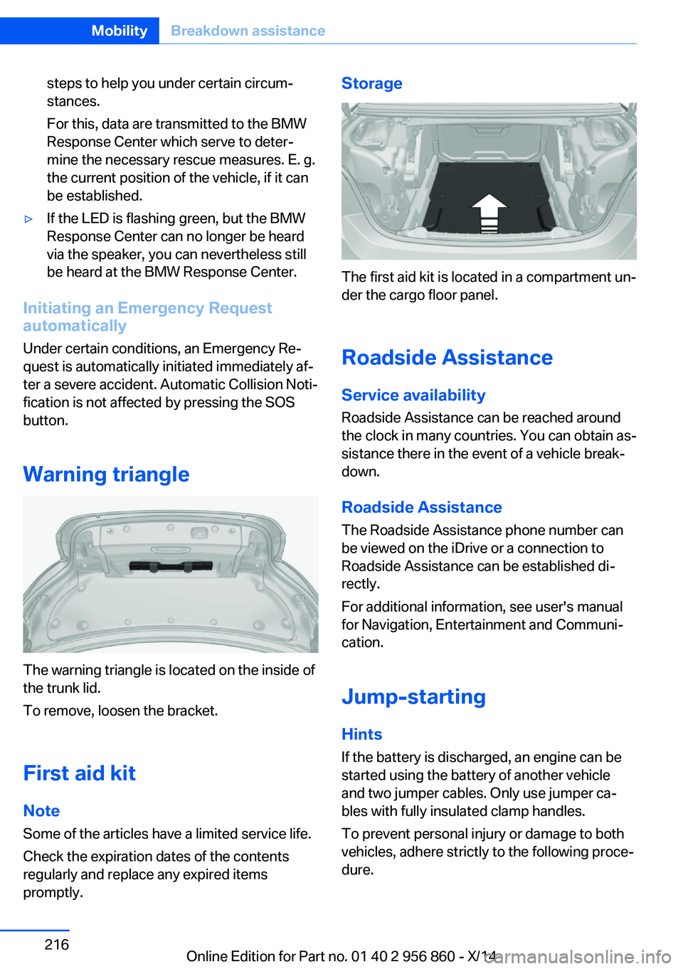
The warning triangle is located on the inside of
the trunk lid.
To remove, loosen the bracket.
First aid kit NoteSome of the articles have a limited service life.
Check the expiration dates of the contents
regularly and replace any expired items
promptly.
Storage
The first aid kit is located in a compartment un‐
der the cargo floor panel.
Roadside Assistance Service availability
Roadside Assistance can be reached around
the clock in many countries. You can obtain as‐
sistance there in the event of a vehicle break‐
down.
Roadside Assistance The Roadside Assistance phone number can
be viewed on the iDrive or a connection to
Roadside Assistance can be established di‐
rectly.
For additional information, see user's manual
for Navigation, Entertainment and Communi‐
cation.
Jump-starting
Hints
If the battery is discharged, an engine can be
started using the battery of another vehicle
and two jumper cables. Only use jumper ca‐
bles with fully insulated clamp handles.
To prevent personal injury or damage to both
vehicles, adhere strictly to the following proce‐
dure.
Seite 216MobilityBreakdown assistance216
Online Edition for Part no. 01 40 2 956 860 - X/14
Page 236 of 244
Convenient closing with theremote control 37
Convenient opening with the remote control 37
Convertible, Hardtop 46
Convertible mode, automatic climate control 146, 149
Convertible program, auto‐ matic climate con‐
trol 146 , 149
Coolant 203
Coolant level 203
Coolant temperature 81
Cooling function 146, 149
Cooling, maximum 149
Cooling system 203
Corrosion on brake discs 170
Cosmetic mirror 157
Cruise control 130
Cruise control, active with Stop & Go 124
Cruising range 81
Cupholders 165
Current fuel consumption 82
D
Damage, tires 194
Damping control, dy‐ namic 121
Data, technical 226
Date 81
Daytime running lights 92
Defrosting, refer to defrosting the windows 146
Defrosting, refer to Windows, defrosting 150
Defrosting the windows 146
Dehumidifying, air 146, 149
Deleting personal data 24
Deletion of personal data 24
Destination distance 86
Digital clock 81
Digital compass 155
Dimensions 226
Dimmable exterior mirrors 59 Dimmable interior rearview
mirror 59
Direction indicator, refer to Turn signals 68
Display, electronic, instru‐ ment cluster 76
Display in windshield 89
Display lighting, refer to In‐ strument lighting 94
Displays, cleaning 223
Disposal, coolant 203
Disposal, vehicle battery 213
Distance control, refer to PDC 132
Distance to destination 86
Divided screen view, split screen 23
Door lock 39
Door lock, refer to Remote control 34
Drive-off assistant 123
Drive-off assistant, refer to DSC 119
Driver assistance, refer to In‐ telligent Safety 105
Driving Assistant, refer to In‐ telligent Safety 105
Driving Dynamics Con‐ trol 121
Driving instructions, break- in 168
Driving mode 121
Driving notes, general 168
Driving stability control sys‐ tems 119
Driving style analysis 179
Driving tips 168
DSC Dynamic Stability Con‐ trol 119
DTC Dynamic Traction Con‐ trol 120
Dynamic Damping Con‐ trol 121
Dynamic Stability Control DSC 119 Dynamic Traction Control
DTC 120
E ECO PRO 175
ECO PRO, bonus range 176
ECO PRO display 175
ECO PRO driving mode 175
ECO PRO driving style analy‐ sis 179
ECO PRO mode 175
ECO PRO Tip - driving in‐ struction 177
EfficientDynamics 177
Electronic displays, instru‐ ment cluster 76
Electronic oil measure‐ ment 200
Electronic Stability Program ESP, refer to DSC 119
Emergency detection, remote control 35
Emergency release, fuel filler flap 184
Emergency Request 215
Emergency service, refer to Roadside Assistance 216
Emergency start function, en‐ gine start 35
Emergency unlocking, trans‐ mission lock 74
Emergency unlocking, trunk lid 41
Energy Control 82
Energy recovery 82
Engine, automatic reel-off 66
Engine, automatic Start/Stop function 66
Engine compartment 198
Engine compartment, work‐ ing in 199
Engine coolant 203
Engine idling when driving, coasting 178
Engine oil 200 Seite 232ReferenceEverything from A to Z232
Online Edition for Part no. 01 40 2 956 860 - X/14
Page 238 of 244
High beams/low beams, referto High-beam Assistant 93
Hills 170
Hill start assistant, refer to Drive-off assistant 123
Hints 6
Holder for beverages 165
Hood 199
Horn 14
Hotel function, trunk lid 40
Hot exhaust system 168
HUD Head-up Display 89
Hydroplaning 169
I Ice warning, see External temperature warning 81
Icy roads, see External tem‐ perature warning 81
Identification marks, tires 192
Identification number, see ve‐ hicle identification num‐
ber 9
iDrive 18
Ignition key, refer to Remote control 34
Ignition off 64
Ignition on 64
Indication of a flat tire 101 , 104
Indicator and alarm lamps, see Check Control 77
Indicator lamp, see Check Control 77
Individual air distribu‐ tion 146, 150
Individual settings, refer to Personal Profile 35
Inflation pressure, tires 188
Inflation pressure warning FTM, tires 104
Info display, refer to Com‐ puter 85
Initialize, Tire Pressure Moni‐ tor TPM 101 Initializing, Flat Tire Monitor
FTM 104
Instrument cluster 76
Instrument cluster, electronic displays 76
Instrument lighting 94
Integrated key 34
Integrated Owner's Manual in the vehicle 29
Intelligent Emergency Re‐ quest 215
Intelligent Safety 105
Intensity, AUTO pro‐ gram 149
Interior equipment 153
Interior lights 94
Interior lights via remote con‐ trol 38
Interior motion sensor 44
Interior rearview mirror, auto‐ matic dimming feature 59
Interior rearview mirror, com‐ pass 155
Interior rearview mirror, man‐ ually dimmable 59
Interval display, service re‐ quirements 82
J Jacking points for the vehicle jack 212
Joystick, Steptronic transmis‐ sion 72
Jump-starting 216
K
Key/remote control 34
Keyless Go, refer to Comfort Access 41
Key Memory, refer to Per‐ sonal Profile 35
Kickdown, Steptronic trans‐ mission 72
Knee airbag 96 L
Lamp replacement 206
Lamp replacement, front 207
Lamp replacement, rear 209
Lane departure warning 114
Lane margin, warning 114
Language on Control Dis‐ play 88
Lashing eyes, securing cargo 172
LATCH child restraint sys‐ tem 63
Launch Control 74
Leather, care 221
LED light, bulb replace‐ ment 208
LEDs, light-emitting di‐ odes 207
Length, vehicle 226
Letters and numbers, enter‐ ing 25
Light alloy wheels, care 222
Light control 92
Light-emitting diodes, LEDs 207
Lighter 157
Lighting 91
Lighting via remote con‐ trol 38
Light reel 91
Lights 91
Lights and bulbs 206
Load 172
Loading 171
Loading aid 159
Loading, see interior equip‐ ment 159
Lock, door 39
Locking/unlocking via door lock 39
Locking/unlocking with re‐ mote control 37
Locking, automatic 43
Locking, settings 42
Locking via trunk lid 40 Seite 234ReferenceEverything from A to Z234
Online Edition for Part no. 01 40 2 956 860 - X/14