Page 138 of 236
At a glance
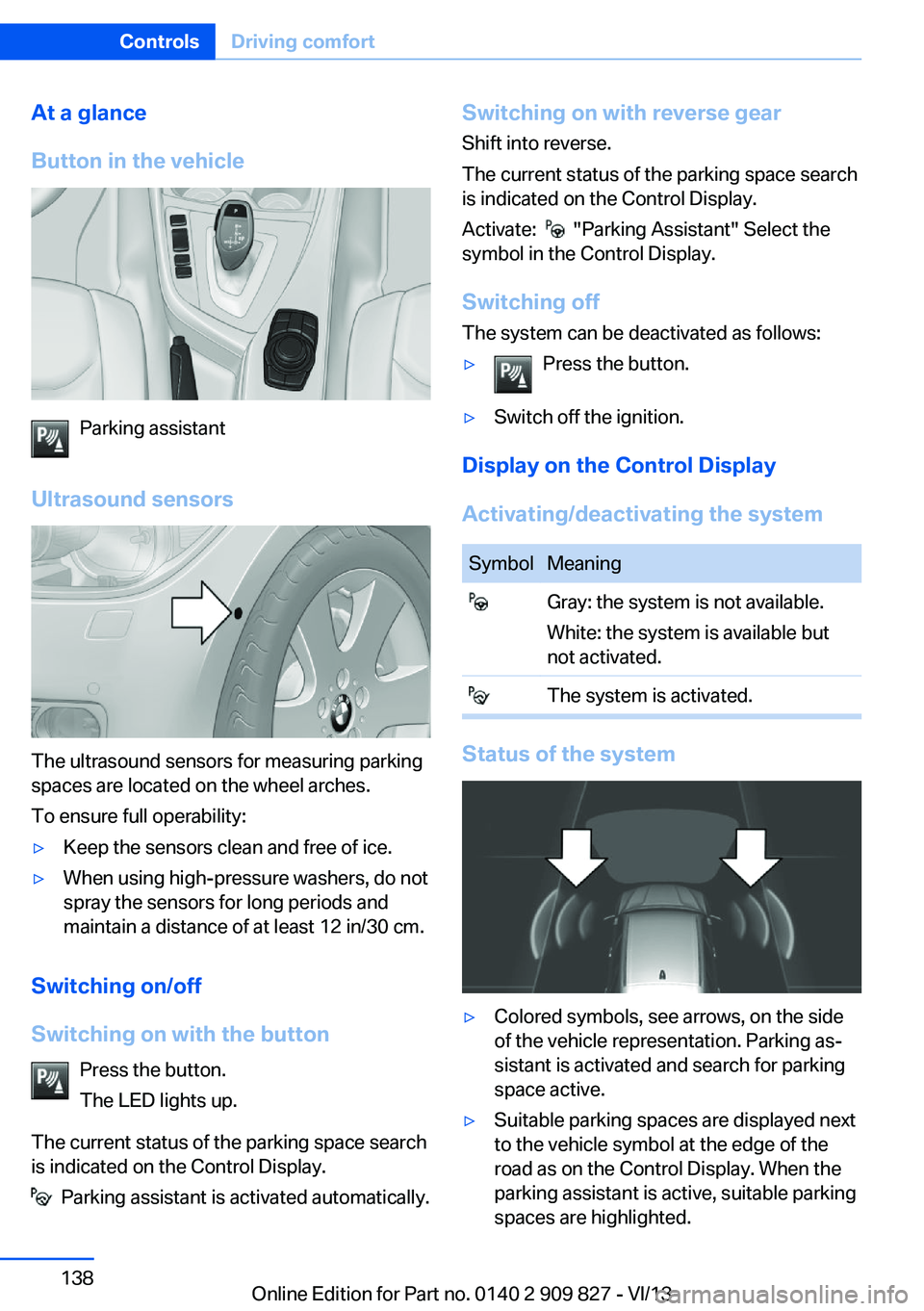
Button in the vehicle
Parking assistant
Ultrasound sensors
The ultrasound sensors for measuring parking
spaces are located on the wheel arches.
To ensure full operability:
▷Keep the sensors clean and free of ice.▷When using high-pressure washers, do not
spray the sensors for long periods and
maintain a distance of at least 12 in/30 cm.
Switching on/off
Switching on with the button Press the button.
The LED lights up.
The current status of the parking space search
is indicated on the Control Display.
Parking assistant is activated automatically.
Switching on with reverse gear
Shift into reverse.
The current status of the parking space search
is indicated on the Control Display.
Activate:
"Parking Assistant" Select the
symbol in the Control Display.
Switching off The system can be deactivated as follows:
▷Press the button.▷Switch off the ignition.
Display on the Control Display
Activating/deactivating the system
SymbolMeaning Gray: the system is not available.
White: the system is available but
not activated. The system is activated.
Status of the system
▷Colored symbols, see arrows, on the side
of the vehicle representation. Parking as‐
sistant is activated and search for parking
space active.▷Suitable parking spaces are displayed next
to the vehicle symbol at the edge of the
road as on the Control Display. When the
parking assistant is active, suitable parking
spaces are highlighted.Seite 138ControlsDriving comfort138
Online Edition for Part no. 0140 2 909 827 - VI/13
Page 140 of 236
▷On bumpy road surfaces such as gravel
roads.▷On slippery ground.▷On steep uphill or downhill grades.▷When leaves or snow has collected in the
parking space.
Limits of ultrasonic measurement
The detection of objects can reach the physi‐
cal limits of ultrasonic measurement, e.g., in
the following circumstances:
▷With tow bars and trailer hitches.▷With thin or wedge-shaped objects.▷With elevated, protruding objects such as
ledges or cargo.▷With objects with corners and sharp edges.▷With objects with a fine surface structure,
such as fences.
Low objects already displayed, e.g., curbs, can
move into the blind area of the sensors before
or after a continuous tone sounds.
High, protruding objects such as ledges may
not be detected.
The parking assistant may identify parking
spaces that are not suitable for parking.
Malfunction
A Check Control message is displayed.
The parking assistant failed. Have the system
checked.
Head-up Display
The concept
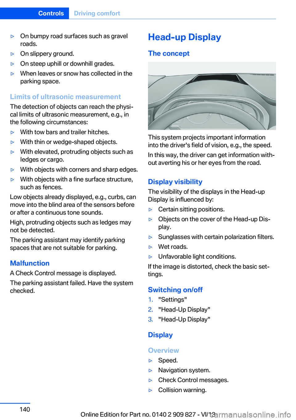
This system projects important information
into the driver's field of vision, e.g., the speed.
In this way, the driver can get information with‐
out averting his or her eyes from the road.
Display visibility The visibility of the displays in the Head-up
Display is influenced by:
▷Certain sitting positions.▷Objects on the cover of the Head-up Dis‐
play.▷Sunglasses with certain polarization filters.▷Wet roads.▷Unfavorable light conditions.
If the image is distorted, check the basic set‐
tings.
Switching on/off
1."Settings"2."Head-Up Display"3."Head-Up Display"
Display
Overview
▷Speed.▷Navigation system.▷Check Control messages.▷Collision warning.Seite 140ControlsDriving comfort140
Online Edition for Part no. 0140 2 909 827 - VI/13
Page 141 of 236
▷Speed limit detection.▷Cruise control.▷Pedestrian warning.▷Selection list from the instrument cluster.
Some of this information is only displayed
briefly as needed.
Selecting displays in the Head-up
Display
1."Settings"2."Head-Up Display"3."Displayed information"4.Select the desired displays in the Head-up
Display.
The settings are stored for the remote control
currently in use.
Setting the brightness
The brightness is automatically adjusted to the
ambient light.
The basic setting can be adjusted manually.
1."Settings"2."Head-Up Display"3."Brightness"4.Turn the controller.
When the low beams are switched on, the
brightness of the Head-up Display can be ad‐
ditionally influenced using the instrument light‐
ing.
The setting is stored for the remote control
currently in use.
Adjusting the height
1."Settings"2."Head-Up Display"3."Height"4.Turn the controller.
The setting is stored for the remote control
currently in use.
Setting the rotation1."Settings"2."Head-Up Display"3."Rotation"4.Turn the controller.
The setting is stored for the remote control
currently in use.
Special windshield
The windshield is part of the system.
The shape of the windshield makes it possible
to display a precise image.
A film in the windshield prevents double im‐
ages from being displayed.
Therefore, have the special windshield re‐
placed by a service center only.
Seite 141Driving comfortControls141
Online Edition for Part no. 0140 2 909 827 - VI/13
Page 148 of 236
Preselecting the switch-on time1."Settings"2."Climate"3."Timer 1:" or "Timer 2:"4.Set the desired time.
Activating the switch-on time
1."Settings"2."Climate"3."Activate timer 1" or "Activate timer 2"
The symbol on the automatic climate con‐
trol lights up when the switch-on time is acti‐
vated.
The symbol on the automatic climate con‐
trol flashes when the system has been
switched on.
The system will only be switched on within the
next 24 hours. After that, it needs to reacti‐
vated.
Seite 148ControlsClimate control148
Online Edition for Part no. 0140 2 909 827 - VI/13
Page 149 of 236
Interior equipmentVehicle equipmentAll standard, country-specific and optional
equipment that is offered in the model series is
described in this chapter. Therefore, equip‐
ment is also described that is not available in a
vehicle, e. g., because of the selected optional
equipment or country variant. This also applies
for safety-related functions and systems.
Integrated universal remote
control
The conceptThe integrated universal remote control can
operate up to 3 functions of remote-controlled
systems such as garage door drives or lighting
systems. The integrated universal remote con‐
trol replaces up to 3 different hand-held trans‐
mitters. To operate the remote control, the
buttons on the interior rearview mirror must be
programmed with the desired functions. The
hand-held transmitter for the particular system
is required in order to program the remote con‐
trol.
During programming
During programming and before activat‐
ing a device using the integrated universal re‐
mote control, ensure that there are no people,
animals, or objects in the range of movement
of the remote-controlled device; otherwise,
there is a risk of injury or damage.
Also follow the safety instructions of the hand-
held transmitter.◀
Before selling the vehicle, delete the stored
functions for the sake of security.Compatibility
If this symbol is printed on the packag‐
ing or in the instructions of the system
to be controlled, the system is gener‐
ally compatible with the integrated universal
remote control.
If you have any questions, please contact:▷Your service center.▷www.homelink.com on the Internet.
HomeLink is a registered trademark of John‐
son Controls, Inc.
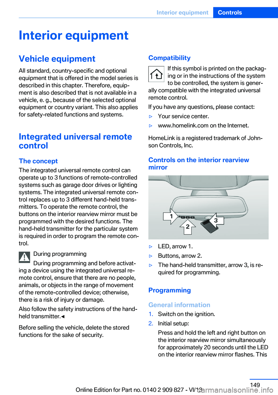
Controls on the interior rearview
mirror
▷LED, arrow 1.▷Buttons, arrow 2.▷The hand-held transmitter, arrow 3, is re‐
quired for programming.
Programming
General information
1.Switch on the ignition.2.Initial setup:
Press and hold the left and right button on
the interior rearview mirror simultaneously
for approximately 20 seconds until the LED
on the interior rearview mirror flashes. ThisSeite 149Interior equipmentControls149
Online Edition for Part no. 0140 2 909 827 - VI/13
Page 153 of 236
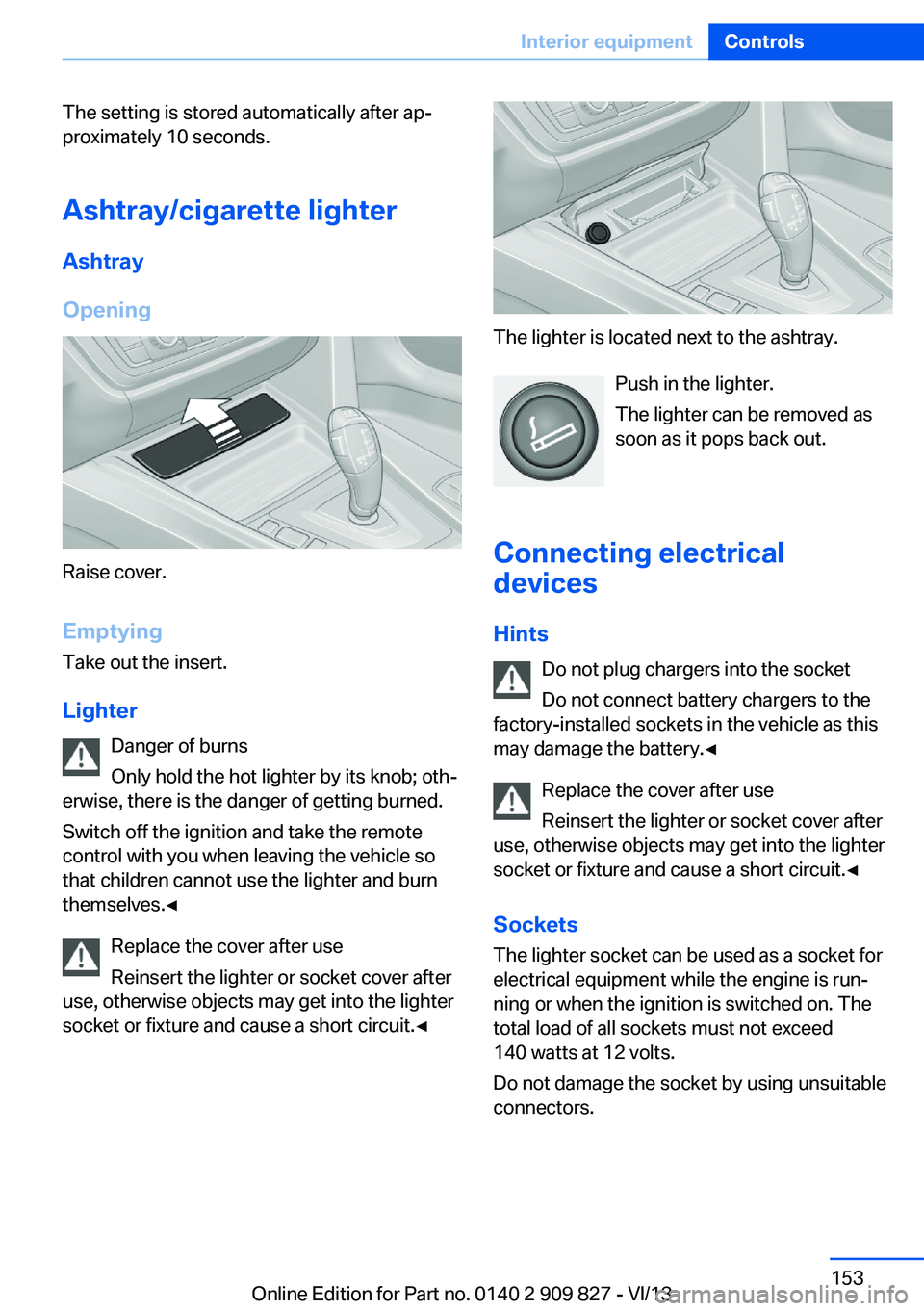
The setting is stored automatically after ap‐
proximately 10 seconds.
Ashtray/cigarette lighter
Ashtray
Opening
Raise cover.
EmptyingTake out the insert.
Lighter Danger of burns
Only hold the hot lighter by its knob; oth‐
erwise, there is the danger of getting burned.
Switch off the ignition and take the remote
control with you when leaving the vehicle so
that children cannot use the lighter and burn
themselves.◀
Replace the cover after use
Reinsert the lighter or socket cover after
use, otherwise objects may get into the lighter
socket or fixture and cause a short circuit.◀
The lighter is located next to the ashtray.
Push in the lighter.
The lighter can be removed as
soon as it pops back out.
Connecting electrical devices
Hints Do not plug chargers into the socket
Do not connect battery chargers to the
factory-installed sockets in the vehicle as this
may damage the battery.◀
Replace the cover after use
Reinsert the lighter or socket cover after
use, otherwise objects may get into the lighter
socket or fixture and cause a short circuit.◀
Sockets
The lighter socket can be used as a socket for
electrical equipment while the engine is run‐
ning or when the ignition is switched on. The
total load of all sockets must not exceed
140 watts at 12 volts.
Do not damage the socket by using unsuitable
connectors.
Seite 153Interior equipmentControls153
Online Edition for Part no. 0140 2 909 827 - VI/13
Page 154 of 236
Front center console
Raise the cap and remove the cover or ciga‐
rette lighter.
In the front passenger footwell
The socket is located below the glove com‐
partment.
Rear center console
Remove the cover.
In the cargo area
The socket is located on the left side in the
cargo area.
USB interface for data
transfer
The concept Connection for importing and exporting data
on USB devices, e.g.:
▷Personal Profile settings, refer to page 34.▷Music collection, see user's manual for
Navigation, Entertainment and Communi‐
cation.▷Importing trips, see user's manual for Navi‐
gation, Entertainment, Communication.
Without Professional navigation
system or TV: at a glance
The USB interface is located in the glove com‐
partment.
Seite 154ControlsInterior equipment154
Online Edition for Part no. 0140 2 909 827 - VI/13
Page 156 of 236
2.The unlocked backrest moves forward
slightly.3.Fold backrest forward.
Closing
Return the rear seat backrest to the upright
seating position and engage it.
Ensure that the lock is securely engaged
Make sure that the lock engages prop‐
erly when folding back, otherwise transported
cargo could enter the passenger compartment
during braking or evasive maneuvers and en‐
danger the vehicle occupants.◀
To secure cargo, refer to page 168, with nets
or draw straps, the cargo area is fitted with
lashing eyes.
Folding down the middle section
Reach into the recess and pull the middle sec‐
tion forward.
Seite 156ControlsInterior equipment156
Online Edition for Part no. 0140 2 909 827 - VI/13