2014 BMW 428I XDRIVE COUPE wheel
[x] Cancel search: wheelPage 124 of 236

Distance displayThe system has been interrupted or
distance control is deactivated be‐
cause the accelerator is being
pressed; a vehicle was not detected.Distance control is deactivated be‐
cause the accelerator is being
pressed; a vehicle was detected.Rolling bars: the detected vehicle has driven
away.
Indicator/warning lamps
Personal responsibility
The indicator and warning lamps do not
relieve the driver of the responsibility to adapt
his or her desired driving speed and style to
the traffic conditions.◀
The vehicle symbol lights up orange:
A vehicle has been detected ahead of
you.
The vehicle symbol flashes orange:
The conditions are not adequate for
operating the system.
The system was deactivated but applies the
brakes until you actively assume control by
pressing on the brake pedal or accelerator.
The vehicle symbol flashes red and an
acoustic signal sounds:
You are requested to intervene by
braking or making an evasive maneuver.
System limits
Speed range Best results are achieved when using the sys‐
tem on well-developed roads and highways.
The desired speed can be selected between
20 mph/30 km/h to 110 mph/180 km/h.
The system can also be activated when sta‐
tionary.
Comply with the legal speed limit in every sit‐
uation when using the system.
Detection range
The detection capacity of the system and the
automatic braking capacity are limited.
Two-wheeled vehicles driving ahead of you
for instance might not be detected.
Limited detection capacity
Because of the limits to the detection ca‐
pacity of the camera and the sensor, you
should be alert at all times so that you can in‐
tervene actively, if necessary; otherwise, there
is the danger of an accident occurring.◀
Deceleration
The system does not decelerate when a sta‐
tionary obstacle is located in the same lane,
e.g., a vehicle at a red traffic light or at the end
of traffic congestion.
The system also does not respond to:
▷Pedestrians or similar slow-moving road
users.▷Red traffic lights.▷Stationary objects.▷Cross traffic.▷Oncoming traffic.Seite 124ControlsDriving comfort124
Online Edition for Part no. 0140 2 909 827 - VI/13
Page 126 of 236

When approaching a curve, the system may
react briefly to the vehicles in the next lane due
to the bend of the curve. Any deceleration of
the vehicle by the system can be compensated
for by briefly accelerating. After the accelerator
pedal is released, the system becomes active
again and independently controls the speed.
Driving away In some situations, the vehicle cannot drive
away automatically, e.g., on steep inclines or
behind bumps in the road.
Radar sensor
For US owners only
The transmitter and receiver units comply with
part 15 of the FCC/Federal Communication
Commission regulations. Operation is gov‐
erned by the following:
FCC ID:
▷OAYARS3-A
Compliance statement:
This device complies with part 15 of the FCC
Rules. Operation is subject to the following
two conditions:
▷This device may not cause harmful inter‐
ference, and▷this device must accept any interference
received, including interference that may
cause undesired operation.
Any unauthorized modifications or changes to
these devices could void the user's authority to
operate this equipment.
Malfunction
The system cannot be activated if the radar
sensor is not aligned correctly. This may be
caused by damage incurred during parking, for
example.
A Check Control message is displayed if the
system fails.
Cruise control
The concept The system is functional at speeds beginning
at approx. 20 mph/30 km/h.
It maintains the speed that was set using the
control elements on the steering wheel.
The system brakes on downhill gradients if en‐
gine braking action is insufficient.
Unfavorable conditions
Do not use the system if unfavorable
conditions make it impossible to drive at a con‐
stant speed, for instance:▷On curvy roads.▷In heavy traffic.▷On slippery roads, in fog, snow or rain, or
on a loose road surface.
Otherwise, you could lose control of the vehi‐
cle and cause an accident.◀
General information
When ECO PRO is activated, cruise control is
also set to a driving style that saves on fuel
consumption.
Seite 126ControlsDriving comfort126
Online Edition for Part no. 0140 2 909 827 - VI/13
Page 127 of 236
Controls
At a glancePress the buttonFunctionInterrupt system on/offStore speedResume speedChanging the speed
Switching on Press the button on the steering
wheel.
The marking in the speedometer is set to the
current speed.
Cruise control can be used.
Switching off Deactivated or interrupted system
If the system is deactivated or inter‐
rupted, actively intervene by braking and, if
necessary, with evasive maneuvers; otherwise,
there is the danger of an accident occurring.◀
Press the button.
▷If active: press twice.▷If interrupted: press once.
The displays go out. The stored desired speed
is deleted.
Interrupting the system When active, press the button.
The system is automatically interrupted if:
▷The brakes are applied.▷The clutch pedal is depressed for a few
seconds or released while a gear is not en‐
gaged.▷The gear engaged is too high for the cur‐
rent speed.▷The transmission position D is disengaged.▷DTC Dynamic Traction Control is activated
or DSC is deactivated.▷DSC is actively controlling stability.
Maintaining/storing the current speed
Press the button.
Or
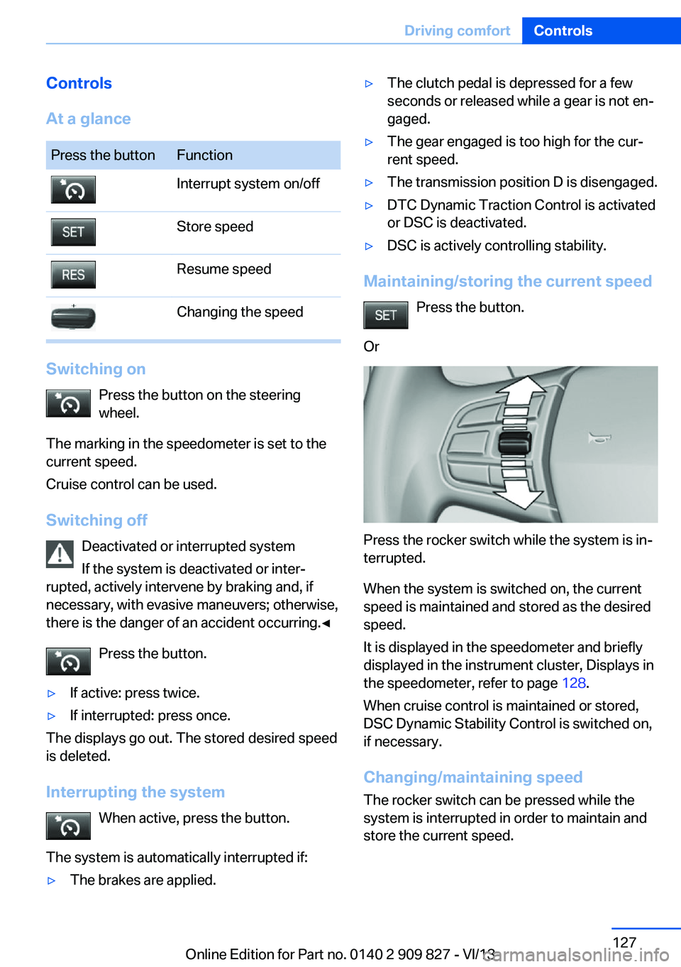
Press the rocker switch while the system is in‐
terrupted.
When the system is switched on, the current
speed is maintained and stored as the desired
speed.
It is displayed in the speedometer and briefly
displayed in the instrument cluster, Displays in
the speedometer, refer to page 128.
When cruise control is maintained or stored,
DSC Dynamic Stability Control is switched on,
if necessary.
Changing/maintaining speed The rocker switch can be pressed while the
system is interrupted in order to maintain and
store the current speed.
Seite 127Driving comfortControls127
Online Edition for Part no. 0140 2 909 827 - VI/13
Page 132 of 236
Switching on/off manuallyPress the button.▷On: the LED lights up.▷Off: the LED goes out.
The PDC is shown on the Control Display.
Switching on the rearview camera via
the iDrive
With PDC activated or Top View switched on:
"Rear view camera"
The rearview camera image is displayed. The
setting is stored for the remote control cur‐
rently in use.
Display on the Control Display
Functional requirement
▷The rearview camera is switched on.▷The trunk lid is fully closed.
Activating the assistance functions
More than one assistance function can be ac‐
tive at the same time.
▷Parking aid lines
"Parking aid lines"
Pathway and turning circle lines are dis‐
played.
▷Obstacle marking
"Obstacle marking"
Spatially-shaped markings are displayed.
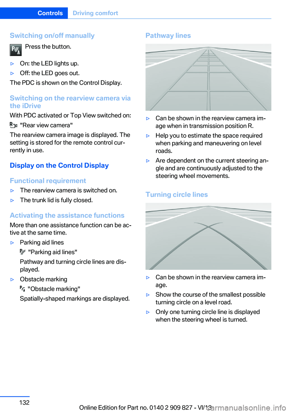
Pathway lines▷Can be shown in the rearview camera im‐
age when in transmission position R.▷Help you to estimate the space required
when parking and maneuvering on level
roads.▷Are dependent on the current steering an‐
gle and are continuously adjusted to the
steering wheel movements.
Turning circle lines
▷Can be shown in the rearview camera im‐
age.▷Show the course of the smallest possible
turning circle on a level road.▷Only one turning circle line is displayed
when the steering wheel is turned.Seite 132ControlsDriving comfort132
Online Edition for Part no. 0140 2 909 827 - VI/13
Page 133 of 236
Obstacle marking
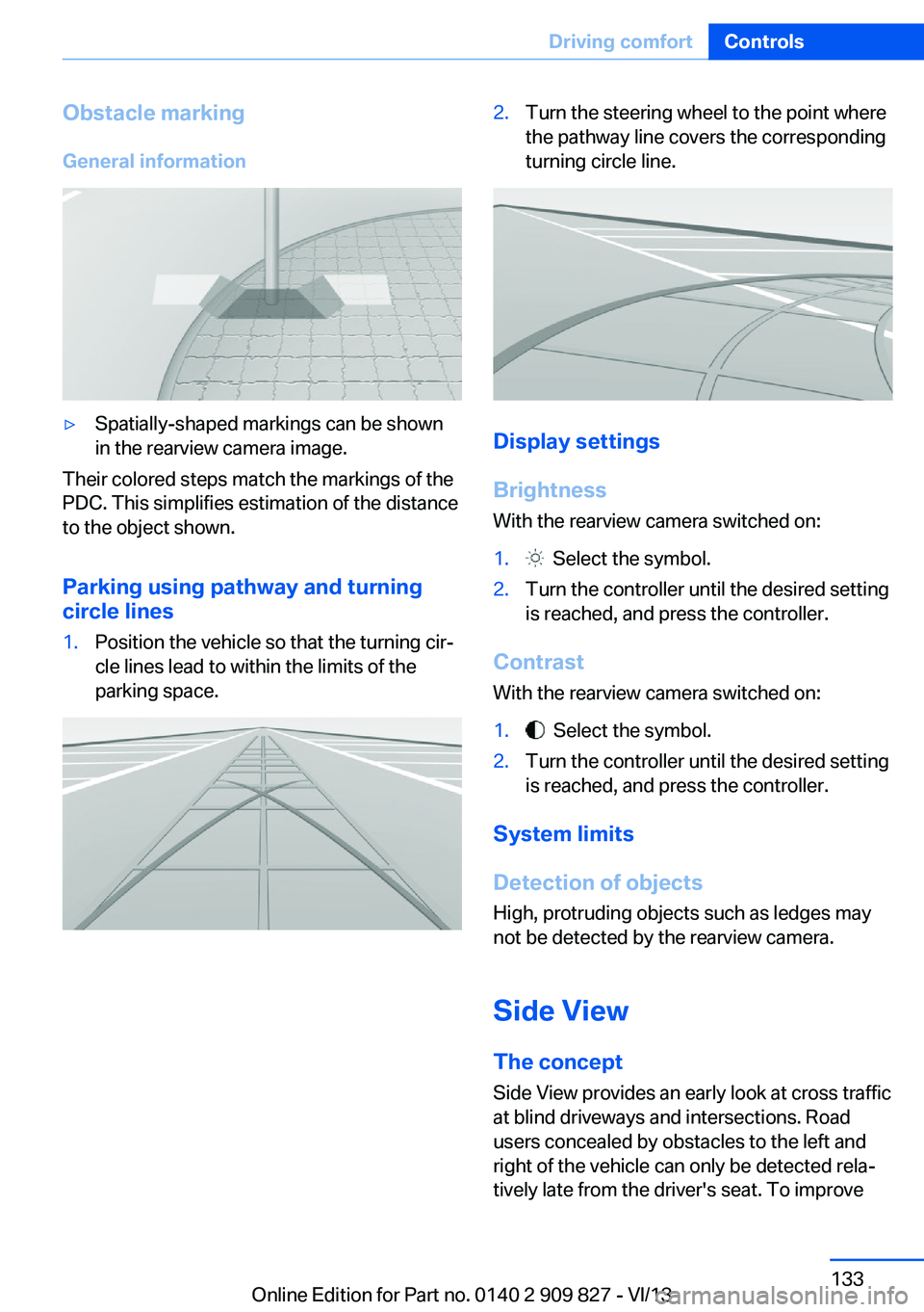
General information▷Spatially-shaped markings can be shown
in the rearview camera image.
Their colored steps match the markings of the
PDC. This simplifies estimation of the distance
to the object shown.
Parking using pathway and turning
circle lines
1.Position the vehicle so that the turning cir‐
cle lines lead to within the limits of the
parking space.2.Turn the steering wheel to the point where
the pathway line covers the corresponding
turning circle line.
Display settings
Brightness
With the rearview camera switched on:
1. Select the symbol.2.Turn the controller until the desired setting
is reached, and press the controller.
Contrast
With the rearview camera switched on:
1. Select the symbol.2.Turn the controller until the desired setting
is reached, and press the controller.
System limits
Detection of objects
High, protruding objects such as ledges may
not be detected by the rearview camera.
Side View The concept Side View provides an early look at cross traffic
at blind driveways and intersections. Road
users concealed by obstacles to the left and
right of the vehicle can only be detected rela‐
tively late from the driver's seat. To improve
Seite 133Driving comfortControls133
Online Edition for Part no. 0140 2 909 827 - VI/13
Page 136 of 236
Switching on the backup camera via
the iDrive
With Top View switched on:
"Rear view camera"
The backup camera image is displayed. The
setting is stored for the remote control cur‐
rently in use.
Display
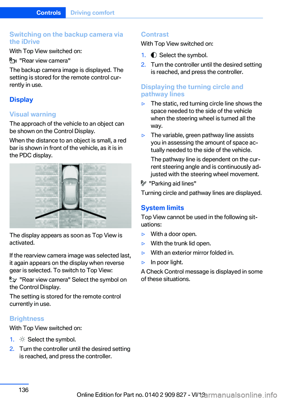
Visual warning The approach of the vehicle to an object can
be shown on the Control Display.
When the distance to an object is small, a red
bar is shown in front of the vehicle, as it is in
the PDC display.
The display appears as soon as Top View is
activated.
If the rearview camera image was selected last,
it again appears on the display when reverse
gear is selected. To switch to Top View:
"Rear view camera" Select the symbol on
the Control Display.
The setting is stored for the remote control
currently in use.
Brightness
With Top View switched on:
1. Select the symbol.2.Turn the controller until the desired setting
is reached, and press the controller.Contrast
With Top View switched on:1. Select the symbol.2.Turn the controller until the desired setting
is reached, and press the controller.
Displaying the turning circle and
pathway lines
▷The static, red turning circle line shows the
space needed to the side of the vehicle
when the steering wheel is turned all the
way.▷The variable, green pathway line assists
you in assessing the amount of space ac‐
tually needed to the side of the vehicle.
The pathway line is dependent on the cur‐
rent steering angle and is continuously ad‐
justed with the steering wheel movement.
"Parking aid lines"
Turning circle and pathway lines are displayed.
System limits
Top View cannot be used in the following sit‐
uations:
▷With a door open.▷With the trunk lid open.▷With an exterior mirror folded in.▷In poor light.
A Check Control message is displayed in some
of these situations.
Seite 136ControlsDriving comfort136
Online Edition for Part no. 0140 2 909 827 - VI/13
Page 137 of 236
Parking assistantThe concept
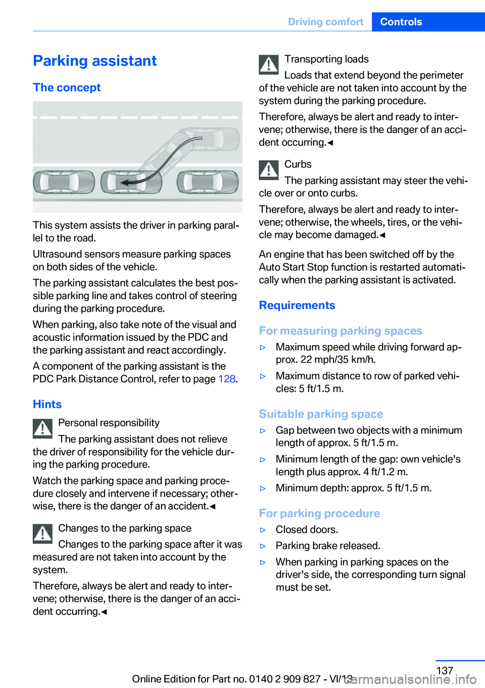
This system assists the driver in parking paral‐
lel to the road.
Ultrasound sensors measure parking spaces
on both sides of the vehicle.
The parking assistant calculates the best pos‐
sible parking line and takes control of steering
during the parking procedure.
When parking, also take note of the visual and
acoustic information issued by the PDC and
the parking assistant and react accordingly.
A component of the parking assistant is the
PDC Park Distance Control, refer to page 128.
Hints Personal responsibility
The parking assistant does not relieve
the driver of responsibility for the vehicle dur‐
ing the parking procedure.
Watch the parking space and parking proce‐
dure closely and intervene if necessary; other‐
wise, there is the danger of an accident.◀
Changes to the parking space
Changes to the parking space after it was
measured are not taken into account by the
system.
Therefore, always be alert and ready to inter‐
vene; otherwise, there is the danger of an acci‐
dent occurring.◀
Transporting loads
Loads that extend beyond the perimeter
of the vehicle are not taken into account by the
system during the parking procedure.
Therefore, always be alert and ready to inter‐
vene; otherwise, there is the danger of an acci‐
dent occurring.◀
Curbs
The parking assistant may steer the vehi‐
cle over or onto curbs.
Therefore, always be alert and ready to inter‐
vene; otherwise, the wheels, tires, or the vehi‐
cle may become damaged.◀
An engine that has been switched off by the
Auto Start Stop function is restarted automati‐
cally when the parking assistant is activated.
Requirements
For measuring parking spaces▷Maximum speed while driving forward ap‐
prox. 22 mph/35 km/h.▷Maximum distance to row of parked vehi‐
cles: 5 ft/1.5 m.
Suitable parking space
▷Gap between two objects with a minimum
length of approx. 5 ft/1.5 m.▷Minimum length of the gap: own vehicle's
length plus approx. 4 ft/1.2 m.▷Minimum depth: approx. 5 ft/1.5 m.
For parking procedure
▷Closed doors.▷Parking brake released.▷When parking in parking spaces on the
driver's side, the corresponding turn signal
must be set.Seite 137Driving comfortControls137
Online Edition for Part no. 0140 2 909 827 - VI/13
Page 138 of 236
At a glance
Button in the vehicle
Parking assistant
Ultrasound sensors
The ultrasound sensors for measuring parking
spaces are located on the wheel arches.
To ensure full operability:
▷Keep the sensors clean and free of ice.▷When using high-pressure washers, do not
spray the sensors for long periods and
maintain a distance of at least 12 in/30 cm.
Switching on/off
Switching on with the button Press the button.
The LED lights up.
The current status of the parking space search
is indicated on the Control Display.
Parking assistant is activated automatically.
Switching on with reverse gear
Shift into reverse.
The current status of the parking space search
is indicated on the Control Display.
Activate:
"Parking Assistant" Select the
symbol in the Control Display.
Switching off The system can be deactivated as follows:
▷Press the button.▷Switch off the ignition.
Display on the Control Display
Activating/deactivating the system
SymbolMeaning Gray: the system is not available.
White: the system is available but
not activated. The system is activated.
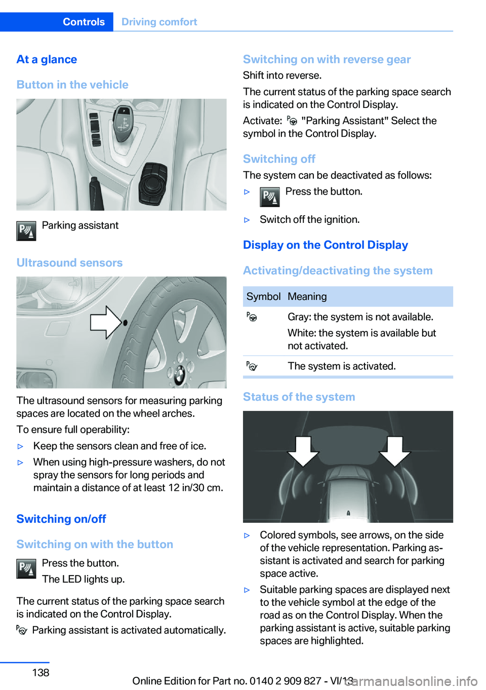
Status of the system
▷Colored symbols, see arrows, on the side
of the vehicle representation. Parking as‐
sistant is activated and search for parking
space active.▷Suitable parking spaces are displayed next
to the vehicle symbol at the edge of the
road as on the Control Display. When the
parking assistant is active, suitable parking
spaces are highlighted.Seite 138ControlsDriving comfort138
Online Edition for Part no. 0140 2 909 827 - VI/13