2014 BMW 428I XDRIVE COUPE ECU
[x] Cancel search: ECUPage 169 of 236
Roof drip rail with flaps
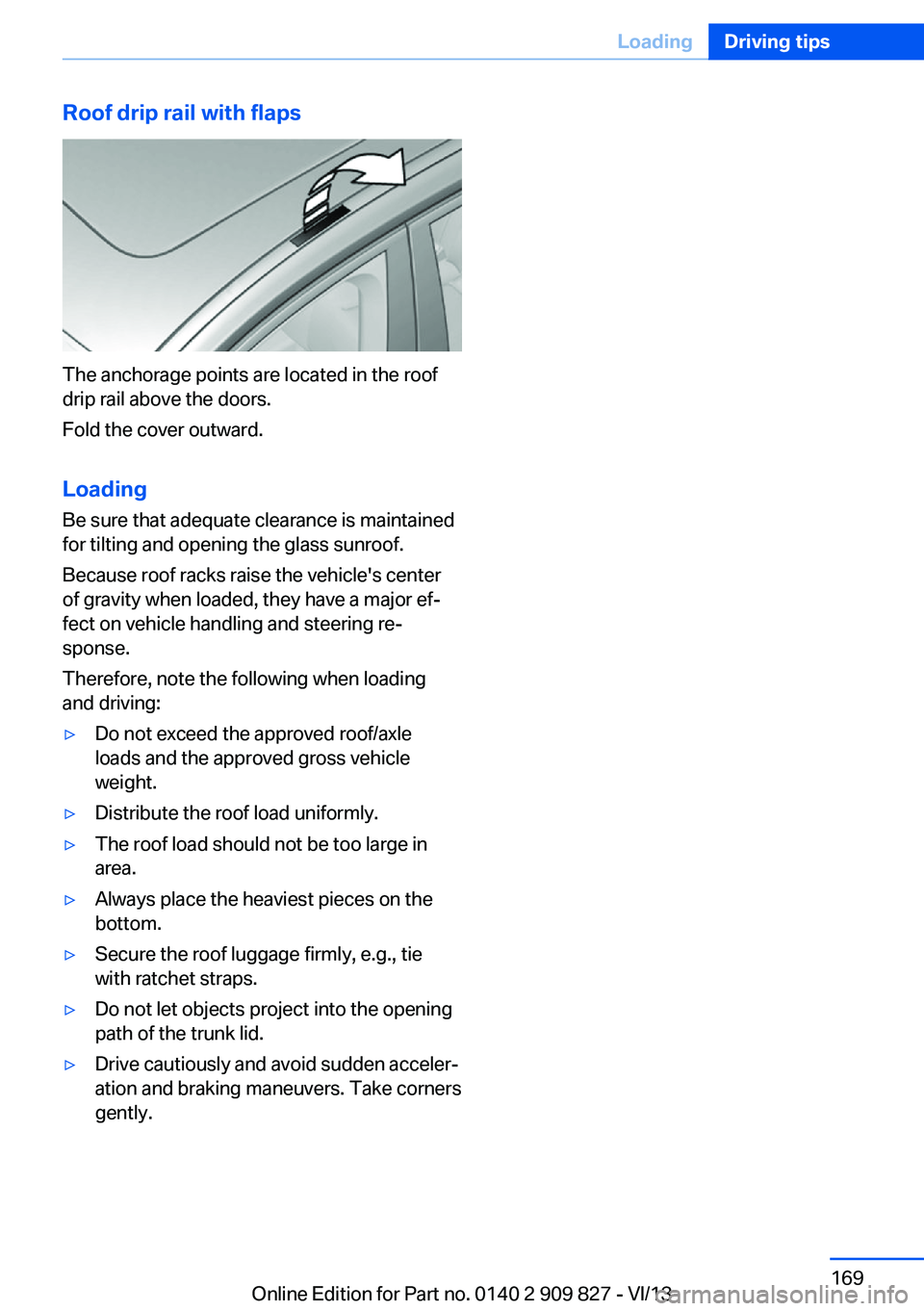
The anchorage points are located in the roof
drip rail above the doors.
Fold the cover outward.
Loading Be sure that adequate clearance is maintained
for tilting and opening the glass sunroof.
Because roof racks raise the vehicle's center
of gravity when loaded, they have a major ef‐
fect on vehicle handling and steering re‐
sponse.
Therefore, note the following when loading
and driving:
▷Do not exceed the approved roof/axle
loads and the approved gross vehicle
weight.▷Distribute the roof load uniformly.▷The roof load should not be too large in
area.▷Always place the heaviest pieces on the
bottom.▷Secure the roof luggage firmly, e.g., tie
with ratchet straps.▷Do not let objects project into the opening
path of the trunk lid.▷Drive cautiously and avoid sudden acceler‐
ation and braking maneuvers. Take corners
gently.Seite 169LoadingDriving tips169
Online Edition for Part no. 0140 2 909 827 - VI/13
Page 191 of 236
Hood
Hints Working in the engine compartment
Never attempt to perform any service or
repair operations on your vehicle without the
necessary professional technical training.
If you are unfamiliar with the statutory guide‐
lines, have any work on the vehicle performed
only by a service center.
If this work is not carried out properly, there is
the danger of subsequent damage and related
safety hazards.◀
Never reach into the engine compart‐
ment
Never reach into the intermediate spaces or
gaps in the engine compartment. Otherwise,
there is risk of injury, e.g., from rotating or hot
parts.◀
Fold down wiper arm
Before opening the hood, ensure that the
wiper arms are against the windshield, or this
may result in damage.◀
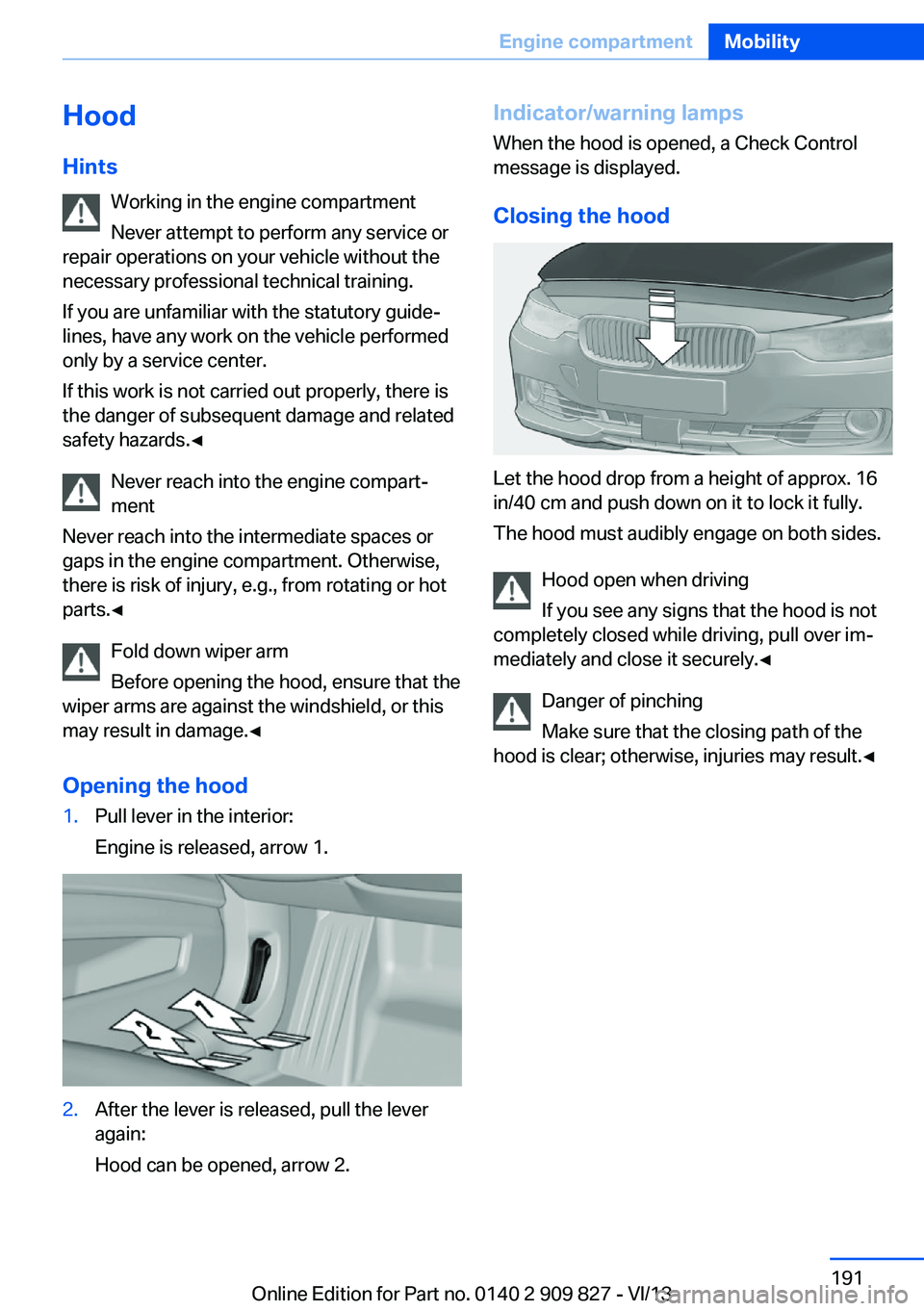
Opening the hood1.Pull lever in the interior:
Engine is released, arrow 1.2.After the lever is released, pull the lever
again:
Hood can be opened, arrow 2.Indicator/warning lamps
When the hood is opened, a Check Control
message is displayed.
Closing the hood
Let the hood drop from a height of approx. 16
in/40 cm and push down on it to lock it fully.
The hood must audibly engage on both sides.
Hood open when driving
If you see any signs that the hood is not
completely closed while driving, pull over im‐
mediately and close it securely.◀
Danger of pinching
Make sure that the closing path of the
hood is clear; otherwise, injuries may result.◀
Seite 191Engine compartmentMobility191
Online Edition for Part no. 0140 2 909 827 - VI/13
Page 205 of 236
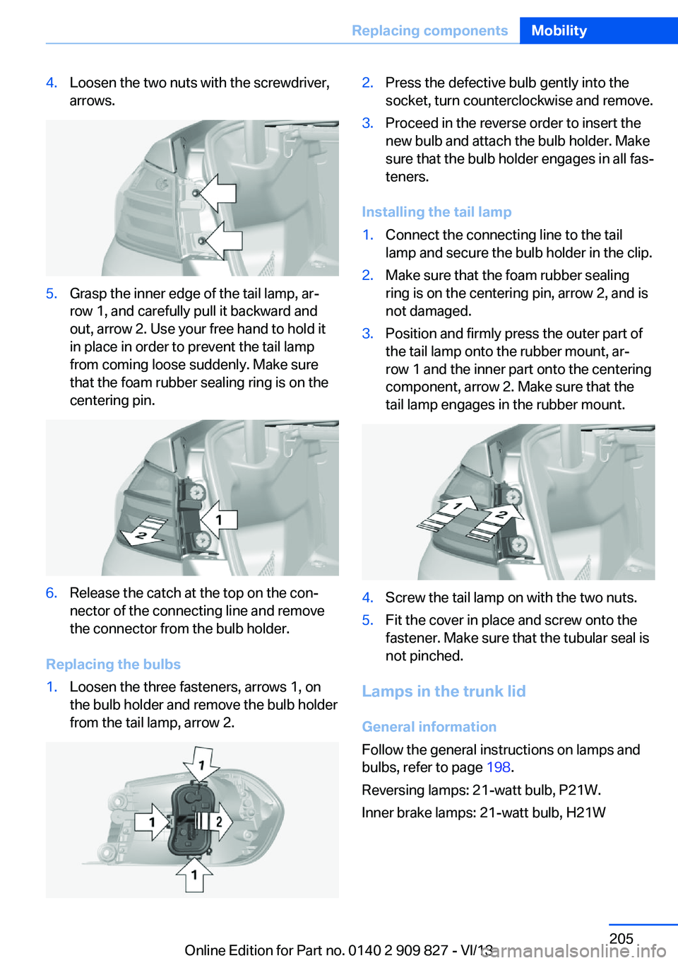
4.Loosen the two nuts with the screwdriver,
arrows.5.Grasp the inner edge of the tail lamp, ar‐
row 1, and carefully pull it backward and
out, arrow 2. Use your free hand to hold it
in place in order to prevent the tail lamp
from coming loose suddenly. Make sure
that the foam rubber sealing ring is on the
centering pin.6.Release the catch at the top on the con‐
nector of the connecting line and remove
the connector from the bulb holder.
Replacing the bulbs
1.Loosen the three fasteners, arrows 1, on
the bulb holder and remove the bulb holder
from the tail lamp, arrow 2.2.Press the defective bulb gently into the
socket, turn counterclockwise and remove.3.Proceed in the reverse order to insert the
new bulb and attach the bulb holder. Make
sure that the bulb holder engages in all fas‐
teners.
Installing the tail lamp
1.Connect the connecting line to the tail
lamp and secure the bulb holder in the clip.2.Make sure that the foam rubber sealing
ring is on the centering pin, arrow 2, and is
not damaged.3.Position and firmly press the outer part of
the tail lamp onto the rubber mount, ar‐
row 1 and the inner part onto the centering
component, arrow 2. Make sure that the
tail lamp engages in the rubber mount.4.Screw the tail lamp on with the two nuts.5.Fit the cover in place and screw onto the
fastener. Make sure that the tubular seal is
not pinched.
Lamps in the trunk lid
General information
Follow the general instructions on lamps and
bulbs, refer to page 198.
Reversing lamps: 21-watt bulb, P21W.
Inner brake lamps: 21-watt bulb, H21W
Seite 205Replacing componentsMobility205
Online Edition for Part no. 0140 2 909 827 - VI/13
Page 206 of 236
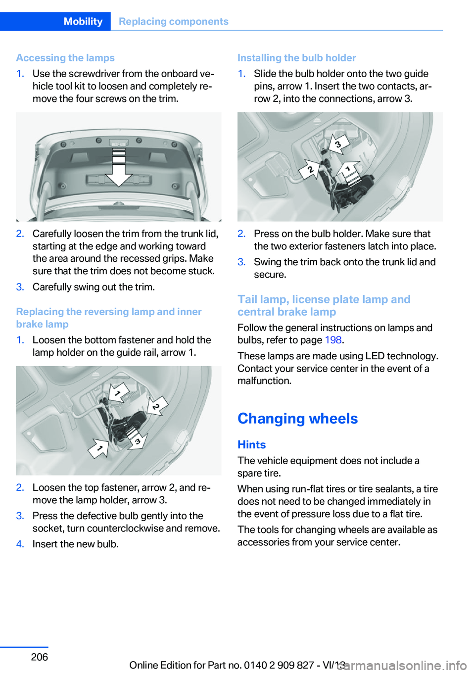
Accessing the lamps1.Use the screwdriver from the onboard ve‐
hicle tool kit to loosen and completely re‐
move the four screws on the trim.2.Carefully loosen the trim from the trunk lid,
starting at the edge and working toward
the area around the recessed grips. Make
sure that the trim does not become stuck.3.Carefully swing out the trim.
Replacing the reversing lamp and inner
brake lamp
1.Loosen the bottom fastener and hold the
lamp holder on the guide rail, arrow 1.2.Loosen the top fastener, arrow 2, and re‐
move the lamp holder, arrow 3.3.Press the defective bulb gently into the
socket, turn counterclockwise and remove.4.Insert the new bulb.Installing the bulb holder1.Slide the bulb holder onto the two guide
pins, arrow 1. Insert the two contacts, ar‐
row 2, into the connections, arrow 3.2.Press on the bulb holder. Make sure that
the two exterior fasteners latch into place.3.Swing the trim back onto the trunk lid and
secure.
Tail lamp, license plate lamp and
central brake lamp
Follow the general instructions on lamps and
bulbs, refer to page 198.
These lamps are made using LED technology.
Contact your service center in the event of a
malfunction.
Changing wheels
Hints The vehicle equipment does not include a
spare tire.
When using run-flat tires or tire sealants, a tire
does not need to be changed immediately in
the event of pressure loss due to a flat tire.
The tools for changing wheels are available as
accessories from your service center.
Seite 206MobilityReplacing components206
Online Edition for Part no. 0140 2 909 827 - VI/13
Page 208 of 236
Maintain the battery in an upright position for
transport and storage. Secure the battery so
that it does not tip over during transport.
Fuses Notes Replacing fuses
Never attempt to repair a blown fuse and
do not replace a defective fuse with a substi‐
tute of another color or amperage rating; this
could lead to a circuit overload, ultimately re‐
sulting in a fire in the vehicle.◀
Plastic tweezers and information on the fuse
types and locations are stored in the fuse box
in the cargo area.
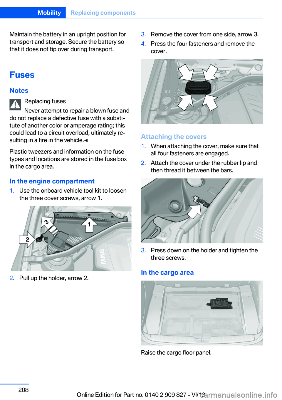
In the engine compartment1.Use the onboard vehicle tool kit to loosen
the three cover screws, arrow 1.2.Pull up the holder, arrow 2.3.Remove the cover from one side, arrow 3.4.Press the four fasteners and remove the
cover.
Attaching the covers
1.When attaching the cover, make sure that
all four fasteners are engaged.2.Attach the cover under the rubber lip and
then thread it between the bars.3.Press down on the holder and tighten the
three screws.
In the cargo area
Raise the cargo floor panel.
Seite 208MobilityReplacing components208
Online Edition for Part no. 0140 2 909 827 - VI/13
Page 214 of 236
Do not lift the vehicle
Do not lift the vehicle by the tow fitting or
body and chassis parts; otherwise, damage
may result.◀
Towing other vehicles
General information Light towing vehicle
The towing vehicle must not be lighter
than the vehicle being towed; otherwise, it will
not be possible to control the vehicle re‐
sponse.◀
Attaching the tow bar/tow rope correctly
Attach the tow bar or tow rope to the tow
fitting; connecting it to other vehicle parts may
cause damage.◀▷Switch on the hazard warning system, de‐
pending on local regulations.▷If the electrical system has failed, clearly
identify the vehicle being towed by placing
a sign or a warning triangle in the rear win‐
dow.
Tow bar
The tow fittings used should be on the same
side on both vehicles.
Should it prove impossible to avoid mounting
the tow bar at an offset angle, please observe
the following:
▷Maneuvering capability is limited during
cornering.▷The tow bar will generate lateral forces if it
is secured with an offset.
Tow rope
When starting to tow the vehicle, make sure
that the tow rope is taut.
To avoid jerking and the associated stresses
on the vehicle components when towing, al‐
ways use nylon ropes or nylon straps.
Attaching the tow rope correctly
Only secure the tow rope on the tow fit‐
ting; otherwise, damage can occur when it is
secured on other parts of the vehicle.◀
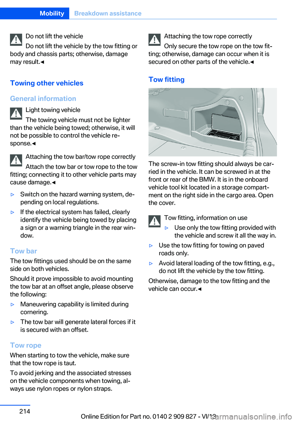
Tow fitting
The screw-in tow fitting should always be car‐
ried in the vehicle. It can be screwed in at the
front or rear of the BMW. It is in the onboard
vehicle tool kit located in a storage compart‐
ment on the right side in the cargo area. Open
the cover.
Tow fitting, information on use
▷Use only the tow fitting provided with
the vehicle and screw it all the way in.▷Use the tow fitting for towing on paved
roads only.▷Avoid lateral loading of the tow fitting, e.g.,
do not lift the vehicle by the tow fitting.
Otherwise, damage to the tow fitting and the
vehicle can occur.◀
Seite 214MobilityBreakdown assistance214
Online Edition for Part no. 0140 2 909 827 - VI/13
Page 219 of 236

Use only a mild soapy solution, with the safety
belts clipped into their buckles.
Do not allow the reels to retract the safety
belts until they are dry.
Carpets and floor mats No objects in the area around the pedals
Keep floor mats, carpets, and any other
objects out of the area of motion of the pedals;
otherwise, the function of the pedals could be
impeded while driving
Do not place additional floor mats over existing
mats or other objects.
Only use floor mats that have been approved
for the vehicle and can be properly fixed in
place.
Ensure that the floor mats are securely fas‐
tened again after they were removed for clean‐
ing, for example.◀
Floor mats can be removed from the passen‐
ger compartment for cleaning.
If the floor carpets are very dirty, clean with a
microfiber cloth and water or a textile cleaner.
To prevent matting of the carpet, rub back and
forth in the direction of travel only.
Sensors/cameras
To clean sensors and cameras, use a cloth
moistened with a small amount of glass
cleaner.
Displays/screens
Clean the displays with an antistatic microfiber
cloth.
Cleaning displays
Do not use chemical or household
cleansers.
Keep all fluids and moisture away from the
unit.
Otherwise, they could affect or damage surfa‐
ces or electrical components.Avoid pressing too hard when cleaning and do
not use abrasive materials; otherwise, damage
can result.◀
Long-term vehicle storage
Your service center can advise you on what to
consider when storing the vehicle for longer
than three months.Seite 219CareMobility219
Online Edition for Part no. 0140 2 909 827 - VI/13
Page 227 of 236
BMW maintenance sys‐tem 196
Bonus range, ECO PRO 172
Bottle holder, refer to Cu‐ pholder 159
Brake assistant 115
Brake discs, breaking in 164
Brake force display 112
Brake lamps, brake force dis‐ play 112
Brake lights, adaptive 112
Brake pads, breaking in 164
Braking, hints 165
Breakdown assis‐ tance 210, 211
Breaking in 164
Brightness of Control Dis‐ play 87
Bulb replacement 198
Bulb replacement, front 199
Bulb replacement, halogen headlamps 199
Bulb replacement, LED head‐ lamps 203
Bulb replacement, rear 204
Bulb replacement, xenon headlamps 202
Bulbs and lamps 198
Button, RES 123
Button, Start/Stop 61
Bypassing, refer to Jump- starting 211
C
California Proposition 65 Warning 7
Camera, care 219
Camera, rearview cam‐ era 131
Camera, Side View 134
Camera, Top View 135
Can holder, refer to Cu‐ pholder 159
Car battery 207
Car care products 217 Care, displays 219
Care, vehicle 217
Cargo 167
Cargo area, enlarging 155
Cargo area lid 38
Cargo area, storage compart‐ ments 160
Cargo, securing 168
Cargo straps, securing cargo 168
Car key, refer to Remote con‐ trol 32
Carpet, care 219
Car wash 216
Catalytic converter, refer to Hot exhaust system 165
CBS Condition Based Serv‐ ice 196
CD/Multimedia, see user's manual for Navigation, En‐
tertainment and Communi‐
cation
Center armrest 158
Center console 14
Center-Lock, see button for central locking 35
Central locking system 35
Central screen, refer to Con‐ trol Display 16
Changes, technical, refer to Safety 7
Changing parts 198
Changing wheels 206
Changing wheels/tires 187
Check Control 76
Checking the oil level elec‐ tronically 192
Children, seating position 57
Children, transporting safely 57
Child restraint fixing sys‐ tem 57
Child restraint fixing system LATCH 58
Child restraint fixing systems, mounting 57 Child seat, mounting 57
Child seats 57
Chrome parts, care 218
Cigarette lighter 153
Cleaning, displays 219
Climate control 142, 144
Clock 79
Closing/opening from in‐ side 38
Closing/opening via door lock 37
Closing/opening with remote control 36
Clothes hooks 160
Coasting 174
Coasting with engine decou‐ pled, coasting 174
Coasting with idling en‐ gine 174
Cockpit 12
Collision warning with City Braking function 103
Combination switch, refer to Turn signals 66
Combination switch, refer to Wiper system 66
Comfort Access 39
COMFORT program, Dy‐ namic Driving Control 118
Compartments in the doors 158
Compass 151
Computer 84
Condensation on win‐ dows 146
Condensation under the vehi‐ cle 166
Condition Based Service CBS 196
Configure driving mode 118
Confirmation signal 41
ConnectedDrive, see user's manual for Navigation, En‐
tertainment and Communi‐
cation
ConnectedDrive Services Seite 227Everything from A to ZReference227
Online Edition for Part no. 0140 2 909 827 - VI/13