2014 BMW 428I XDRIVE COUPE trunk
[x] Cancel search: trunkPage 164 of 236
Things to remember when drivingVehicle equipment
All standard, country-specific and optional
equipment that is offered in the model series is
described in this chapter. Therefore, equip‐
ment is also described that is not available in a
vehicle, e. g., because of the selected optional
equipment or country variant. This also applies
for safety-related functions and systems.
Breaking-in period General information Moving parts need to be broken in to adjust to
each other.
The following instructions will help achieve a
long vehicle life and good economy.
Engine and differential Always obey the official speed limit.
Up to 1,200 miles/2,000 km
Do not exceed the maximum engine and road
speed:▷For gasoline engine 4,500 rpm and
100 mph/160 km/h.
Avoid full load or kickdown under all circum‐
stances.
From 1,200 miles/2,000 km The engine and vehicle speed can gradually be
increased.
Tires
Due to technical factors associated with their
manufacture, tires do not achieve their full
traction potential until after an initial breaking-
in period.
Drive conservatively for the first
200 miles/300 km.
Brake system
Brakes require an initial break-in period of ap‐
prox. 300 miles/500 km to achieve optimized
contact and wear patterns between brake
discs and brake pads. Drive moderately during
this break-in period.
Clutch The function of the clutch reaches its optimal
level only after a distance driven of approx.
300 miles/500 km. During this break-in period,
engage the clutch gently.
Following part replacement
The same breaking in procedures should be
observed if any of the components mentioned
above have to be renewed in the course of the
vehicle's operating life.
General driving notes
Closing the trunk lid Drive with the trunk lid closed
Only drive with the tailgate closed; other‐
wise, in the event of an accident or braking and
evasive maneuvers, passengers and other road
users may be injured, and the vehicle may be
damaged. In addition, exhaust fumes may en‐
ter the passenger compartment.◀
If driving with the tailgate open cannot be
avoided:▷Close all windows and the glass sunroof.▷Greatly increase the blower speed.▷Drive moderately.Seite 164Driving tipsThings to remember when driving164
Online Edition for Part no. 0140 2 909 827 - VI/13
Page 167 of 236

LoadingVehicle equipment
All standard, country-specific and optional
equipment that is offered in the model series is
described in this chapter. Therefore, equip‐
ment is also described that is not available in a
vehicle, e. g., because of the selected optional
equipment or country variant. This also applies
for safety-related functions and systems.
Hints Overloading the vehicle
To avoid exceeding the approved carry‐
ing capacity of the tires, never overload the ve‐
hicle. Overloading can lead to overheating and
increases the rate at which damage develops
inside the tires. This could result in a sudden
loss of tire inflation pressure.◀
No fluids in the trunk
Make sure that fluids do not leak into the
trunk; otherwise, the vehicle may be dam‐
aged.◀
Determining the load limit1.Locate the following statement on your ve‐
hicle’s placard:▷The combined weight of occupants
and cargo should never exceed XXX kg
or YYY lbs. Otherwise, damage to thevehicle and unstable driving situations
may result.2.Determine the combined weight of the
driver and passengers that will be riding in
your vehicle.3.Subtract the combined weight of the driver
and passengers from XXX kilograms or
YYY pounds.4.The resulting figure equals the available
amount of cargo and luggage load ca‐
pacity.
For example, if the YYY amount equals
1,000 lbs and there will be four 150 lbs
passengers in your vehicle, the amount of
available cargo and luggage load capacity
is 400 lbs: 1,000 lbs minus 600 lbs =
400 lbs.5.Determine the combined weight of lug‐
gage and cargo being loaded on the vehi‐
cle. That weight may not safely exceed the
available cargo and luggage load capacity
calculated in Step 4.
Load
The maximum load is the sum of the weight of
the occupants and the cargo.
The greater the weight of the occupants, the
less cargo that can be transported.
Seite 167LoadingDriving tips167
Online Edition for Part no. 0140 2 909 827 - VI/13
Page 169 of 236
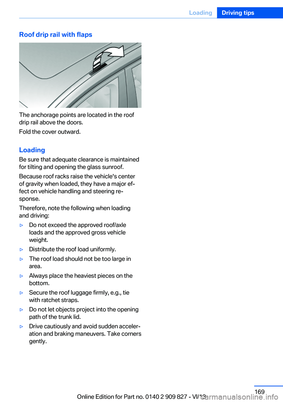
Roof drip rail with flaps
The anchorage points are located in the roof
drip rail above the doors.
Fold the cover outward.
Loading Be sure that adequate clearance is maintained
for tilting and opening the glass sunroof.
Because roof racks raise the vehicle's center
of gravity when loaded, they have a major ef‐
fect on vehicle handling and steering re‐
sponse.
Therefore, note the following when loading
and driving:
▷Do not exceed the approved roof/axle
loads and the approved gross vehicle
weight.▷Distribute the roof load uniformly.▷The roof load should not be too large in
area.▷Always place the heaviest pieces on the
bottom.▷Secure the roof luggage firmly, e.g., tie
with ratchet straps.▷Do not let objects project into the opening
path of the trunk lid.▷Drive cautiously and avoid sudden acceler‐
ation and braking maneuvers. Take corners
gently.Seite 169LoadingDriving tips169
Online Edition for Part no. 0140 2 909 827 - VI/13
Page 204 of 236
Right side of vehicle: turn counterclock‐
wise.
Remove the bulb.3.Insert the new bulb, connect the connector
and screw on the wheel house panel.
Turn signal in exterior mirror
Follow the general instructions on lamps and
bulbs, refer to page 198.
The turn signals in the exterior mirrors feature
LED technology. Contact your service center
in the event of a malfunction.
Tail lamps, bulb replacement
At a glance
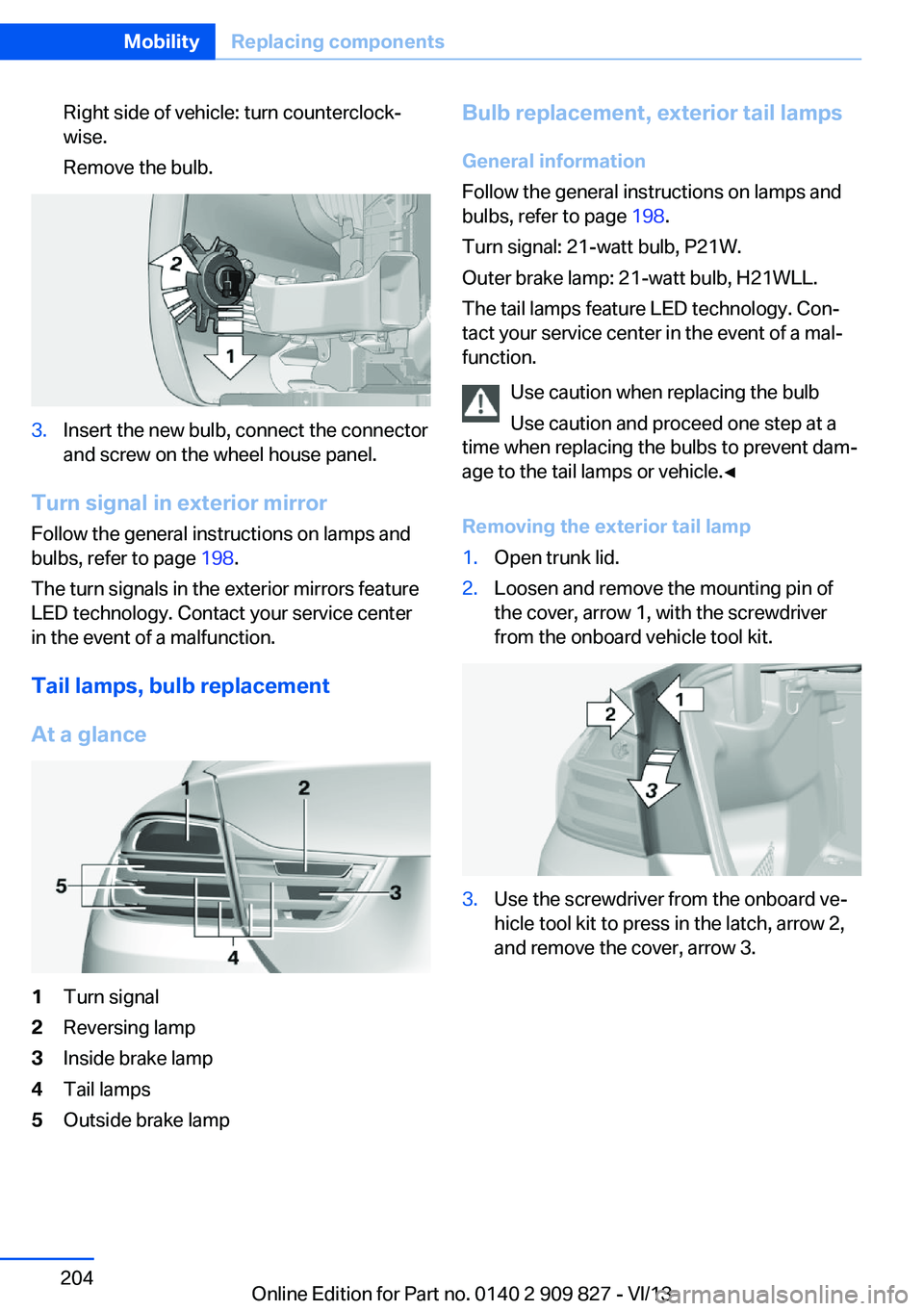
1Turn signal2Reversing lamp3Inside brake lamp4Tail lamps5Outside brake lampBulb replacement, exterior tail lamps General information
Follow the general instructions on lamps and
bulbs, refer to page 198.
Turn signal: 21-watt bulb, P21W.
Outer brake lamp: 21-watt bulb, H21WLL.
The tail lamps feature LED technology. Con‐
tact your service center in the event of a mal‐
function.
Use caution when replacing the bulb
Use caution and proceed one step at a
time when replacing the bulbs to prevent dam‐
age to the tail lamps or vehicle.◀
Removing the exterior tail lamp1.Open trunk lid.2.Loosen and remove the mounting pin of
the cover, arrow 1, with the screwdriver
from the onboard vehicle tool kit.3.Use the screwdriver from the onboard ve‐
hicle tool kit to press in the latch, arrow 2,
and remove the cover, arrow 3.Seite 204MobilityReplacing components204
Online Edition for Part no. 0140 2 909 827 - VI/13
Page 205 of 236
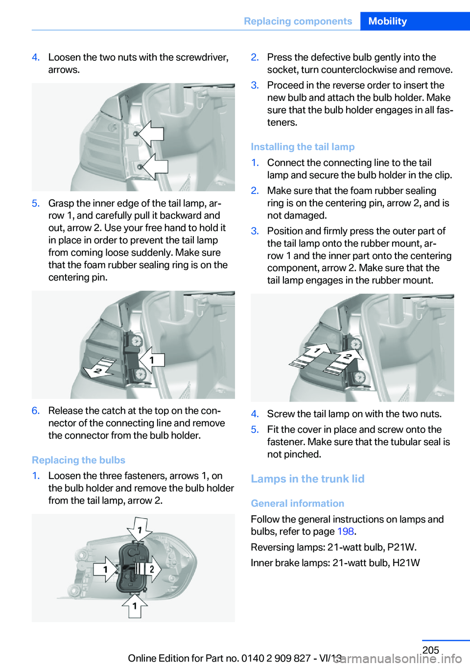
4.Loosen the two nuts with the screwdriver,
arrows.5.Grasp the inner edge of the tail lamp, ar‐
row 1, and carefully pull it backward and
out, arrow 2. Use your free hand to hold it
in place in order to prevent the tail lamp
from coming loose suddenly. Make sure
that the foam rubber sealing ring is on the
centering pin.6.Release the catch at the top on the con‐
nector of the connecting line and remove
the connector from the bulb holder.
Replacing the bulbs
1.Loosen the three fasteners, arrows 1, on
the bulb holder and remove the bulb holder
from the tail lamp, arrow 2.2.Press the defective bulb gently into the
socket, turn counterclockwise and remove.3.Proceed in the reverse order to insert the
new bulb and attach the bulb holder. Make
sure that the bulb holder engages in all fas‐
teners.
Installing the tail lamp
1.Connect the connecting line to the tail
lamp and secure the bulb holder in the clip.2.Make sure that the foam rubber sealing
ring is on the centering pin, arrow 2, and is
not damaged.3.Position and firmly press the outer part of
the tail lamp onto the rubber mount, ar‐
row 1 and the inner part onto the centering
component, arrow 2. Make sure that the
tail lamp engages in the rubber mount.4.Screw the tail lamp on with the two nuts.5.Fit the cover in place and screw onto the
fastener. Make sure that the tubular seal is
not pinched.
Lamps in the trunk lid
General information
Follow the general instructions on lamps and
bulbs, refer to page 198.
Reversing lamps: 21-watt bulb, P21W.
Inner brake lamps: 21-watt bulb, H21W
Seite 205Replacing componentsMobility205
Online Edition for Part no. 0140 2 909 827 - VI/13
Page 206 of 236
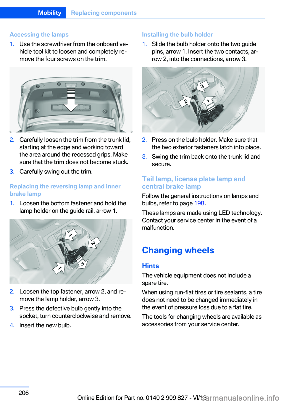
Accessing the lamps1.Use the screwdriver from the onboard ve‐
hicle tool kit to loosen and completely re‐
move the four screws on the trim.2.Carefully loosen the trim from the trunk lid,
starting at the edge and working toward
the area around the recessed grips. Make
sure that the trim does not become stuck.3.Carefully swing out the trim.
Replacing the reversing lamp and inner
brake lamp
1.Loosen the bottom fastener and hold the
lamp holder on the guide rail, arrow 1.2.Loosen the top fastener, arrow 2, and re‐
move the lamp holder, arrow 3.3.Press the defective bulb gently into the
socket, turn counterclockwise and remove.4.Insert the new bulb.Installing the bulb holder1.Slide the bulb holder onto the two guide
pins, arrow 1. Insert the two contacts, ar‐
row 2, into the connections, arrow 3.2.Press on the bulb holder. Make sure that
the two exterior fasteners latch into place.3.Swing the trim back onto the trunk lid and
secure.
Tail lamp, license plate lamp and
central brake lamp
Follow the general instructions on lamps and
bulbs, refer to page 198.
These lamps are made using LED technology.
Contact your service center in the event of a
malfunction.
Changing wheels
Hints The vehicle equipment does not include a
spare tire.
When using run-flat tires or tire sealants, a tire
does not need to be changed immediately in
the event of pressure loss due to a flat tire.
The tools for changing wheels are available as
accessories from your service center.
Seite 206MobilityReplacing components206
Online Edition for Part no. 0140 2 909 827 - VI/13
Page 211 of 236
if it can be established, are transmitted to
the BMW Response Center.▷If the LED is flashing, but the BMW Re‐
sponse Center can no longer be heard via
the speaker, you can nevertheless still be
heard for the BMW Response Center.
Initiating an Emergency Request
automatically
Under certain conditions, an Emergency Re‐
quest is automatically initiated immediately af‐
ter a severe accident. Automatic Collision Noti‐
fication is not affected by pressing the SOS
button.
Warning triangle
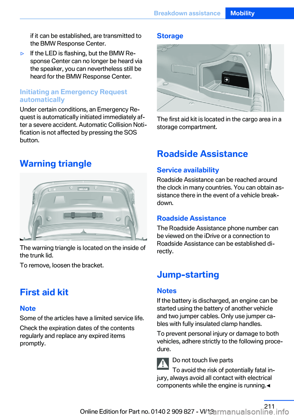
The warning triangle is located on the inside of
the trunk lid.
To remove, loosen the bracket.
First aid kit NoteSome of the articles have a limited service life.
Check the expiration dates of the contents
regularly and replace any expired items
promptly.
Storage
The first aid kit is located in the cargo area in a
storage compartment.
Roadside Assistance
Service availability
Roadside Assistance can be reached around
the clock in many countries. You can obtain as‐
sistance there in the event of a vehicle break‐
down.
Roadside Assistance The Roadside Assistance phone number can
be viewed on the iDrive or a connection to
Roadside Assistance can be established di‐
rectly.
Jump-starting
Notes If the battery is discharged, an engine can be
started using the battery of another vehicle
and two jumper cables. Only use jumper ca‐
bles with fully insulated clamp handles.
To prevent personal injury or damage to both
vehicles, adhere strictly to the following proce‐
dure.
Do not touch live parts
To avoid the risk of potentially fatal in‐
jury, always avoid all contact with electrical
components while the engine is running.◀
Seite 211Breakdown assistanceMobility211
Online Edition for Part no. 0140 2 909 827 - VI/13
Page 228 of 236

Connecting electrical devi‐ces 153
Control Display 16
Control Display, settings 86
Controller 16, 17
Control systems, driving sta‐ bility 115
Convenient opening 36
Coolant 195
Coolant temperature 79
Cooling function 143, 145
Cooling, maximum 145
Cooling system 195
Corrosion on brake discs 166
Cruise control 126
Cruise control, active with Stop & Go 120
Cruising range 79
Cupholder 159
Current fuel consumption 80
D
Damage, tires 186
Damping control, dy‐ namic 116
Data, technical 222
Date 79
Daytime running lights 90
Defrosting, refer to defrosting the windows 143
Defrosting, refer to Windows, defrosting 146
Defrosting the windows 143
Dehumidifying, air 143
Destination distance 85
Digital clock 79
Digital compass 151
Dimensions 222
Dimmable exterior mirrors 55
Dimmable interior rearview mirror 55
Direction indicator, refer to Turn signals 66
Display, electronic, instru‐ ment cluster 75 Display in windshield 140
Display lighting, refer to In‐ strument lighting 92
Displays 73
Displays, cleaning 219
Disposal, coolant 195
Disposal, vehicle battery 207
Distance control, refer to PDC 128
Distance to destination 85
Divided screen view, split screen 21
Door lock, refer to Remote control 32
Drive-off assistant 119
Drive-off assistant, refer to DSC 115
Driver assistance, see Intelli‐ gent Safety 102
Driving Assistant, see Intelli‐ gent Safety 102
Driving experience switch 117
Driving instructions, breaking in 164
Driving mode 117
Driving notes, general 164
Driving stability control sys‐ tems 115
Driving tips 164
DSC Dynamic Stability Con‐ trol 115
DTC Dynamic Traction Con‐ trol 116
Dynamic Damping Con‐ trol 116
Dynamic Stability Control DSC 115
Dynamic Traction Control DTC 116
E
ECO PRO 171
ECO PRO Analyser 175
ECO PRO, bonus range 172 ECO PRO display 171
ECO PRO driving mode 171
ECO PRO mode 171
ECO PRO Tip - driving in‐ struction 173
EfficientDynamics 173
Electronic displays, instru‐ ment cluster 75
Electronic Stability Program ESP, refer to DSC 115
Emergency detection, remote control 33
Emergency release, door lock 37
Emergency release, fuel filler flap 178
Emergency Request 210
Emergency service, refer to Roadside Assistance 211
Emergency start function, en‐ gine start 33
Emergency unlocking, trunk lid 39
Energy Control 80
Energy recovery 80
Engine, automatic Start/Stop function 63
Engine, automatic switch- off 63
Engine compartment 190
Engine compartment, work‐ ing in 191
Engine coolant 195
Engine idling when driving, coasting 174
Engine oil 192
Engine oil, adding 193
Engine oil additives 193
Engine oil change 193
Engine oil filler neck 193
Engine oil temperature 78
Engine oil types, alterna‐ tive 193
Engine oil types, ap‐ proved 193 Seite 228ReferenceEverything from A to Z228
Online Edition for Part no. 0140 2 909 827 - VI/13