2014 BMW 335I XDRIVE bumper
[x] Cancel search: bumperPage 111 of 242

Camera
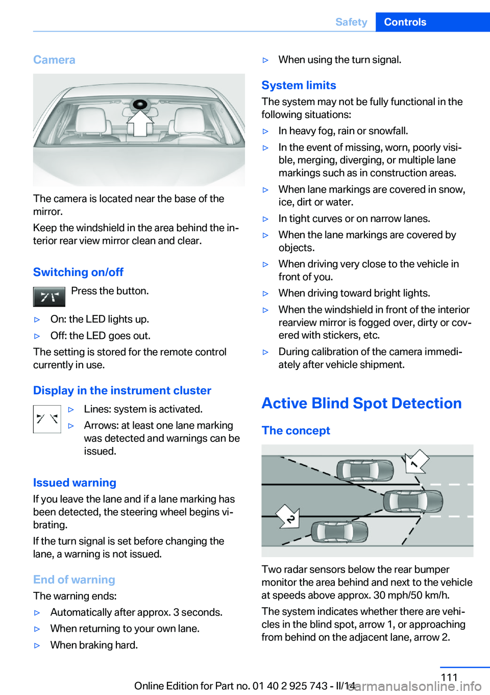
The camera is located near the base of the
mirror.
Keep the windshield in the area behind the in‐
terior rear view mirror clean and clear.
Switching on/off Press the button.
▷On: the LED lights up.▷Off: the LED goes out.
The setting is stored for the remote control
currently in use.
Display in the instrument cluster
▷Lines: system is activated.▷Arrows: at least one lane marking
was detected and warnings can be
issued.
Issued warning
If you leave the lane and if a lane marking has
been detected, the steering wheel begins vi‐
brating.
If the turn signal is set before changing the
lane, a warning is not issued.
End of warning
The warning ends:
▷Automatically after approx. 3 seconds.▷When returning to your own lane.▷When braking hard.▷When using the turn signal.
System limits
The system may not be fully functional in the
following situations:
▷In heavy fog, rain or snowfall.▷In the event of missing, worn, poorly visi‐
ble, merging, diverging, or multiple lane
markings such as in construction areas.▷When lane markings are covered in snow,
ice, dirt or water.▷In tight curves or on narrow lanes.▷When the lane markings are covered by
objects.▷When driving very close to the vehicle in
front of you.▷When driving toward bright lights.▷When the windshield in front of the interior
rearview mirror is fogged over, dirty or cov‐
ered with stickers, etc.▷During calibration of the camera immedi‐
ately after vehicle shipment.
Active Blind Spot Detection
The concept
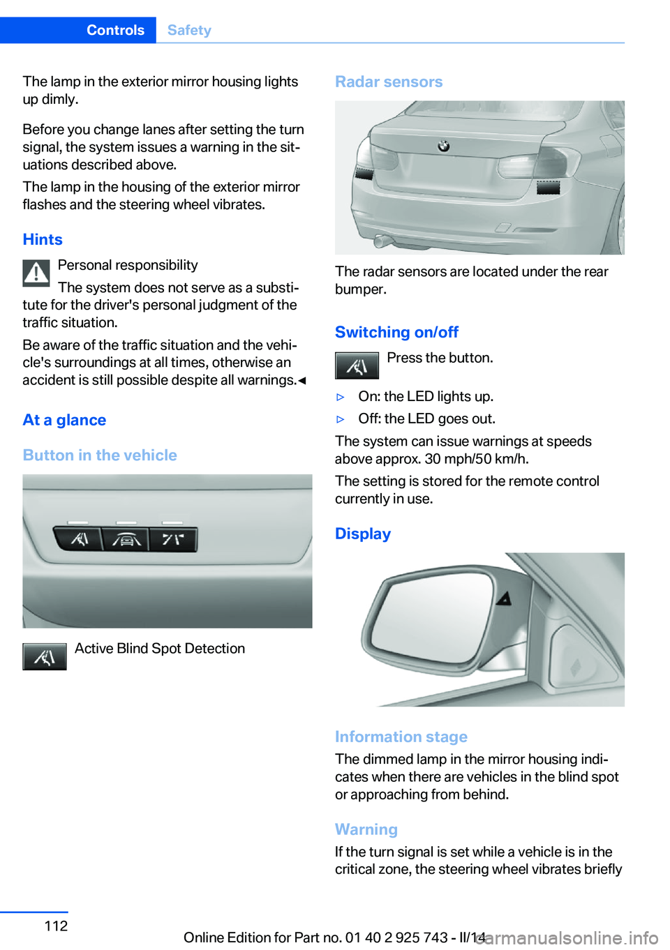
Two radar sensors below the rear bumper
monitor the area behind and next to the vehicle
at speeds above approx. 30 mph/50 km/h.
The system indicates whether there are vehi‐
cles in the blind spot, arrow 1, or approaching
from behind on the adjacent lane, arrow 2.
Seite 111SafetyControls111
Online Edition for Part no. 01 40 2 925 743 - II/14
Page 112 of 242

The lamp in the exterior mirror housing lights
up dimly.
Before you change lanes after setting the turn
signal, the system issues a warning in the sit‐
uations described above.
The lamp in the housing of the exterior mirror
flashes and the steering wheel vibrates.
Hints Personal responsibility
The system does not serve as a substi‐
tute for the driver's personal judgment of the
traffic situation.
Be aware of the traffic situation and the vehi‐
cle's surroundings at all times, otherwise an
accident is still possible despite all warnings.◀
At a glance
Button in the vehicle
Active Blind Spot Detection
Radar sensors
The radar sensors are located under the rear
bumper.
Switching on/off Press the button.
▷On: the LED lights up.▷Off: the LED goes out.
The system can issue warnings at speeds
above approx. 30 mph/50 km/h.
The setting is stored for the remote control
currently in use.
Display
Information stage
The dimmed lamp in the mirror housing indi‐
cates when there are vehicles in the blind spot
or approaching from behind.
Warning
If the turn signal is set while a vehicle is in the
critical zone, the steering wheel vibrates briefly
Seite 112ControlsSafety112
Online Edition for Part no. 01 40 2 925 743 - II/14
Page 113 of 242

and the lamp in the mirror housing flashes
brightly.
The warning stops when the turn signal is
switched off, or the other vehicle leaves the
critical zone.
System limits
The system may not be fully functional in the
following situations:▷When a vehicle is approaching at a speed
much faster than your own.▷In heavy fog, rain or snowfall.▷In tight curves or on narrow lanes.▷If the bumper is dirty or iced up, or covered
with stickers.
A Check Control message is displayed when
the system is not fully functional.
For US owners only The transmitter and receiver units comply with
part 15 of the FCC/Federal Communication
Commission regulations. Operation is gov‐
erned by the following:
FCC ID:
▷NBG009014A.
Compliance statement:
This device complies with part 15 of the FCC
Rules. Operation is subject to the following
two conditions:
▷This device may not cause harmful inter‐
ference, and▷this device must accept any interference
received, including interference that may
cause undesired operation.
Any unauthorized modifications or changes to
these devices could void the user's authority to
operate this equipment.
Brake force display
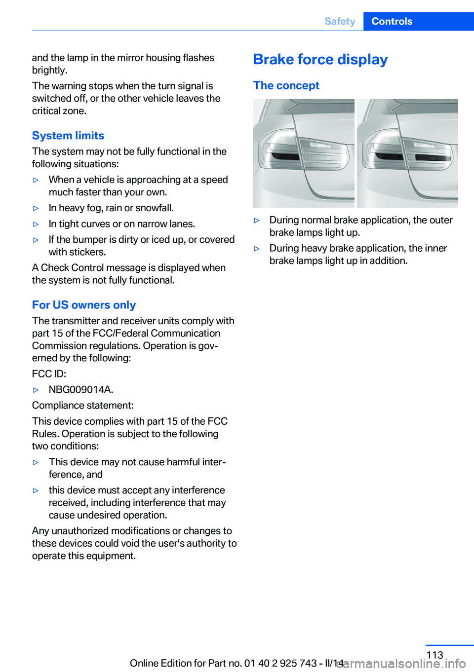
The concept▷During normal brake application, the outer
brake lamps light up.▷During heavy brake application, the inner
brake lamps light up in addition.Seite 113SafetyControls113
Online Edition for Part no. 01 40 2 925 743 - II/14
Page 120 of 242

At a glance
Buttons on the steering wheelPress the
buttonFunctionSystem on/off, interrupt, refer to
page 120Maintaining/storing the speed,
refer to page 121Resume speed, refer to
page 122Reduce distance, refer to
page 122Increase distance, refer to
page 122Rocker switch:
Maintaining/storing the speed,
refer to page 121
Changing, maintaining, and
storing the speed, refer to
page 121
The arrangement of the buttons varies accord‐
ing to the how the vehicle is equipped or coun‐
try-specific variants.
Radar sensor
A radar sensor is located in the front bumper
for detecting vehicles on the road ahead of the
vehicle.
A dirty or covered sensor may hinder the de‐
tection of vehicles.
▷If necessary, clean the radar sensor. Re‐
move layers of snow and ice carefully.▷Do not cover the view field of the radar
sensor.
Switching on/off and interrupting cruise control
Switching on Press the button on the steering
wheel.
The indicator lamps in the instrument cluster
light up and the mark in the speedometer is set
to the current speed.
Cruise control can be used.
Switching off Deactivated or interrupted system
If the system is deactivated or inter‐
rupted, actively intervene by braking, steering
and, if necessary, with evasive maneuvers; oth‐
erwise, there is the danger of an accident oc‐
curring.◀
If switching off the system while stationary,
press on the brake pedal at the same time.
Press the button.
▷If active: press twice.▷If interrupted: press once.Seite 120ControlsDriving comfort120
Online Edition for Part no. 01 40 2 925 743 - II/14
Page 128 of 242

▷The marking does not light up: the system
is switched off.
Brief status display
Selected desired speed.
If --- appears briefly on the display for Check
Control messages, it is possible that the sys‐
tem requirements for operation are currently
not met.
PDC Park Distance Control
The concept PDC support when parking. Slowly approach‐
ing an object behind or, with the appropriate
PDC equipment, also in front of your vehicle is
signaled by:
▷Signal tones.▷Visual display.
General information
Measurements are made by ultrasound sen‐
sors in the bumpers.
The range, depending on the obstacle and en‐
vironmental conditions, is approx. 6 ft/2 m.
An acoustic warning is first given:
▷By the front sensors and the two rear cor‐
ner sensors at approx. 24 in/60 cm.▷By the rear middle sensors at approx.
5 ft/1.50 m.
To ensure full operability:
▷Do not cover sensors, e.g., by stickers, bi‐
cycle racks and the like.▷Keep the sensors clean and free of ice.▷When using high-pressure washers, do not
spray the sensors for long periods and
maintain a distance of at least 12 in/30 cm.Hints
Personal responsibility
Even an active system does not relieve
the driver from personal responsibility for the
driving process.
Because of technical system limits, the system
cannot independently react appropriately in all
traffic situations.
Continuously and attentively monitor the driv‐
ing process, the area surrounding the vehicle
and the traffic situation, and actively intervene
when required, otherwise, there is a risk of an
accident.◀
Avoid driving quickly with PDC
Avoid approaching an object quickly.
Avoid driving away quickly while PDC is not yet
active.
For technical reasons, the system may other‐
wise be too late in issuing a warning.◀
At a glance
With front PDC: button in vehicle
PDC Park Distance Control
Switching on/off
Switching on automatically With the engine running, engage selector lever
position R.
Seite 128ControlsDriving comfort128
Online Edition for Part no. 01 40 2 925 743 - II/14
Page 133 of 242

System limits
Detection of objects
Very low obstacles as well as high, protruding
objects such as ledges may not be detected by
the system.
Assistance functions also take into account
data of the PDC.
Follow instructions in the PDC chapter, refer to
page 128.
The objects displayed in the Control Display
under certain circumstances are closer than
they appear. Therefore, do not estimate the
distance from the objects on the display.
Side View The concept Side View provides an early look at cross traffic
at blind driveways and intersections. Road
users concealed by obstacles to the left and
right of the vehicle can only be detected rela‐
tively late from the driver's seat. To improve
visibility, two cameras in the front of the vehi‐
cle record the traffic situation on each side.
Notes The images from both cameras are shown si‐
multaneously on the Control Display.
Check the traffic situation as well
Check the traffic situation around the ve‐
hicle on blind driveways and intersections with
your own eyes. Otherwise, an accident could
result from road users or objects located out‐
side the picture area of the Side View cam‐
eras.◀At a glance
Button in the vehicle
Side View
Cameras
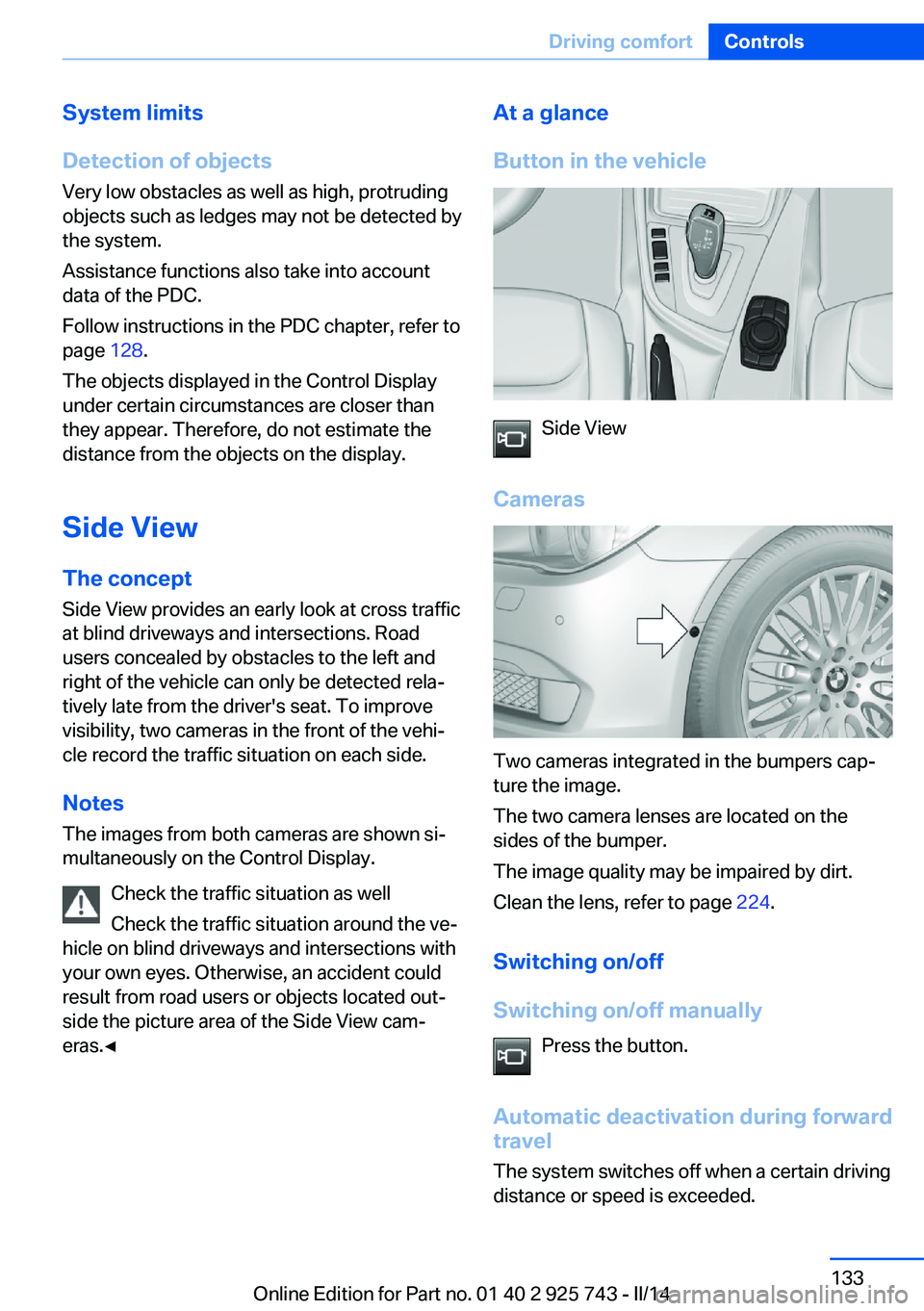
Two cameras integrated in the bumpers cap‐
ture the image.
The two camera lenses are located on the
sides of the bumper.
The image quality may be impaired by dirt.
Clean the lens, refer to page 224.
Switching on/off
Switching on/off manually Press the button.
Automatic deactivation during forward
travel
The system switches off when a certain driving
distance or speed is exceeded.
Seite 133Driving comfortControls133
Online Edition for Part no. 01 40 2 925 743 - II/14