2014 BMW 335I XDRIVE GRAN TURISMO fog light
[x] Cancel search: fog lightPage 111 of 240
Intervene immediately by braking or making an
evasive maneuver.
Braking intervention The warning prompts the driver himself to in‐
tervene. During the warning, the maximum
braking force is used, even with light pressure
on the brake pedal. In addition, if there is a risk
of collision, the system can assist with a slight
braking intervention. The intervention can bring a vehicle traveling at slow speed to a
complete stop.
Manual transmission: During a braking inter‐
vention up until reaching a complete stop, the
engine may be shut down.
The braking intervention is executed only if
DSC Dynamic Stability Control is switched on
and Dynamic Traction Control DTC is acti‐
vated.
The braking intervention can be interrupted by
pressing on the accelerator or by actively mov‐
ing the steering wheel.
When towing or tow-starting the vehicle,
switch off the pedestrian warning to prevent
undesired interventions.
System limits Be alert
Due to system limitations, warnings may
be not be issued at all, or may be issued late or
improperly. Therefore, always be alert and
ready to intervene; otherwise, there is the dan‐
ger of an accident occurring.◀
Detection range
The detection capability of the camera is lim‐
ited.
This may result in the warning not being is‐
sued or being issued late.
For example, the following situations may not
be detected:▷Partially covered pedestrians.▷Pedestrians that are not detected as such
because of the viewing angle or contour.▷Pedestrians outside of the detection range.▷Pedestrians below a body size of approx.
32 in/80 cm.
Functional limitations
The system may not be fully functional or may
not be available in the following situations:
▷In heavy fog, rain, sprayed water or snow‐
fall.▷In tight curves.▷If the camera view field or the front wind‐
shield are dirty or covered.▷When driving toward bright lights.▷Up to 10 seconds after the start of the en‐
gine, via the Start/Stop knob.▷During calibration of the camera immedi‐
ately after vehicle shipment.
Lane departure warning
The concept Starting at a specific speed, this system alerts
you when the vehicle on streets with lane
markings is about to leave the lane. Depending
on the country-specific version of the vehicle,
the speed is between 35 mph/55 km/h and
45 mph/70 km/h. If the system is switched on
below this speed, a message appears in the in‐
strument cluster.
The steering wheel begins vibrating gently in
the event of warnings. The time of the warning
may vary depending on the current driving sit‐
uation.
The system does not provide a warning if the
turn signal is set before leaving the lane.
Seite 111SafetyControls111
Online Edition for Part no. 0140 2 920 413 - VI/13
Page 112 of 240
NotesPersonal responsibility
The system cannot serve as a substitute
for the driver's personal judgment of the
course of the road and the traffic situation.
In the event of a warning, do not jerk the steer‐
ing wheel, as you may lose control of the vehi‐
cle.◀
At a glance
Button in the vehicle
Lane departure warning
Camera
The camera is located near the base of the
mirror.
Keep the windshield in the area behind the in‐
terior rear view mirror clean and clear.
Switching on/off Press the button.
▷On: the LED lights up.▷Off: the LED goes out.
The state is stored for the remote control cur‐
rently in use.
Display in the instrument cluster
▷Lines: system is activated.▷Arrows: at least one lane marking
was detected and warnings can be
issued.
Issued warning
If you leave the lane and if a lane marking has
been detected, the steering wheel begins vi‐
brating.
If the turn signal is set before changing the
lane, a warning is not issued.
End of warning
The warning ends:
▷Automatically after approx. 3 seconds.▷When returning to your own lane.▷When braking hard.▷When using the turn signal.
System limits
The system may not be fully functional in the
following situations:
▷In heavy fog, rain or snowfall.▷In the event of worn, poorly visible, merg‐
ing, diverging, or multiple lane markings
such as in construction areas.▷When lane markings are covered in snow,
ice, dirt or water.▷In tight curves or on narrow lanes.▷When the lane markings are covered by
objects.▷When driving very close to the vehicle in
front of you.▷When driving toward bright lights.Seite 112ControlsSafety112
Online Edition for Part no. 0140 2 920 413 - VI/13
Page 113 of 240
▷When the windshield in front of the interior
rearview mirror is fogged over, dirty or cov‐
ered with stickers, etc.▷During calibration of the camera immedi‐
ately after vehicle shipment.
Active Blind Spot Detection
The concept
Two radar sensors below the rear bumper
monitor the area behind and next to the vehicle
at speeds above approx. 30 mph/50 km/h.
The system indicates whether there are vehi‐
cles in the blind spot, arrow 1, or approaching
from behind on the adjacent lane, arrow 2.
The lamp in the exterior mirror housing lights
up dimly.
Before you change lanes after setting the turn
signal, the system issues a warning in the sit‐
uations described above.
The lamp in the housing of the exterior mirror
flashes and the steering wheel vibrates.
Notes Personal responsibility
The system does not serve as a substi‐
tute for the driver's personal judgment of the
traffic situation.
Be aware of the traffic situation and the vehi‐
cle's surroundings at all times, otherwise an
accident is still possible despite all warnings.◀
At a glance
Button in the vehicle
Active Blind Spot Detection
Radar sensors
The radar sensors are located under the rear
bumper.
Switching on/off Press the button.
▷On: the LED lights up.▷Off: the LED goes out.
The system can issue warnings at speeds
above approx. 30 mph/50 km/h
The state is stored for the remote control cur‐
rently in use.
Seite 113SafetyControls113
Online Edition for Part no. 0140 2 920 413 - VI/13
Page 114 of 240
Display
Information stage
The dimmed lamp in the mirror housing indi‐
cates when there are vehicles in the blind spot
or approaching from behind.
Warning
If the turn signal is set while a vehicle is in the
critical zone, the steering wheel vibrates briefly
and the lamp in the mirror housing flashes
brightly.
The warning stops when the turn signal is
switched off, or the other vehicle leaves the
critical zone.
System limits
The system may not be fully functional in the
following situations:
▷When a vehicle is approaching at a speed
much faster than your own.▷In heavy fog, rain or snowfall.▷In tight curves or on narrow lanes.▷If the bumper is dirty or iced up, or covered
with stickers.
A Check Control message is displayed when
the system is not fully functional.
For US owners only The transmitter and receiver units comply with
part 15 of the FCC/Federal Communication
Commission regulations. Operation is gov‐
erned by the following:
FCC ID:
▷NBG009014A.
Compliance statement:
This device complies with part 15 of the FCC
Rules. Operation is subject to the following
two conditions:
▷This device may not cause harmful inter‐
ference, and▷this device must accept any interference
received, including interference that may
cause undesired operation.
Any unauthorized modifications or changes to
these devices could void the user's authority to
operate this equipment.
Brake force display
The concept
▷During normal brake application, the outer
brake lamps light up.▷During heavy brake application, the inner
brake lamps light up in addition.
Active Protection
General information
The Active Protection safety package consists
of systems that are independent of each other:
▷Attentiveness assistant.▷PreCrash▷PostCrashSeite 114ControlsSafety114
Online Edition for Part no. 0140 2 920 413 - VI/13
Page 124 of 240
The arrangement of the buttons varies accord‐
ing to the how the vehicle is equipped or coun‐
try-specific variants.
Radar sensor
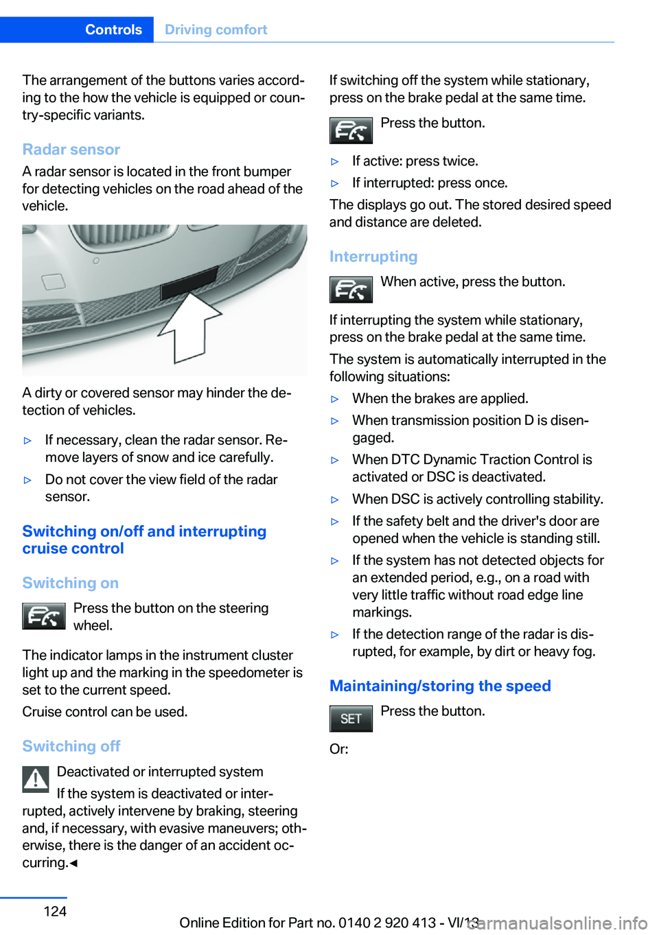
A radar sensor is located in the front bumper
for detecting vehicles on the road ahead of the
vehicle.
A dirty or covered sensor may hinder the de‐
tection of vehicles.
▷If necessary, clean the radar sensor. Re‐
move layers of snow and ice carefully.▷Do not cover the view field of the radar
sensor.
Switching on/off and interrupting cruise control
Switching on Press the button on the steering
wheel.
The indicator lamps in the instrument cluster
light up and the marking in the speedometer is
set to the current speed.
Cruise control can be used.
Switching off Deactivated or interrupted system
If the system is deactivated or inter‐
rupted, actively intervene by braking, steering
and, if necessary, with evasive maneuvers; oth‐
erwise, there is the danger of an accident oc‐
curring.◀
If switching off the system while stationary,
press on the brake pedal at the same time.
Press the button.▷If active: press twice.▷If interrupted: press once.
The displays go out. The stored desired speed
and distance are deleted.
Interrupting When active, press the button.
If interrupting the system while stationary,
press on the brake pedal at the same time.
The system is automatically interrupted in the
following situations:
▷When the brakes are applied.▷When transmission position D is disen‐
gaged.▷When DTC Dynamic Traction Control is
activated or DSC is deactivated.▷When DSC is actively controlling stability.▷If the safety belt and the driver's door are
opened when the vehicle is standing still.▷If the system has not detected objects for
an extended period, e.g., on a road with
very little traffic without road edge line
markings.▷If the detection range of the radar is dis‐
rupted, for example, by dirt or heavy fog.
Maintaining/storing the speed
Press the button.
Or:
Seite 124ControlsDriving comfort124
Online Edition for Part no. 0140 2 920 413 - VI/13
Page 207 of 240
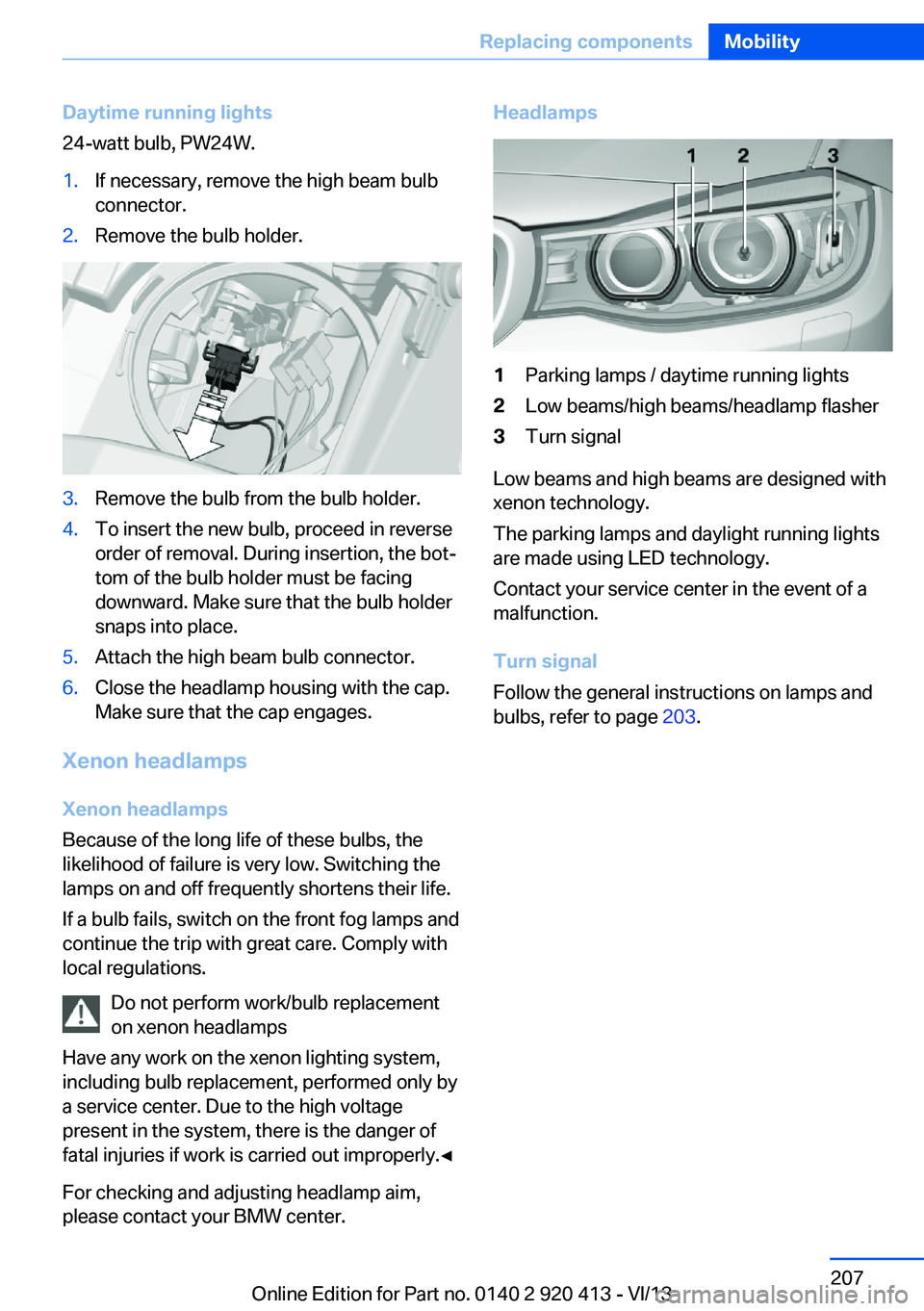
Daytime running lights
24-watt bulb, PW24W.1.If necessary, remove the high beam bulb
connector.2.Remove the bulb holder.3.Remove the bulb from the bulb holder.4.To insert the new bulb, proceed in reverse
order of removal. During insertion, the bot‐
tom of the bulb holder must be facing
downward. Make sure that the bulb holder
snaps into place.5.Attach the high beam bulb connector.6.Close the headlamp housing with the cap.
Make sure that the cap engages.
Xenon headlamps
Xenon headlamps
Because of the long life of these bulbs, the
likelihood of failure is very low. Switching the
lamps on and off frequently shortens their life.
If a bulb fails, switch on the front fog lamps and
continue the trip with great care. Comply with
local regulations.
Do not perform work/bulb replacement
on xenon headlamps
Have any work on the xenon lighting system,
including bulb replacement, performed only by
a service center. Due to the high voltage
present in the system, there is the danger of
fatal injuries if work is carried out improperly.◀
For checking and adjusting headlamp aim,
please contact your BMW center.
Headlamps1Parking lamps / daytime running lights2Low beams/high beams/headlamp flasher3Turn signal
Low beams and high beams are designed with
xenon technology.
The parking lamps and daylight running lights
are made using LED technology.
Contact your service center in the event of a
malfunction.
Turn signal
Follow the general instructions on lamps and
bulbs, refer to page 203.
Seite 207Replacing componentsMobility207
Online Edition for Part no. 0140 2 920 413 - VI/13
Page 208 of 240
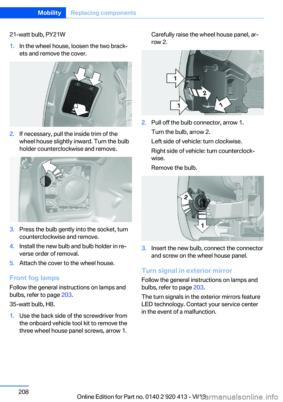
21-watt bulb, PY21W1.In the wheel house, loosen the two brack‐
ets and remove the cover.2.If necessary, pull the inside trim of the
wheel house slightly inward. Turn the bulb
holder counterclockwise and remove.3.Press the bulb gently into the socket, turn
counterclockwise and remove.4.Install the new bulb and bulb holder in re‐
verse order of removal.5.Attach the cover to the wheel house.
Front fog lamps
Follow the general instructions on lamps and
bulbs, refer to page 203.
35-watt bulb, H8.
1.Use the back side of the screwdriver from
the onboard vehicle tool kit to remove the
three wheel house panel screws, arrow 1.Carefully raise the wheel house panel, ar‐
row 2.2.Pull off the bulb connector, arrow 1.
Turn the bulb, arrow 2.
Left side of vehicle: turn clockwise.
Right side of vehicle: turn counterclock‐
wise.
Remove the bulb.3.Insert the new bulb, connect the connector
and screw on the wheel house panel.
Turn signal in exterior mirror
Follow the general instructions on lamps and
bulbs, refer to page 203.
The turn signals in the exterior mirrors feature
LED technology. Contact your service center
in the event of a malfunction.
Seite 208MobilityReplacing components208
Online Edition for Part no. 0140 2 920 413 - VI/13