2014 BMW 335I light
[x] Cancel search: lightPage 130 of 242
Low objects already displayed, e.g., curbs, can
move into the blind area of the sensors before
or after a continuous tone sounds.
False warnings
PDC may issue a warning under the following conditions even though there is no obstacle
within the detection range:▷In heavy rain.▷When sensors are very dirty or covered in
ice.▷When sensors are covered in snow.▷On rough road surfaces.▷On uneven surfaces, such as speed
bumps.▷In large buildings with right angles and
smooth walls, e.g., in underground ga‐
rages.▷In heavy exhaust.▷Due to other ultrasound sources, e.g.,
sweeping machines, high pressure steam
cleaners or neon lights.
The malfunction is signaled by a continu‐
ous tone alternating between the front and
rear speakers. As soon as the malfunction
due to other ultrasound sources is no lon‐
ger present, the system is again fully func‐
tional.
Malfunction
A Check Control message is displayed.
The range of the sensors is shown as a shaded
area on the Control Display.
PDC has failed. Have the system checked.
To ensure full operability:
▷Keep the sensors clean and free of ice.▷Do not adhere any stickers to the sensors.▷When using high-pressure washers, do not
spray the sensors for long periods and
maintain a distance of at least 12 in/30 cm.Surround View
The concept Surround View comprises various camera as‐
sistance systems that help the driver when
parking, maneuvering, and at complex exits
and intersections.▷Rearview camera, refer to page 130▷Side View, refer to page 133.▷Top View, refer to page 134.
Rearview camera
The concept The rearview camera provides assistance in
parking and maneuvering backwards. The area
behind the vehicle is shown on the Control
Display.
Hints Check the traffic situation as well
Check the traffic situation around the ve‐
hicle with your own eyes. Otherwise, an acci‐
dent could result from road users or objects lo‐
cated outside the picture area of the backup
camera.◀
At a glance
Button in the vehicle
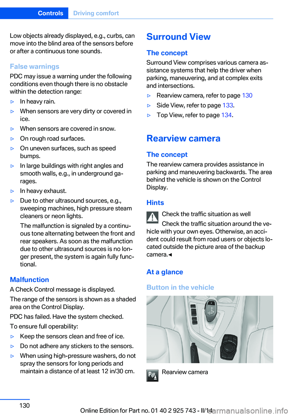
Rearview camera
Seite 130ControlsDriving comfort130
Online Edition for Part no. 01 40 2 925 743 - II/14
Page 131 of 242
Camera
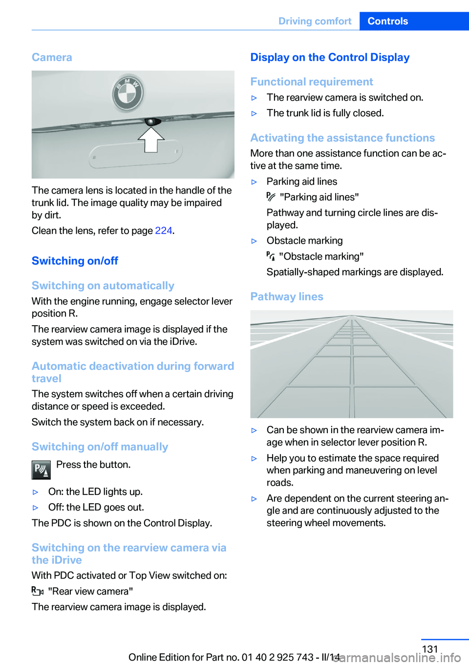
The camera lens is located in the handle of the
trunk lid. The image quality may be impaired
by dirt.
Clean the lens, refer to page 224.
Switching on/off
Switching on automatically With the engine running, engage selector lever
position R.
The rearview camera image is displayed if the
system was switched on via the iDrive.
Automatic deactivation during forward
travel
The system switches off when a certain driving
distance or speed is exceeded.
Switch the system back on if necessary.
Switching on/off manually Press the button.
▷On: the LED lights up.▷Off: the LED goes out.
The PDC is shown on the Control Display.
Switching on the rearview camera via
the iDrive
With PDC activated or Top View switched on:
"Rear view camera"
The rearview camera image is displayed.
Display on the Control Display
Functional requirement▷The rearview camera is switched on.▷The trunk lid is fully closed.
Activating the assistance functions
More than one assistance function can be ac‐
tive at the same time.
▷Parking aid lines
"Parking aid lines"
Pathway and turning circle lines are dis‐
played.
▷Obstacle marking
"Obstacle marking"
Spatially-shaped markings are displayed.
Pathway lines
▷Can be shown in the rearview camera im‐
age when in selector lever position R.▷Help you to estimate the space required
when parking and maneuvering on level
roads.▷Are dependent on the current steering an‐
gle and are continuously adjusted to the
steering wheel movements.Seite 131Driving comfortControls131
Online Edition for Part no. 01 40 2 925 743 - II/14
Page 135 of 242

Cameras
The lenses of the Top View cameras are lo‐
cated at the bottom of the exterior mirror hous‐
ings. The image quality may be impaired by
dirt.
Clean the lens, refer to page 224.
Switching on/off
Switching on automatically With the engine running, engage selector lever
position R.
The Top View and PDC images are displayed if
the system is switched on via iDrive.
Automatic deactivation during forward
travel
The system switches off when a certain driving
distance or speed is exceeded.
Switch the system back on if necessary.
Switching on/off manually Press the button.
▷On: the LED lights up.▷Off: the LED goes out.
Top View is displayed.
Display
Visual warning
The approach of the vehicle to an object can
be shown on the Control Display.
When the distance to an object is small, a red
bar is shown in front of the vehicle, as it is in
the PDC display.
The display appears as soon as Top View is
activated.
When the image of the rearview camera is dis‐
played, it is possible to switch to top view:
"Rear view camera"
Brightness With Top View switched on:
1. Select the symbol.2.Turn the controller until the desired setting
is reached, and press the controller.
Contrast
With Top View switched on:
1. Select the symbol.2.Turn the controller until the desired setting
is reached, and press the controller.
Displaying the turning circle and
pathway lines
▷The static, red turning circle line shows the
space needed to the side of the vehicle
when the steering wheel is turned all the
way.▷The variable, green pathway line assists
you in assessing the amount of space ac‐
tually needed to the side of the vehicle.
The lane line depends on the engaged
gear and the current steering angle. TheSeite 135Driving comfortControls135
Online Edition for Part no. 01 40 2 925 743 - II/14
Page 136 of 242

track line is continuously adjusted for the
steering wheel movement.
"Parking aid lines"
Turning circle and pathway lines are displayed.
System limits
Top View cannot be used in the following sit‐
uations:
▷With a door open.▷With the trunk lid open.▷With an exterior mirror folded in.▷In poor light.
A Check Control message is displayed in some
of these situations.
Parking assistant The concept
This system assists the driver in parking paral‐
lel to the road.
Ultrasound sensors measure parking spaces
on both sides of the vehicle.
The parking assistant calculates the best pos‐
sible parking line and takes control of steering
during the parking procedure.
When parking, also take note of the visual and
acoustic information and instructions issued
by the PDC, the parking assistant and the rear‐
view camera and react accordingly.
A component of the parking assistant is the
PDC Park Distance Control, refer to page 128.
Hints
Personal responsibility
Even an active system does not relieve
the driver from personal responsibility for the
driving process.
Because of technical system limits, the system
cannot independently react appropriately in all
traffic situations.
Continuously and attentively monitor the driv‐
ing process, the area surrounding the vehicle
and the traffic situation, and actively intervene
when required, otherwise, there is a risk of an
accident.◀
Changes to the parking space
Changes to the parking space after it was
measured are not taken into account by the system.
Therefore, always be alert and ready to inter‐
vene; otherwise, there is the danger of an acci‐
dent occurring.◀
Transporting loads
Loads that extend beyond the perimeter
of the vehicle are not taken into account by the
system during the parking procedure.
Therefore, always be alert and ready to inter‐
vene; otherwise, there is the danger of an acci‐
dent occurring.◀
Curbs
The parking assistant may steer the vehi‐
cle over or onto curbs.
Therefore, always be alert and ready to inter‐
vene; otherwise, the wheels, tires, or the vehi‐
cle may become damaged.◀
An engine that has been switched off by the
Auto Start Stop function is restarted automati‐
cally when the parking assistant is activated.Seite 136ControlsDriving comfort136
Online Edition for Part no. 01 40 2 925 743 - II/14
Page 137 of 242
Requirements
For measuring parking spaces▷Maximum speed while driving forward ap‐
prox. 22 mph/35 km/h.▷Maximum distance to row of parked vehi‐
cles: 5 ft/1.5 m.
Suitable parking space
▷Gap between two objects with a minimum
length of approx. 5 ft/1.5 m.▷Min. length of gap between two objects:
your vehicle's length plus approx.
4 ft/1.2 m.▷Minimum depth: approx. 5 ft/1.5 m.
For parking procedure
▷Doors and trunk lid closed.▷Parking brake released.▷When parking in parking spaces on the
driver's side, the corresponding turn signal
must be set where applicable.
At a glance
Button in the vehicle
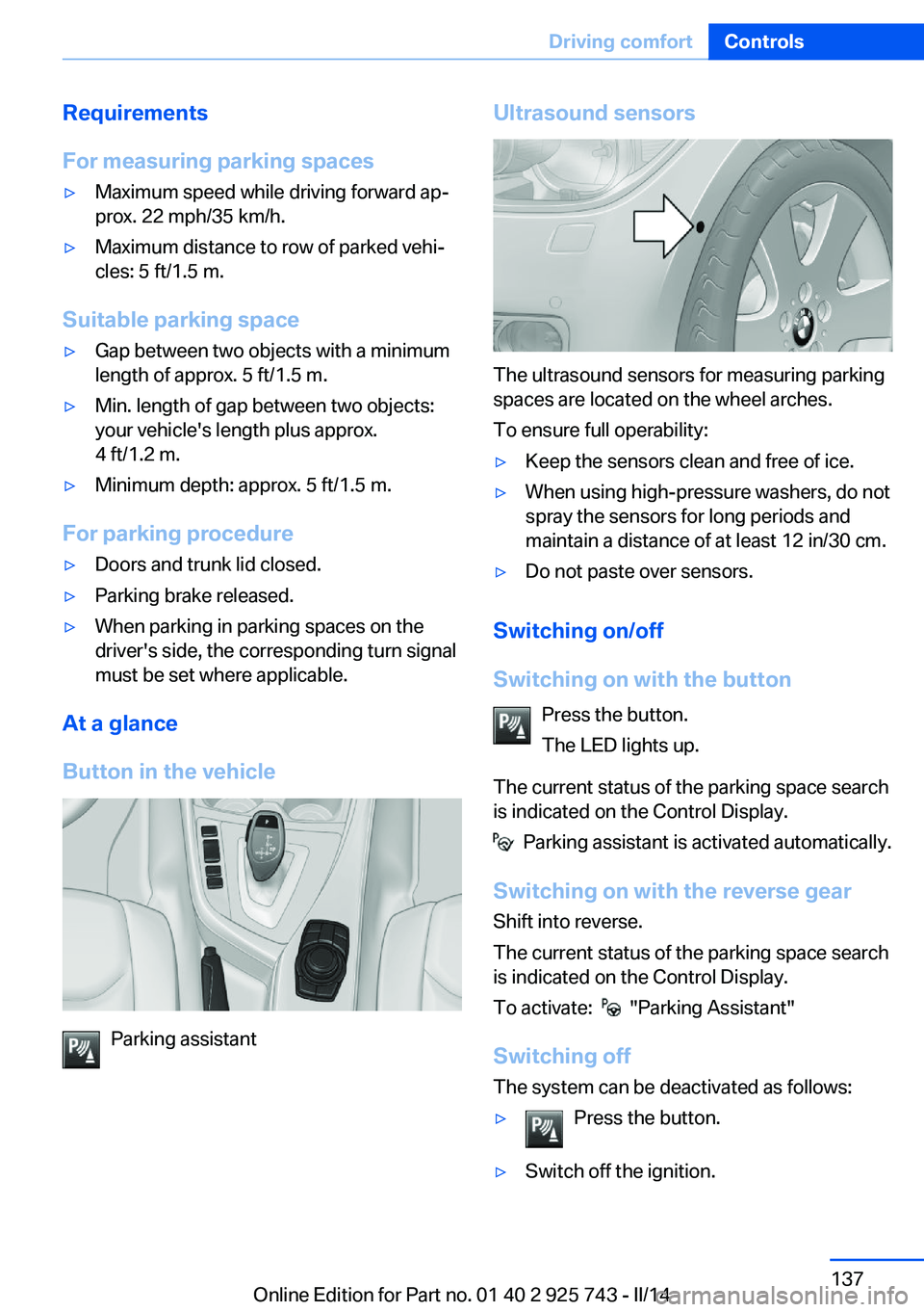
Parking assistant
Ultrasound sensors
The ultrasound sensors for measuring parking
spaces are located on the wheel arches.
To ensure full operability:
▷Keep the sensors clean and free of ice.▷When using high-pressure washers, do not
spray the sensors for long periods and
maintain a distance of at least 12 in/30 cm.▷Do not paste over sensors.
Switching on/off
Switching on with the button Press the button.
The LED lights up.
The current status of the parking space search
is indicated on the Control Display.
Parking assistant is activated automatically.
Switching on with the reverse gear
Shift into reverse.
The current status of the parking space search
is indicated on the Control Display.
To activate:
"Parking Assistant"
Switching off The system can be deactivated as follows:
▷Press the button.▷Switch off the ignition.Seite 137Driving comfortControls137
Online Edition for Part no. 01 40 2 925 743 - II/14
Page 138 of 242
Display on the Control Display
System activated/deactivatedSymbolMeaning Gray: the system is not available.
White: the system is available but
not activated. The system is activated.
Status display
Depending on the appointment version, differ‐
ent views of the status display are shown and
are described below as View 1, refer to
page 138, or View 2, refer to page 138.
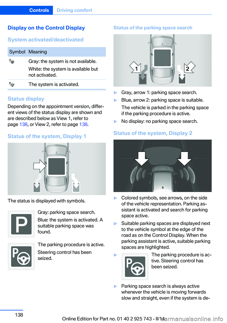
Status of the system, Display 1
The status is displayed with symbols. Gray: parking space search.
Blue: the system is activated. A
suitable parking space was
found.
The parking procedure is active. Steering control has been
seized.
Status of the parking space search▷Gray, arrow 1: parking space search.▷Blue, arrow 2: parking space is suitable.
The vehicle is parked in the parking space
if the parking procedure is active.▷No display: no parking space search.
Status of the system, Display 2
▷Colored symbols, see arrows, on the side
of the vehicle representation. Parking as‐
sistant is activated and search for parking
space active.▷Suitable parking spaces are displayed next
to the vehicle symbol at the edge of the
road as on the Control Display. When the
parking assistant is active, suitable parking
spaces are highlighted.▷The parking procedure is ac‐
tive. Steering control has
been seized.▷Parking space search is always active
whenever the vehicle is moving forwards
slow and straight, even if the system is de‐Seite 138ControlsDriving comfort138
Online Edition for Part no. 01 40 2 925 743 - II/14
Page 147 of 242
Toward red: warmer.
Adjusting the ventilation
▷Ventilation for cooling:
Adjust the vent to direct the air in your di‐
rection, such as if the vehicle interior is hot
from the sun.▷Draft-free ventilation:
Adjust the vent to let the air flow past you.
Ventilation in the rear
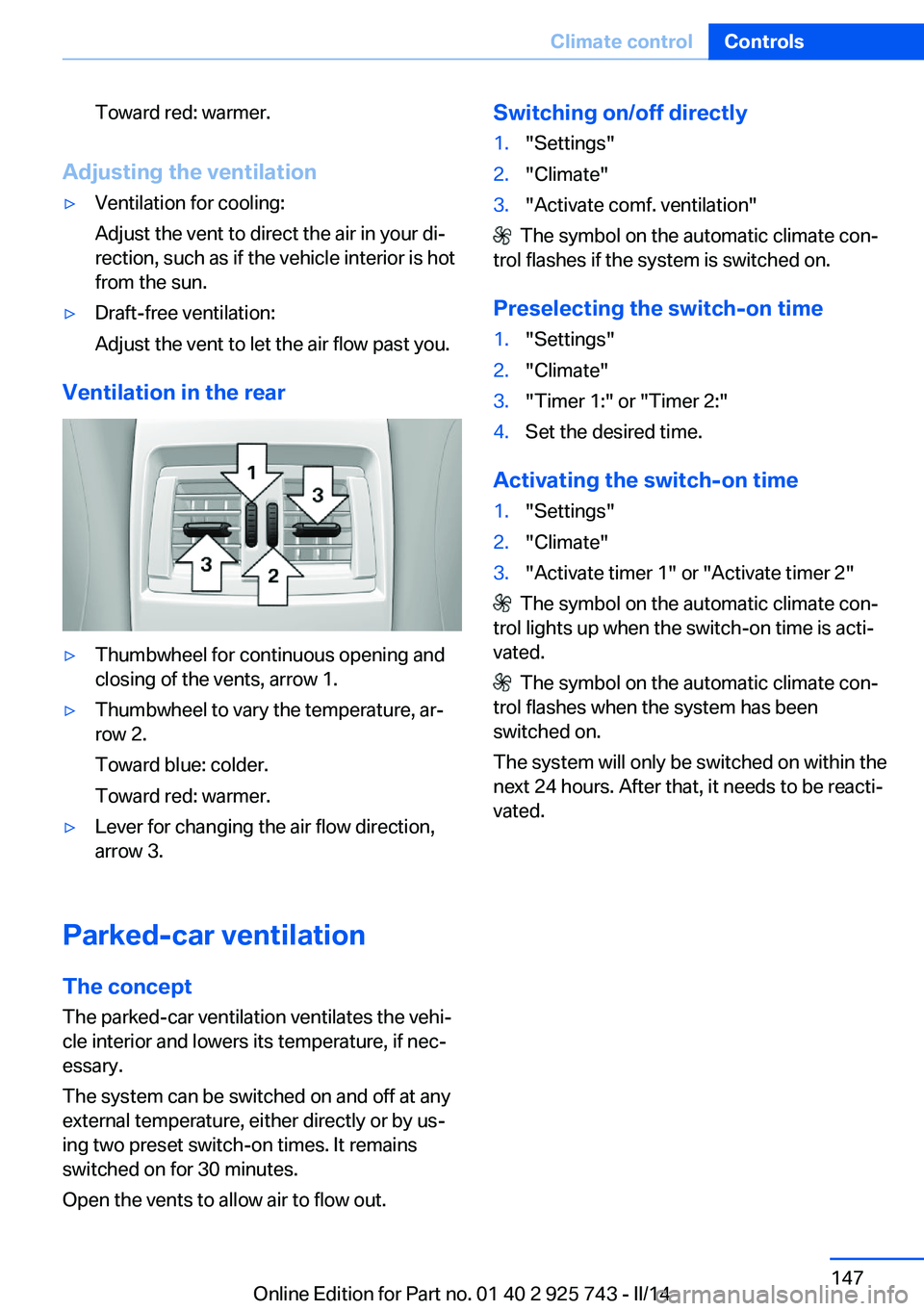
▷Thumbwheel for continuous opening and
closing of the vents, arrow 1.▷Thumbwheel to vary the temperature, ar‐
row 2.
Toward blue: colder.
Toward red: warmer.▷Lever for changing the air flow direction,
arrow 3.
Parked-car ventilation
The concept The parked-car ventilation ventilates the vehi‐
cle interior and lowers its temperature, if nec‐
essary.
The system can be switched on and off at any
external temperature, either directly or by us‐
ing two preset switch-on times. It remains
switched on for 30 minutes.
Open the vents to allow air to flow out.
Switching on/off directly1."Settings"2."Climate"3."Activate comf. ventilation"
The symbol on the automatic climate con‐
trol flashes if the system is switched on.
Preselecting the switch-on time
1."Settings"2."Climate"3."Timer 1:" or "Timer 2:"4.Set the desired time.
Activating the switch-on time
1."Settings"2."Climate"3."Activate timer 1" or "Activate timer 2"
The symbol on the automatic climate con‐
trol lights up when the switch-on time is acti‐
vated.
The symbol on the automatic climate con‐
trol flashes when the system has been
switched on.
The system will only be switched on within the
next 24 hours. After that, it needs to be reacti‐
vated.
Seite 147Climate controlControls147
Online Edition for Part no. 01 40 2 925 743 - II/14
Page 148 of 242
Interior equipmentVehicle equipmentAll standard, country-specific and optional
equipment that is offered in the model series is
described in this chapter. Therefore, equip‐
ment is also described that is not available in a
vehicle, e. g., because of the selected optional
equipment or country variant. This also applies
for safety-related functions and systems.
Universal garage door
opener
The concept
The universal garage door opener can operate
up to 3 functions of remote-controlled sys‐
tems such as garage door drives or lighting
systems. The universal garage door opener re‐
places up to 3 different hand-held transmitters.
To operate the remote control, the buttons on
the interior rearview mirror must be program‐
med with the desired functions. The hand-held
transmitter for the particular system is required
in order to program the remote control.
During programming
During programming and before activat‐
ing a device using the integrated universal re‐
mote control, ensure that there are no people,
animals, or objects in the range of movement
of the remote-controlled device; otherwise,
there is a risk of injury or damage.
Also follow the safety instructions of the hand-
held transmitter.◀
Before selling the vehicle, delete the stored
functions for the sake of security.
Compatibility If this symbol is printed on the packag‐
ing or in the instructions of the system
to be controlled, the system is gener‐ally compatible with the universal garage door
opener.
If you have any questions, please contact:▷Your service center.▷www.homelink.com on the Internet.
HomeLink is a registered trademark of John‐
son Controls, Inc.
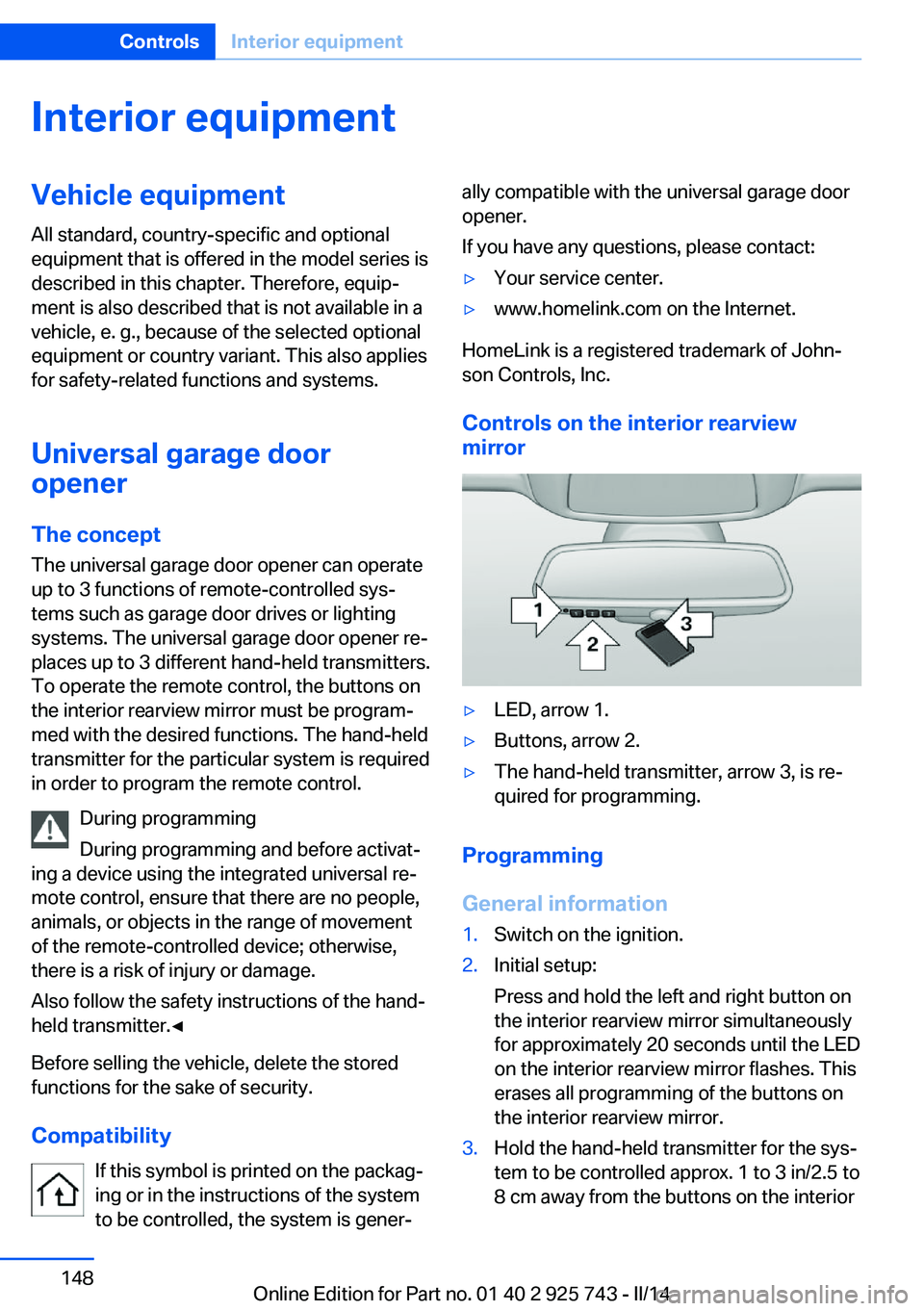
Controls on the interior rearview
mirror
▷LED, arrow 1.▷Buttons, arrow 2.▷The hand-held transmitter, arrow 3, is re‐
quired for programming.
Programming
General information
1.Switch on the ignition.2.Initial setup:
Press and hold the left and right button on
the interior rearview mirror simultaneously
for approximately 20 seconds until the LED
on the interior rearview mirror flashes. This
erases all programming of the buttons on
the interior rearview mirror.3.Hold the hand-held transmitter for the sys‐
tem to be controlled approx. 1 to 3 in/2.5 to
8 cm away from the buttons on the interiorSeite 148ControlsInterior equipment148
Online Edition for Part no. 01 40 2 925 743 - II/14