2014 BMW 328I XDRIVE GRAN TURISMO remote control
[x] Cancel search: remote controlPage 112 of 240
NotesPersonal responsibility
The system cannot serve as a substitute
for the driver's personal judgment of the
course of the road and the traffic situation.
In the event of a warning, do not jerk the steer‐
ing wheel, as you may lose control of the vehi‐
cle.◀
At a glance
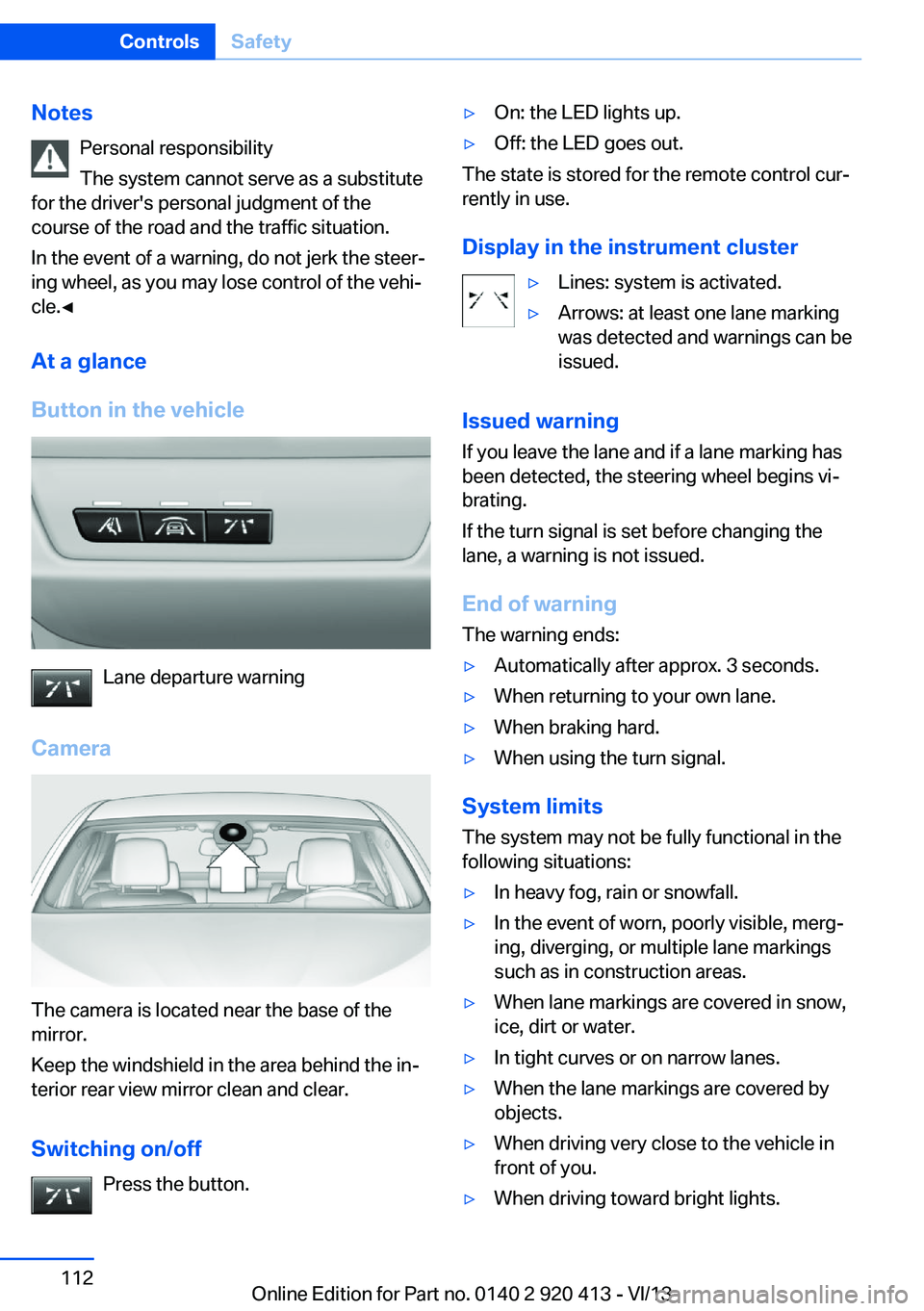
Button in the vehicle
Lane departure warning
Camera
The camera is located near the base of the
mirror.
Keep the windshield in the area behind the in‐
terior rear view mirror clean and clear.
Switching on/off Press the button.
▷On: the LED lights up.▷Off: the LED goes out.
The state is stored for the remote control cur‐
rently in use.
Display in the instrument cluster
▷Lines: system is activated.▷Arrows: at least one lane marking
was detected and warnings can be
issued.
Issued warning
If you leave the lane and if a lane marking has
been detected, the steering wheel begins vi‐
brating.
If the turn signal is set before changing the
lane, a warning is not issued.
End of warning
The warning ends:
▷Automatically after approx. 3 seconds.▷When returning to your own lane.▷When braking hard.▷When using the turn signal.
System limits
The system may not be fully functional in the
following situations:
▷In heavy fog, rain or snowfall.▷In the event of worn, poorly visible, merg‐
ing, diverging, or multiple lane markings
such as in construction areas.▷When lane markings are covered in snow,
ice, dirt or water.▷In tight curves or on narrow lanes.▷When the lane markings are covered by
objects.▷When driving very close to the vehicle in
front of you.▷When driving toward bright lights.Seite 112ControlsSafety112
Online Edition for Part no. 0140 2 920 413 - VI/13
Page 113 of 240
▷When the windshield in front of the interior
rearview mirror is fogged over, dirty or cov‐
ered with stickers, etc.▷During calibration of the camera immedi‐
ately after vehicle shipment.
Active Blind Spot Detection
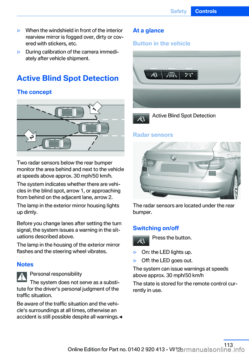
The concept
Two radar sensors below the rear bumper
monitor the area behind and next to the vehicle
at speeds above approx. 30 mph/50 km/h.
The system indicates whether there are vehi‐
cles in the blind spot, arrow 1, or approaching
from behind on the adjacent lane, arrow 2.
The lamp in the exterior mirror housing lights
up dimly.
Before you change lanes after setting the turn
signal, the system issues a warning in the sit‐
uations described above.
The lamp in the housing of the exterior mirror
flashes and the steering wheel vibrates.
Notes Personal responsibility
The system does not serve as a substi‐
tute for the driver's personal judgment of the
traffic situation.
Be aware of the traffic situation and the vehi‐
cle's surroundings at all times, otherwise an
accident is still possible despite all warnings.◀
At a glance
Button in the vehicle
Active Blind Spot Detection
Radar sensors
The radar sensors are located under the rear
bumper.
Switching on/off Press the button.
▷On: the LED lights up.▷Off: the LED goes out.
The system can issue warnings at speeds
above approx. 30 mph/50 km/h
The state is stored for the remote control cur‐
rently in use.
Seite 113SafetyControls113
Online Edition for Part no. 0140 2 920 413 - VI/13
Page 121 of 240
SPORT+Sporty driving with optimized chassis and
adapted engine control with limited driving sta‐
bilization.
Dynamic Traction Control is switched on.
The driver handles several of the stabilization
tasks.
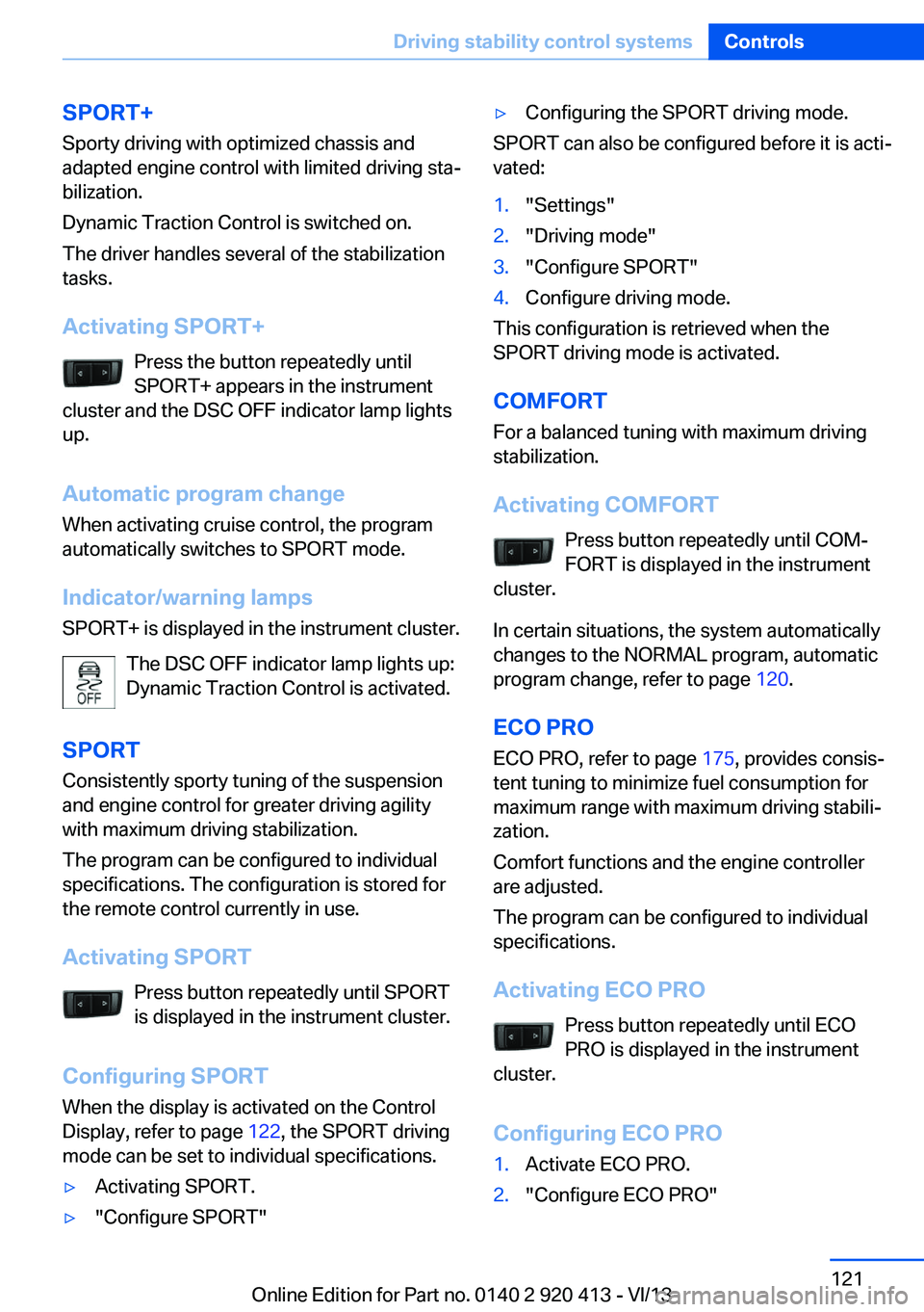
Activating SPORT+ Press the button repeatedly until
SPORT+ appears in the instrument
cluster and the DSC OFF indicator lamp lights
up.
Automatic program change
When activating cruise control, the program
automatically switches to SPORT mode.
Indicator/warning lamps
SPORT+ is displayed in the instrument cluster.
The DSC OFF indicator lamp lights up:
Dynamic Traction Control is activated.
SPORT Consistently sporty tuning of the suspension
and engine control for greater driving agility
with maximum driving stabilization.
The program can be configured to individual
specifications. The configuration is stored for
the remote control currently in use.
Activating SPORT Press button repeatedly until SPORT
is displayed in the instrument cluster.
Configuring SPORT
When the display is activated on the Control
Display, refer to page 122, the SPORT driving
mode can be set to individual specifications.▷Activating SPORT.▷"Configure SPORT"▷Configuring the SPORT driving mode.
SPORT can also be configured before it is acti‐
vated:
1."Settings"2."Driving mode"3."Configure SPORT"4.Configure driving mode.
This configuration is retrieved when the
SPORT driving mode is activated.
COMFORT For a balanced tuning with maximum driving
stabilization.
Activating COMFORT Press button repeatedly until COM‐
FORT is displayed in the instrument
cluster.
In certain situations, the system automatically
changes to the NORMAL program, automatic
program change, refer to page 120.
ECO PRO ECO PRO, refer to page 175, provides consis‐
tent tuning to minimize fuel consumption for
maximum range with maximum driving stabili‐
zation.
Comfort functions and the engine controller
are adjusted.
The program can be configured to individual
specifications.
Activating ECO PRO Press button repeatedly until ECO
PRO is displayed in the instrument
cluster.
Configuring ECO PRO
1.Activate ECO PRO.2."Configure ECO PRO"Seite 121Driving stability control systemsControls121
Online Edition for Part no. 0140 2 920 413 - VI/13
Page 132 of 240
▷By the front middle sensors and the two
corner sensors at approx. 24 in/60 cm.▷By the rear middle sensors at approx.
5 ft/1.50 m.
Notes
Check the traffic situation as well
PDC cannot serve as a substitute for the
driver's personal judgment of the traffic situa‐
tion. Check the traffic situation around the ve‐
hicle with your own eyes. Otherwise, an acci‐
dent could result from road users or objects
located outside of the PDC detection range.
Loud noises from outside and inside the vehi‐ cle may prevent you from hearing the PDC's
signal tone.◀
Avoid driving quickly with PDC
Avoid approaching an object quickly.
Avoid driving away quickly while PDC is not yet
active.
For technical reasons, the system may other‐
wise be too late in issuing a warning.◀
At a glance
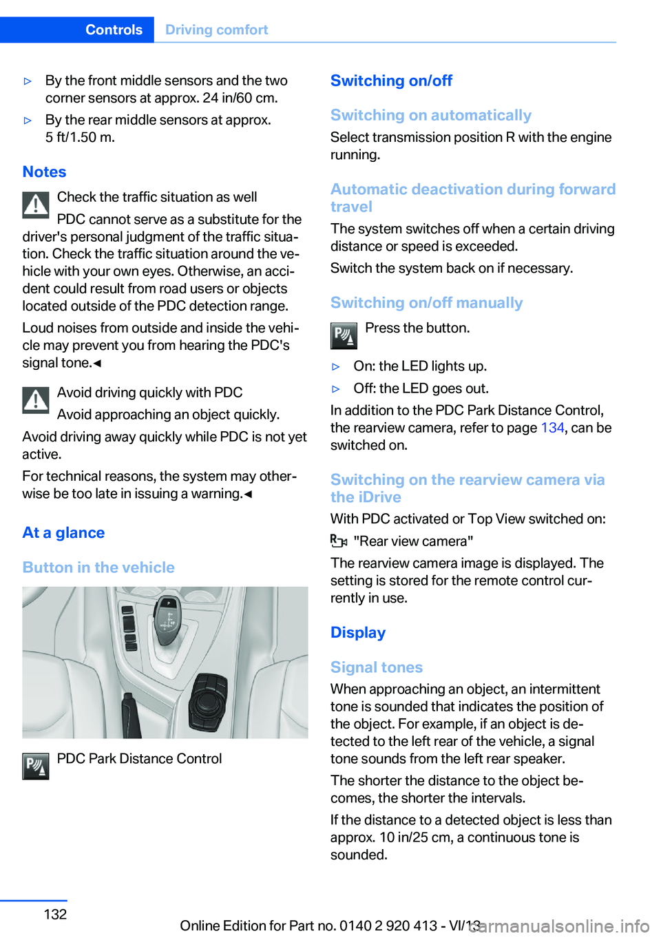
Button in the vehicle
PDC Park Distance Control
Switching on/off
Switching on automatically Select transmission position R with the engine
running.
Automatic deactivation during forward travel
The system switches off when a certain driving
distance or speed is exceeded.
Switch the system back on if necessary.
Switching on/off manually Press the button.▷On: the LED lights up.▷Off: the LED goes out.
In addition to the PDC Park Distance Control,
the rearview camera, refer to page 134, can be
switched on.
Switching on the rearview camera viathe iDrive
With PDC activated or Top View switched on:
"Rear view camera"
The rearview camera image is displayed. The
setting is stored for the remote control cur‐
rently in use.
Display
Signal tones When approaching an object, an intermittent
tone is sounded that indicates the position of
the object. For example, if an object is de‐
tected to the left rear of the vehicle, a signal
tone sounds from the left rear speaker.
The shorter the distance to the object be‐
comes, the shorter the intervals.
If the distance to a detected object is less than
approx. 10 in/25 cm, a continuous tone is
sounded.
Seite 132ControlsDriving comfort132
Online Edition for Part no. 0140 2 920 413 - VI/13
Page 133 of 240
If objects are located both in front of and be‐
hind the vehicle, an alternating continuous sig‐
nal is sounded.
The intermittent tone is interrupted after ap‐
prox. 3 seconds:▷If the vehicle stops in front of an object that
is detected by only one of the corner sen‐
sors.▷If moving parallel to a wall.
The signal tone is switched off:
▷When the vehicle moves away from an ob‐
ject by more than approx. 4 in/10 cm.▷When transmission position P is engaged.
Volume
The volume of the PDC signal can be adjusted,
refer to user's manual for Navigation, Enter‐
tainment, Communication.
The setting is stored for the remote control
currently in use.
Visual warning
The approach of the vehicle to an object can
be shown on the Control Display. Objects that
are farther away are displayed on the Control
Display before a signal tone sounds.
A display appears as soon as Park Distance
Control (PDC) is activated.
The range of the sensors is represented in the
colors red, green and yellow.
If the rearview camera image was selected last,
it again appears on the display. To switch to
PDC:
1. "Rear view camera" Select the symbol
on the Control Display.2.Press the controller.
The setting is stored for the remote control
currently in use.
System limits
Limits of ultrasonic measurement
The detection of objects can reach the physi‐
cal limits of ultrasonic measurement, e.g.:▷With tow bars and trailer hitches.▷With thin or wedge-shaped objects.▷With low objects.▷With objects with corners and sharp edges.
Low objects already displayed, e.g., curbs, can
move into the blind area of the sensors before
or after a continuous tone sounds.
High, protruding objects such as ledges may
not be detected.
False warnings
PDC may issue a warning under the following
conditions even though there is no obstacle
within the detection range:
▷In heavy rain.▷When sensors are very dirty or covered in
ice.▷When sensors are covered in snow.▷On rough road surfaces.▷In large buildings with right angles and
smooth walls, e.g., in underground ga‐
rages.▷In heavy exhaust.▷Due to other ultrasound sources, e.g.,
sweeping machines, high pressure steam
cleaners or neon lights.
The malfunction is signaled by a continu‐
ous tone alternating between the front and
rear speakers. As soon as the malfunction
due to other ultrasound sources is no lon‐
ger present, the system is again fully func‐
tional.
Malfunction
A Check Control message is displayed.
Seite 133Driving comfortControls133
Online Edition for Part no. 0140 2 920 413 - VI/13
Page 135 of 240
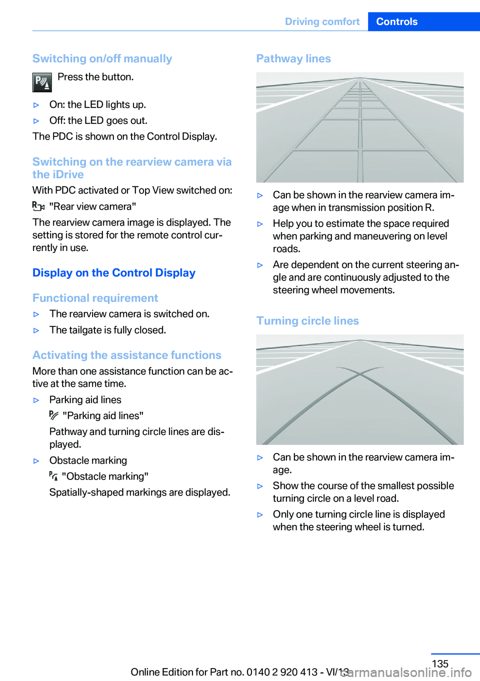
Switching on/off manuallyPress the button.▷On: the LED lights up.▷Off: the LED goes out.
The PDC is shown on the Control Display.
Switching on the rearview camera via
the iDrive
With PDC activated or Top View switched on:
"Rear view camera"
The rearview camera image is displayed. The
setting is stored for the remote control cur‐
rently in use.
Display on the Control Display
Functional requirement
▷The rearview camera is switched on.▷The tailgate is fully closed.
Activating the assistance functions
More than one assistance function can be ac‐
tive at the same time.
▷Parking aid lines
"Parking aid lines"
Pathway and turning circle lines are dis‐
played.
▷Obstacle marking
"Obstacle marking"
Spatially-shaped markings are displayed.
Pathway lines▷Can be shown in the rearview camera im‐
age when in transmission position R.▷Help you to estimate the space required
when parking and maneuvering on level
roads.▷Are dependent on the current steering an‐
gle and are continuously adjusted to the
steering wheel movements.
Turning circle lines
▷Can be shown in the rearview camera im‐
age.▷Show the course of the smallest possible
turning circle on a level road.▷Only one turning circle line is displayed
when the steering wheel is turned.Seite 135Driving comfortControls135
Online Edition for Part no. 0140 2 920 413 - VI/13
Page 139 of 240
Switching on the backup camera via
the iDrive
With Top View switched on:
"Rear view camera"
The backup camera image is displayed. The
setting is stored for the remote control cur‐
rently in use.
Display
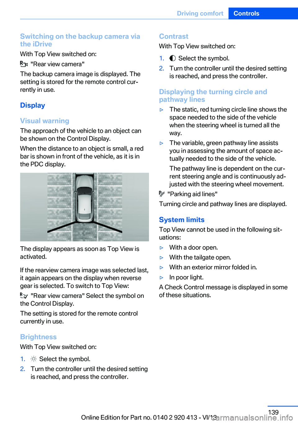
Visual warning The approach of the vehicle to an object can
be shown on the Control Display.
When the distance to an object is small, a red
bar is shown in front of the vehicle, as it is in
the PDC display.
The display appears as soon as Top View is
activated.
If the rearview camera image was selected last,
it again appears on the display when reverse
gear is selected. To switch to Top View:
"Rear view camera" Select the symbol on
the Control Display.
The setting is stored for the remote control
currently in use.
Brightness
With Top View switched on:
1. Select the symbol.2.Turn the controller until the desired setting
is reached, and press the controller.Contrast
With Top View switched on:1. Select the symbol.2.Turn the controller until the desired setting
is reached, and press the controller.
Displaying the turning circle and
pathway lines
▷The static, red turning circle line shows the
space needed to the side of the vehicle
when the steering wheel is turned all the
way.▷The variable, green pathway line assists
you in assessing the amount of space ac‐
tually needed to the side of the vehicle.
The pathway line is dependent on the cur‐
rent steering angle and is continuously ad‐
justed with the steering wheel movement.
"Parking aid lines"
Turning circle and pathway lines are displayed.
System limits
Top View cannot be used in the following sit‐
uations:
▷With a door open.▷With the tailgate open.▷With an exterior mirror folded in.▷In poor light.
A Check Control message is displayed in some
of these situations.
Seite 139Driving comfortControls139
Online Edition for Part no. 0140 2 920 413 - VI/13
Page 144 of 240
Head-up Display
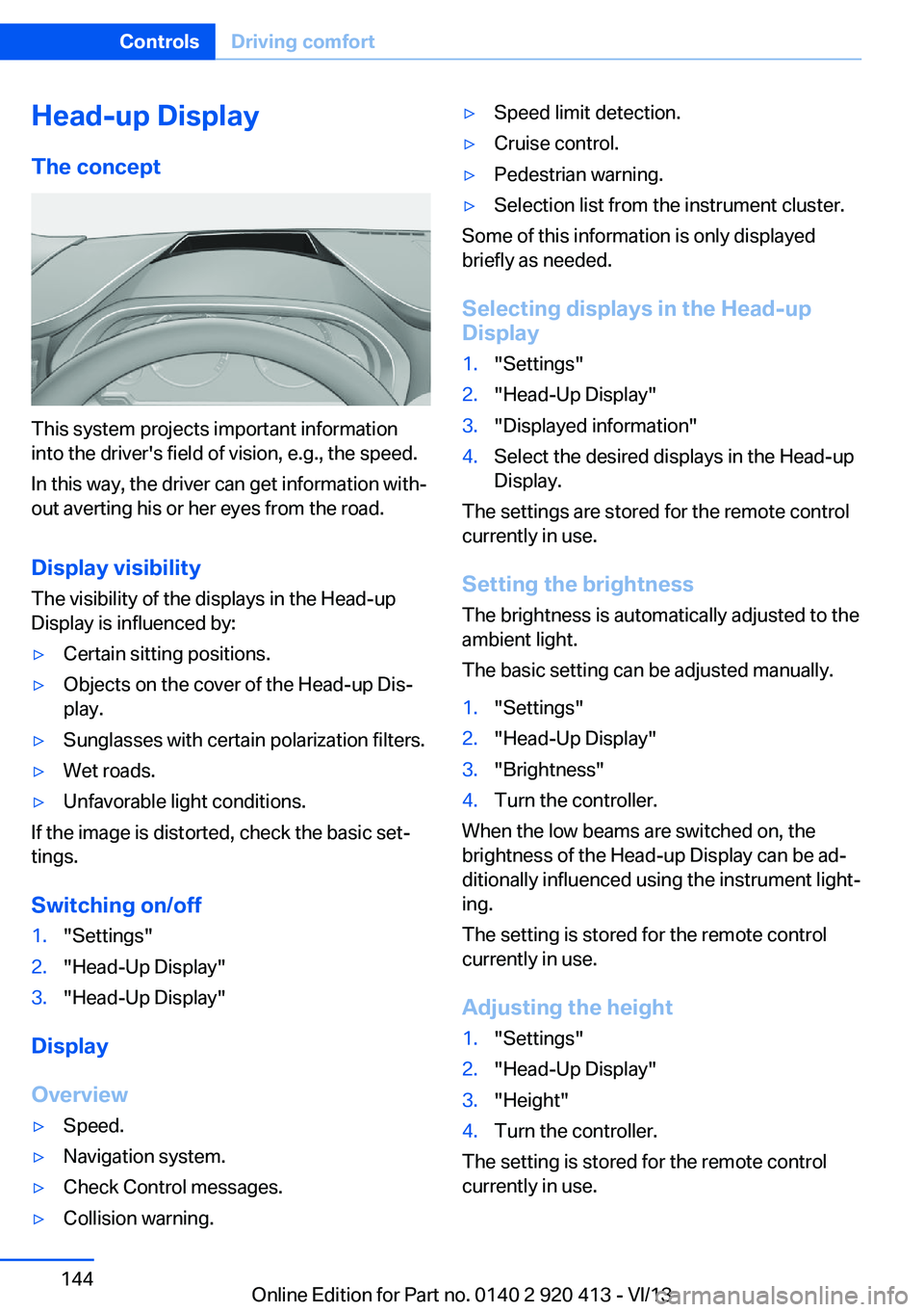
The concept
This system projects important information
into the driver's field of vision, e.g., the speed.
In this way, the driver can get information with‐
out averting his or her eyes from the road.
Display visibility The visibility of the displays in the Head-up
Display is influenced by:
▷Certain sitting positions.▷Objects on the cover of the Head-up Dis‐
play.▷Sunglasses with certain polarization filters.▷Wet roads.▷Unfavorable light conditions.
If the image is distorted, check the basic set‐
tings.
Switching on/off
1."Settings"2."Head-Up Display"3."Head-Up Display"
Display
Overview
▷Speed.▷Navigation system.▷Check Control messages.▷Collision warning.▷Speed limit detection.▷Cruise control.▷Pedestrian warning.▷Selection list from the instrument cluster.
Some of this information is only displayed
briefly as needed.
Selecting displays in the Head-up
Display
1."Settings"2."Head-Up Display"3."Displayed information"4.Select the desired displays in the Head-up
Display.
The settings are stored for the remote control
currently in use.
Setting the brightness
The brightness is automatically adjusted to the
ambient light.
The basic setting can be adjusted manually.
1."Settings"2."Head-Up Display"3."Brightness"4.Turn the controller.
When the low beams are switched on, the
brightness of the Head-up Display can be ad‐
ditionally influenced using the instrument light‐
ing.
The setting is stored for the remote control
currently in use.
Adjusting the height
1."Settings"2."Head-Up Display"3."Height"4.Turn the controller.
The setting is stored for the remote control
currently in use.
Seite 144ControlsDriving comfort144
Online Edition for Part no. 0140 2 920 413 - VI/13