2014 BMW 328D XDRIVE height
[x] Cancel search: heightPage 58 of 242
On the front passenger seat
Deactivating airbags
After installing a child restraint fixing system in
the front passenger seat, make sure that the
front, knee and side airbags on the front pas‐
senger side are deactivated.
Deactivate the front passenger airbags auto‐
matically, refer to page 96.
Deactivating the front passenger airbags
If a child restraint fixing system is used in
the front passenger seat, the front passenger
airbags must be deactivated; otherwise, there
is an increased risk of injury to the child when
the airbags are triggered, even with a child re‐
straint fixing system.◀
Seat position and height
Before installing a child restraint fixing system,
move the front passenger seat as far back as
possible and adjust its height to the highest
position to obtain the best possible position for
the belt and to offer optimal protection in the
event of an accident.
If the upper fixing point of the safety belt is lo‐
cated before the belt guide of the child seat,
move the passenger seat carefully forward un‐
til the best possible belt guide position is
reached.
Backrest width Adjustable backrest width: before installing a
child restraint fixing system in the front pas‐
senger seat, open the backrest width com‐
pletely. Do not change the backrest width
again and do not call up a memory position.Backrest width for the child seat
Before installing a child restraint fixing
system in the front passenger seat, the back‐
rest width must be opened completely. Do not
change the adjustment after this; otherwise,
the stability of the child seat will be reduced.◀
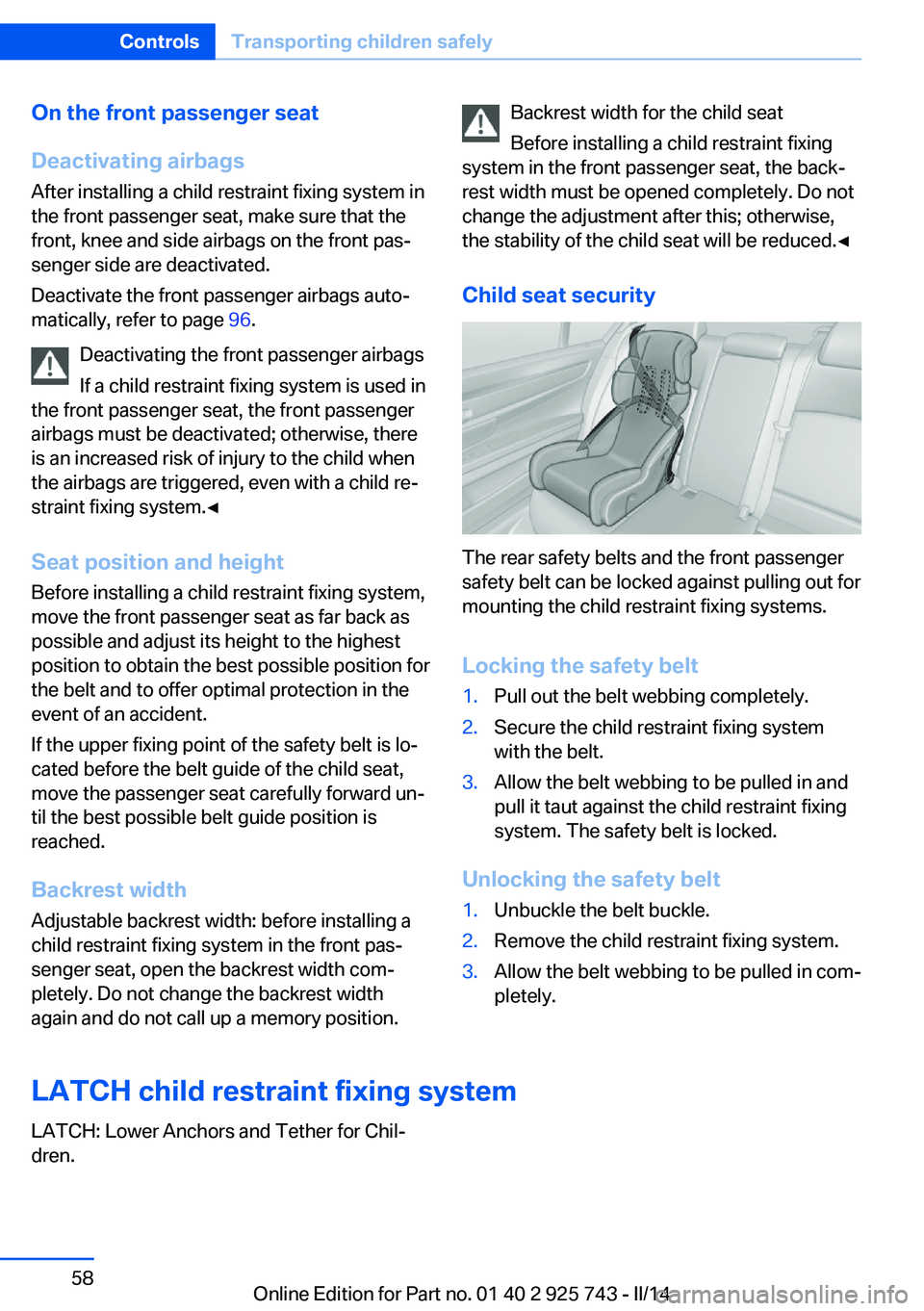
Child seat security
The rear safety belts and the front passenger
safety belt can be locked against pulling out for
mounting the child restraint fixing systems.
Locking the safety belt
1.Pull out the belt webbing completely.2.Secure the child restraint fixing system
with the belt.3.Allow the belt webbing to be pulled in and
pull it taut against the child restraint fixing
system. The safety belt is locked.
Unlocking the safety belt
1.Unbuckle the belt buckle.2.Remove the child restraint fixing system.3.Allow the belt webbing to be pulled in com‐
pletely.
LATCH child restraint fixing system
LATCH: Lower Anchors and Tether for Chil‐
dren.Seite 58ControlsTransporting children safely58
Online Edition for Part no. 01 40 2 925 743 - II/14
Page 88 of 242
▷Driver assistance systems.
Some of this information is only displayed
briefly as needed.
Selecting displays in the Head-up
Display
1."Settings"2."Head-Up Display"3."Displayed information"4.Select the desired displays in the Head-up
Display.
The settings are stored for the remote control
currently in use.
Setting the brightness
The brightness is automatically adjusted to the
ambient light.
The basic setting can be adjusted manually.
1."Settings"2."Head-Up Display"3."Brightness"4.Turn the controller.
When the low beams are switched on, the
brightness of the Head-up Display can be ad‐
ditionally influenced using the instrument light‐
ing.
The setting is stored for the remote control
currently in use.
Adjusting the height
1."Settings"2."Head-Up Display"3."Height"4.Turn the controller.
The setting is stored for the remote control
currently in use.
Setting the rotation
1."Settings"2."Head-Up Display"3."Rotation"4.Turn the controller.
The setting is stored for the remote control
currently in use.
Special windshield
The windshield is part of the system.
The shape of the windshield makes it possible
to display a precise image.
A film in the windshield prevents double im‐
ages from being displayed.
Therefore, have the special windshield re‐
placed by a service center only.
Seite 88ControlsDisplays88
Online Edition for Part no. 01 40 2 925 743 - II/14
Page 134 of 242
Switch the system back on if necessary.
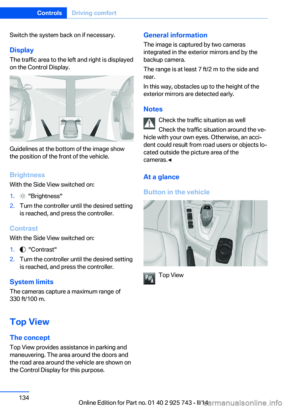
Display The traffic area to the left and right is displayed
on the Control Display.
Guidelines at the bottom of the image show
the position of the front of the vehicle.
Brightness With the Side View switched on:
1. "Brightness"2.Turn the controller until the desired setting
is reached, and press the controller.
Contrast
With the Side View switched on:
1. "Contrast"2.Turn the controller until the desired setting
is reached, and press the controller.
System limits
The cameras capture a maximum range of
330 ft/100 m.
Top View
The concept Top View provides assistance in parking and
maneuvering. The area around the doors and
the road area around the vehicle are shown on
the Control Display for this purpose.
General information
The image is captured by two cameras
integrated in the exterior mirrors and by the
backup camera.
The range is at least 7 ft/2 m to the side and
rear.
In this way, obstacles up to the height of the
exterior mirrors are detected early.
Notes Check the traffic situation as well
Check the traffic situation around the ve‐
hicle with your own eyes. Otherwise, an acci‐
dent could result from road users or objects lo‐
cated outside the picture area of the
cameras.◀
At a glance
Button in the vehicle
Top View
Seite 134ControlsDriving comfort134
Online Edition for Part no. 01 40 2 925 743 - II/14
Page 154 of 242
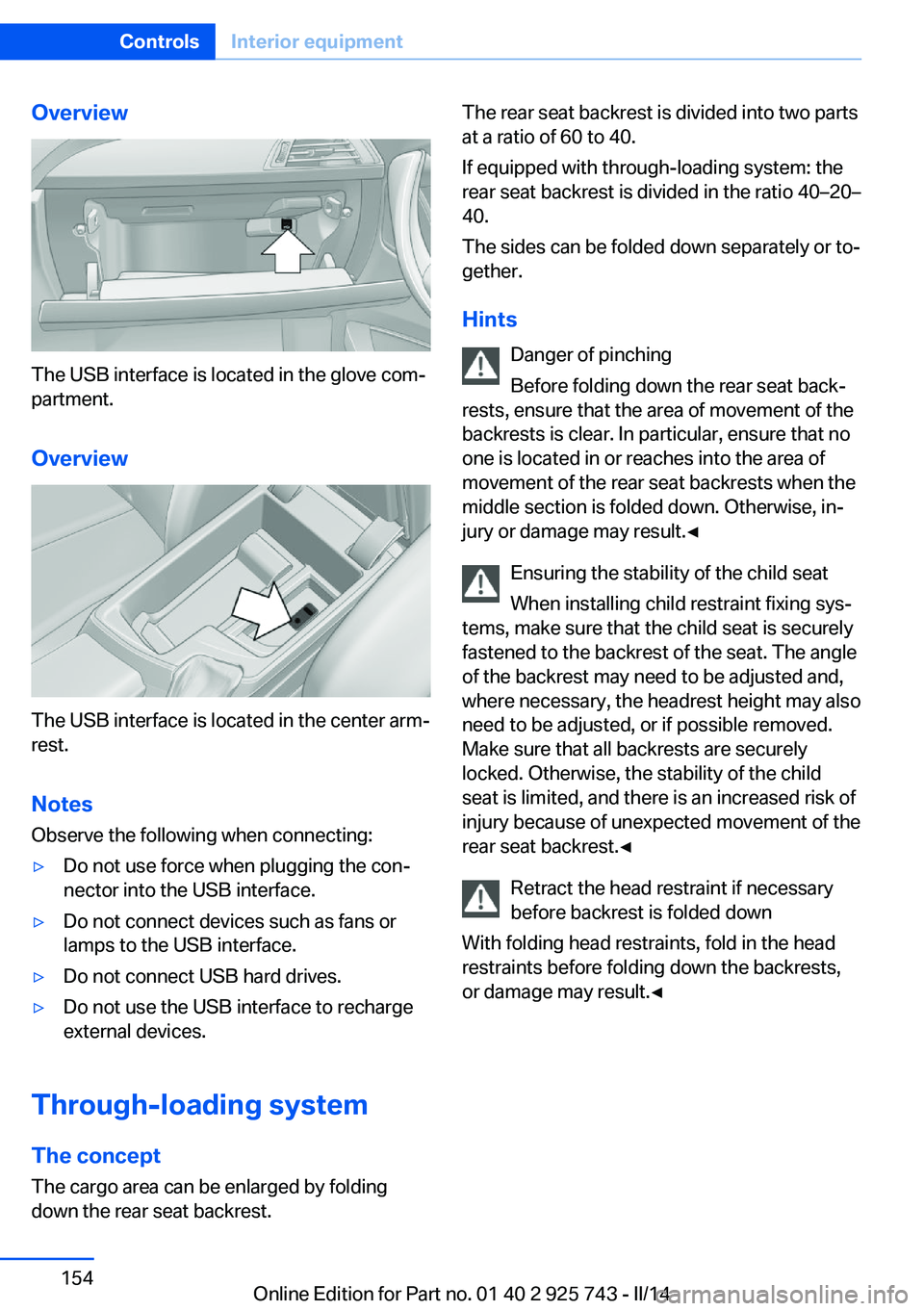
Overview
The USB interface is located in the glove com‐
partment.
Overview
The USB interface is located in the center arm‐
rest.
Notes Observe the following when connecting:
▷Do not use force when plugging the con‐
nector into the USB interface.▷Do not connect devices such as fans or
lamps to the USB interface.▷Do not connect USB hard drives.▷Do not use the USB interface to recharge
external devices.
Through-loading system
The concept The cargo area can be enlarged by folding
down the rear seat backrest.
The rear seat backrest is divided into two parts at a ratio of 60 to 40.
If equipped with through-loading system: the
rear seat backrest is divided in the ratio 40–20– 40.
The sides can be folded down separately or to‐
gether.
Hints Danger of pinching
Before folding down the rear seat back‐
rests, ensure that the area of movement of the
backrests is clear. In particular, ensure that no
one is located in or reaches into the area of
movement of the rear seat backrests when the
middle section is folded down. Otherwise, in‐
jury or damage may result.◀
Ensuring the stability of the child seat
When installing child restraint fixing sys‐
tems, make sure that the child seat is securely
fastened to the backrest of the seat. The angle
of the backrest may need to be adjusted and,
where necessary, the headrest height may also
need to be adjusted, or if possible removed.
Make sure that all backrests are securely
locked. Otherwise, the stability of the child
seat is limited, and there is an increased risk of
injury because of unexpected movement of the
rear seat backrest.◀
Retract the head restraint if necessary
before backrest is folded down
With folding head restraints, fold in the head
restraints before folding down the backrests,
or damage may result.◀Seite 154ControlsInterior equipment154
Online Edition for Part no. 01 40 2 925 743 - II/14
Page 163 of 242
Hot exhaust systemHot exhaust system
High temperatures are generated in the
exhaust system.
Do not remove the heat shields installed and
never apply undercoating to them. Make sure
that flammable materials, e. g. hay, leaves,
grass, etc. do not come in contact with the hot
exhaust system during driving, while in idle po‐
sition mode, or when parked. Such contact
could lead to a fire, and with it the risk of seri‐
ous personal injury as well as property dam‐
age.
Do not touch hot exhaust pipes; otherwise,
there is the danger of getting burned.◀
Diesel particulate filter The diesel particulate filter collects soot parti‐
cles and burns them periodically at high tem‐
peratures.
During the cleaning time of several minutes,
the following may occur:▷Temporarily, the engine may run less
smoothly.▷Noises and a slight amount of smoke com‐
ing from the exhaust until shortly after the
engine is shut down.▷A somewhat higher engine speed is neces‐
sary to achieve the accustomed perform‐
ance.
Mobile communication devices in the
vehicle
Mobile communication devices in the ve‐
hicle
It is advised that you do not use mobile com‐
munication devices, e.g., mobile phones, in‐
side the vehicle without connecting them di‐
rectly to the external antenna. Otherwise, the
vehicle electronics and mobile communication
devices can interfere with each other. In addi‐
tion, there is no assurance that the radiation
generated during transmission will be dis‐
charged from the vehicle interior.◀
Hydroplaning
On wet or slushy roads, a wedge of water can
form between the tires and road surface.
This phenomenon is referred to as hydroplan‐
ing. It is characterized by a partial or complete
loss of contact between the tires and the road
surface, ultimately undermining your ability to
steer and brake the vehicle.
Hydroplaning
When driving on wet or slushy roads, re‐
duce your speed to prevent hydroplaning.◀
Driving through water Adhere to water depth and speed limita‐
tions
Do not exceed this water depth and walking
speed; otherwise, the vehicle's engine, the
electrical systems and the transmission may
be damaged.◀
Drive through calm water only and only if it is
not deeper than. 9.8 inches/25 cm and at this
height, no faster than walking speed, up to
6 mph/10 km/h.
Braking safely Your vehicle is equipped with ABS as a stand‐
ard feature.
Applying the brakes fully is the most effective
way of braking in situations when this is neces‐
sary.
The vehicle maintains steering responsive‐
ness. You can still avoid any obstacles with a
minimum of steering effort.
Pulsation of the brake pedal and sounds from
the hydraulic circuits indicate that ABS is in its
active mode.Seite 163Things to remember when drivingDriving tips163
Online Edition for Part no. 01 40 2 925 743 - II/14
Page 193 of 242

Tire treadSummer tires
Do not drive with a tire tread depth of less than
0.12 in/3 mm.
There is an increased danger of hydroplaning if
the tread depth is less than 0.12 in/3 mm.
Winter tires Do not drive with a tire tread depth of less than
0.16 in/4 mm.
Below a tread depth of 0.16 in/4 mm, tires are
less suitable for winter operation.
Minimum tread depth
Wear indicators are distributed around the
tire's circumference and have the legally re‐
quired minimum height of 0.063 in/1.6 mm.
They are marked on the side of the tire with
TWI, Tread Wear Indicator.
Tire damage
General information
Inspect your tires often for damage, foreign
objects lodged in the tread, and tread wear.
Notes
Driving over rough or damaged road surfaces,
as well as debris, curbs and other obstacles can cause serious damage to wheels, tires and
suspension parts. This is more likely to occur
with low-profile tires, which provide less cush‐
ioning between the wheel and the road. Be
careful to avoid road hazards and reduce your
speed, especially if your vehicle is equipped
with low-profile tires.
Indications of tire damage or other vehicle de‐
fects:▷Unusual vibrations during driving.▷Unusual handling such as a strong ten‐
dency to pull to the left or right.
Damage can, e. g., be caused by driving over
curbs, road damage, or similar things.
In case of tire damage
If there are indications of tire damage, re‐
duce your speed immediately and have the
wheels and tires checked right away; other‐
wise, there is the increased risk of an accident.
Drive carefully to the nearest service center.
Have the vehicle towed or transported there.
Otherwise, tire damage can become life threat‐
ening for vehicle occupants and also other
road users.◀
Repair of tire damage
For safety reasons, the manufacturer of
your vehicle recommends that you do not have
damaged tires repaired; they should be re‐
placed. Otherwise, damage can occur as a re‐
sult.◀
Changing wheels and tires
Mounting Information on mounting tires
Have mounting and balancing performed
only by a service center.
If this work is not carried out properly, there is
the danger of subsequent damage and related
safety hazards.◀
Seite 193Wheels and tiresMobility193
Online Edition for Part no. 01 40 2 925 743 - II/14
Page 197 of 242
Hood
Hints Working in the engine compartment
Never attempt to perform any service or
repair operations on your vehicle without the
necessary professional technical training.
If you are unfamiliar with the statutory guide‐
lines, have any work on the vehicle performed
only by a service center.
If this work is not carried out properly, there is
the danger of subsequent damage and related
safety hazards.◀
Never reach into the engine compart‐
ment
Never reach into the intermediate spaces or
gaps in the engine compartment. Otherwise,
there is risk of injury, e.g., from rotating or hot
parts.◀
Fold down wiper arm
Before opening the hood, ensure that the
wiper arms are against the windshield, or this
may result in damage.◀
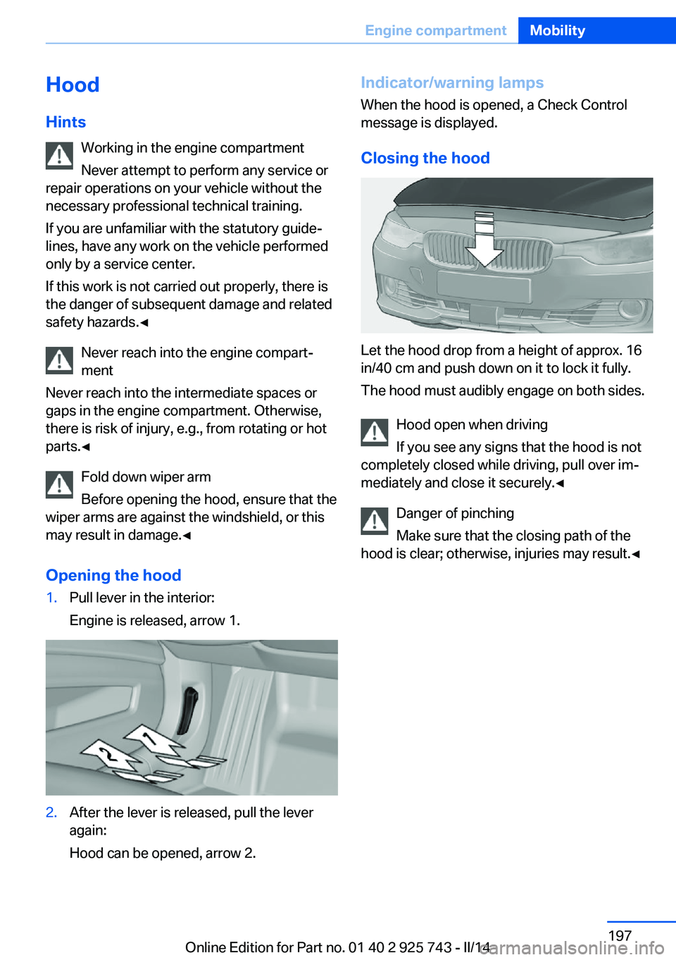
Opening the hood1.Pull lever in the interior:
Engine is released, arrow 1.2.After the lever is released, pull the lever
again:
Hood can be opened, arrow 2.Indicator/warning lamps
When the hood is opened, a Check Control
message is displayed.
Closing the hood
Let the hood drop from a height of approx. 16
in/40 cm and push down on it to lock it fully.
The hood must audibly engage on both sides.
Hood open when driving
If you see any signs that the hood is not
completely closed while driving, pull over im‐
mediately and close it securely.◀
Danger of pinching
Make sure that the closing path of the
hood is clear; otherwise, injuries may result.◀
Seite 197Engine compartmentMobility197
Online Edition for Part no. 01 40 2 925 743 - II/14
Page 228 of 242

Technical dataVehicle equipment
All standard, country-specific and optional
equipment that is offered in the model series is
described in this chapter. Therefore, equip‐
ment is also described that is not available in a
vehicle, e. g., because of the selected optional
equipment or country variant. This also applies
for safety-related functions and systems.
Seite 228ReferenceTechnical data228
Online Edition for Part no. 01 40 2 925 743 - II/14Dimensions
BMW 3 Series LimousineWidth with mirrorsinches/mm79.9/2,031Width without mirrorsinches/mm71.3/1,811Heightinches/mm56.4/1,434Lengthinches/mm182.2/4,627Wheel baseinches/mm110.6/2,810Smallest turning circle diam.ft/m37.1/11.3Smallest turning circle diameter with xDriveft/m38.4/11.7
Weights
The values preceding the slash apply to vehi‐
cles with manual transmission; the values fol‐
lowing the slash apply to vehicles with auto‐
matic transmission.
320iApproved gross vehicle weightlbs
kg
4,300/4,340
1,950/1,969
Loadlbs/kg900/408Approved front axle loadlbs/kg1,985/900Approved rear axle loadlbs/kg2,480/1,125Approved roof load capacitylbs/kg165/75Cargo area capacitycu ft/l16.9/480