Page 113 of 242

and the lamp in the mirror housing flashes
brightly.
The warning stops when the turn signal is
switched off, or the other vehicle leaves the
critical zone.
System limits
The system may not be fully functional in the
following situations:▷When a vehicle is approaching at a speed
much faster than your own.▷In heavy fog, rain or snowfall.▷In tight curves or on narrow lanes.▷If the bumper is dirty or iced up, or covered
with stickers.
A Check Control message is displayed when
the system is not fully functional.
For US owners only The transmitter and receiver units comply with
part 15 of the FCC/Federal Communication
Commission regulations. Operation is gov‐
erned by the following:
FCC ID:
▷NBG009014A.
Compliance statement:
This device complies with part 15 of the FCC
Rules. Operation is subject to the following
two conditions:
▷This device may not cause harmful inter‐
ference, and▷this device must accept any interference
received, including interference that may
cause undesired operation.
Any unauthorized modifications or changes to
these devices could void the user's authority to
operate this equipment.
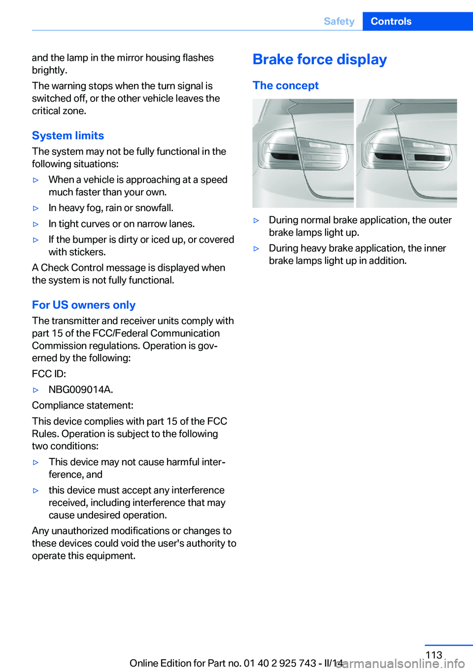
Brake force display
The concept▷During normal brake application, the outer
brake lamps light up.▷During heavy brake application, the inner
brake lamps light up in addition.Seite 113SafetyControls113
Online Edition for Part no. 01 40 2 925 743 - II/14
Page 119 of 242

Driving comfortVehicle equipment
All standard, country-specific and optional
equipment that is offered in the model series is
described in this chapter. Therefore, equip‐
ment is also described that is not available in a
vehicle, e. g., because of the selected optional
equipment or country variant. This also applies
for safety-related functions and systems.
Active Cruise Control with Stop & Go function, ACC
The conceptThis system can be used to select a desired
speed that the vehicle will maintain automati‐
cally on clear roads.
To the extent possible, the system automati‐
cally adjusts the speed to a slower vehicle
ahead of you.
The distance that the vehicle maintains to the
vehicle ahead of you can be varied.
For safety reasons, it depends on the speed.
To maintain a certain distance, the system au‐
tomatically reduces the speed, applies the
brakes lightly, or accelerates again if the vehi‐
cle ahead begins moving faster.
If the vehicle ahead of you brakes to a halt, the
system is able to detect this within the given
system limits. If the vehicle ahead of your
drives away again from a halt, your vehicle is
able to accelerate if operated accordingly.
Even if some time passes before the vehicle
ahead of you drives away again, your own vehi‐
cle can still be accelerated automatically and
simply.
As soon as the road is clear, it accelerates to
the desired speed.The speed is also maintained on downhill gra‐
dients, but may not be maintained on uphill
slopes if engine power is insufficient.
General information
Depending on the set driving program, the
characteristics of the cruise control can
change in certain areas.
Hints Personal responsibility
Even an active system does not release
the driver from personal responsibility for the
driving process, especially for lane tracking,
adaptation of speed, distance and driving style
to the traffic conditions.
Because of technical system limits, the system
cannot independently react appropriately in all
traffic situations.
Monitor the driving process, the surrounding
area and what is occurring in traffic continu‐
ously and attentively and actively intervene as
required, e.g., by braking, steering or making an evasive maneuver.◀
Unfavorable weather conditions
In the event of unfavorable weather and
light conditions, e. g. if there is rain, snowfall,
slush, fog or glare, this may result in poorer
recognition of vehicles as well as short-term
interruptions for vehicles that are already de‐
tected. Drive attentively, and react to the cur‐
rent traffic events. Intervene actively when
necessary, e.g., by braking, steering or making
an evasive maneuver, otherwise, there is dan‐
ger of an accident.◀Seite 119Driving comfortControls119
Online Edition for Part no. 01 40 2 925 743 - II/14
Page 208 of 242

Daytime running lights
24-watt bulb, PW24W.1.If necessary, remove the high beam bulb
connector.2.Remove the bulb holder.3.Remove the bulb from the bulb holder.4.To insert the new bulb, proceed in reverse
order of removal. During insertion, the bot‐
tom of the bulb holder must be facing
downward. Make sure that the bulb holder
snaps into place.5.Attach the high beam bulb connector.6.Close the headlamp housing with the cap.
Make sure that the cap engages.
Xenon headlamps
Xenon headlamps
Because of the long life of these bulbs, the
likelihood of failure is very low. Switching the
lamps on and off frequently shortens their life.
If a bulb fails, switch on the front fog lamps and
continue the trip with great care. Comply with
local regulations.
Do not perform work/bulb replacement
on xenon headlamps
Have any work on the xenon lighting system,
including bulb replacement, performed only by
a service center. Due to the high voltage
present in the system, there is the danger of
fatal injuries if work is carried out improperly.◀
For checking and adjusting headlamp aim,
please contact your BMW center.
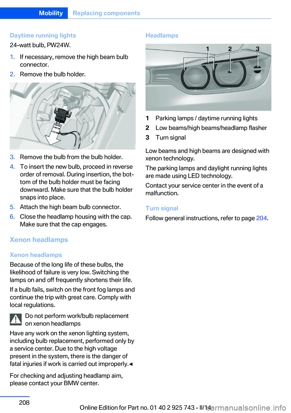
Headlamps1Parking lamps / daytime running lights2Low beams/high beams/headlamp flasher3Turn signal
Low beams and high beams are designed with
xenon technology.
The parking lamps and daylight running lights
are made using LED technology.
Contact your service center in the event of a
malfunction.
Turn signal
Follow general instructions, refer to page 204.
Seite 208MobilityReplacing components208
Online Edition for Part no. 01 40 2 925 743 - II/14
Page 209 of 242

21-watt bulb, PY21W1.In the wheel house, loosen the two brack‐
ets and remove the cover.2.If necessary, pull the inside trim of the
wheel house slightly inward. Turn the bulb
holder counterclockwise and remove.3.Press the bulb gently into the socket, turn
counterclockwise and remove.4.Install the new bulb and bulb holder in re‐
verse order of removal.5.Attach the cover to the wheel house.
Front fog lamps
Follow general instructions, refer to page 204.
35-watt bulb, H8.
1.Use the handle of the screwdriver from the
onboard vehicle tool kit to remove the
three wheel house panel screws, arrow 1.Carefully pull back the wheel house panel,
arrow 2.2.Pull off the bulb connector, arrow 1.
Turn the bulb, arrow 2.
Left side of vehicle: turn clockwise.
Right side of vehicle: turn counterclock‐
wise.
Remove the bulb.3.Insert the new bulb, connect the connector
and screw on the wheel house panel.
Turn signal in exterior mirror
Follow general instructions, refer to page 204.
The turn signals in the exterior mirrors feature
LED technology. Contact your service center
in the event of a malfunction.
Seite 209Replacing componentsMobility209
Online Edition for Part no. 01 40 2 925 743 - II/14