2014 BMW 320I XDRIVE lock
[x] Cancel search: lockPage 95 of 242

Protective action
Airbags are not triggered in every impact situa‐
tion, e.g., in less severe accidents or rear-end
collisions.
Information on how to ensure the optimal
protective effect of the airbags▷Keep at a distance from the airbags.▷Always grasp the steering wheel on the
steering wheel rim, holding your hands at
the 3 o'clock and 9 o'clock positions, to
keep the danger of injury to your hands or
arms as low as possible if the airbag is trig‐
gered.▷There should be no people, animals, or ob‐
jects between an airbag and a person.▷Do not use the cover of the front airbag on
the front passenger side as a storage area.▷Keep the dashboard and window on the
front passenger side clear, i.e. do not cover
with adhesive labels or coverings, and do
not attach holders such as for navigation
instruments and mobile phones.▷Make sure that the front passenger is sit‐
ting correctly, i.e., keeps his or her feet and
legs in the footwell; otherwise, leg injuries
can occur if the front airbag is triggered.▷Do not place slip covers, seat cushions or
other objects on the front passenger seat
that are not approved specifically for seats
with integrated side airbags.▷Do not hang pieces of clothing, such as
jackets, over the backrests.▷Make sure that occupants keep their heads
away from the side airbag and do not rest
against the head airbag; otherwise, injuries
can occur if the airbags are triggered.▷Do not remove the airbag restraint system.▷Do not remove the steering wheel.▷Do not apply adhesive materials to the air‐
bag cover panels, cover them or modify
them in any way.▷Never modify either the individual compo‐
nents or the wiring in the airbag system.
This also applies to steering wheel covers,
the dashboard, the seats, the roof pillars
and the sides of the headliner.◀
Even when all instructions are followed closely,
injury from contact with the airbags cannot be
ruled out in certain situations.
The ignition and inflation noise may lead to
short-term and, in most cases, temporary
hearing impairment in sensitive individuals.
In the case of a malfunction, deactivation
and after triggering of the airbags
Do not touch the individual components imme‐
diately after the system has been triggered;
otherwise, there is the danger of burns.
Only have the airbags checked, repaired or dis‐
mantled and the airbag generator scrapped by
the service center or a workshop that has the
necessary authorization for handling explo‐
sives.
Non-professional attempts to service the sys‐
tem could lead to failure in an emergency or
undesired triggering of the airbag, either of
which could result in injury.◀
Warnings and information on the airbags are
also found on the sun visors.
Functional readiness of the airbag
system
When the ignition is switched on, the
warning lamp in the instrument cluster
lights up briefly and thereby indicates
the operational readiness of the entire airbag
system and the belt tensioner.
Airbag system malfunctioning
▷Warning lamp does not come on when the
ignition is turned on.▷The warning lamp lights up continuously.Seite 95SafetyControls95
Online Edition for Part no. 01 40 2 925 743 - II/14
Page 114 of 242

Driving stability control systemsVehicle equipmentAll standard, country-specific and optional
equipment that is offered in the model series is
described in this chapter. Therefore, equip‐
ment is also described that is not available in a
vehicle, e. g., because of the selected optional
equipment or country variant. This also applies
for safety-related functions and systems.
Antilock Brake System ABS ABS prevents locking of the wheels during
braking.
The vehicle remains steerable even during full
brake applications, thus increasing active
safety.
ABS is operational every time you start the en‐
gine.
Brake assistant
When you apply the brakes rapidly, this system
automatically produces the maximum braking
force boost. This then reduces braking dis‐ tance to a minimum during full braking. This
system utilizes all of the benefits provided by ABS.
Do not reduce the pressure on the brake pedal
for the duration of the full braking.
DSC Dynamic Stability
Control
The concept
DSC prevents traction loss in the driving
wheels when driving away and accelerating.
DSC also recognizes unstable vehicle condi‐
tions, such as fishtailing or nose-diving. Sub‐ject to physical limits, DSC helps to keep the
vehicle on a steady course by reducing engine
speed and by applying brakes to the individual
wheels.
Adjust your driving style to the situation
An appropriate driving style is always the
responsibility of the driver.
The laws of physics cannot be repealed, even
with DSC.
Therefore, do not reduce the additional safety
margin by driving in a risky manner.◀
Indicator/warning lamps The indicator lamp flashes: DSC con‐
trols the drive forces and brake forces.
The indicator lamp lights up: DSC has
failed.
Deactivating DSC: DSC OFF
When DSC is deactivated, driving stability is
reduced during acceleration and when driving
in bends.
To increase vehicle stability, activate DSC
again as soon as possible.
Deactivating DSC Press and hold the button, but not lon‐
ger than approx. 10 seconds, until the
indicator lamp for DSC OFF lights up in the in‐
strument cluster and DSC OFF is displayed.
The DSC system is switched off.
Steering and, depending on the equipment,
the chassis are adjusted for sporty driving.
Activating DSC Press the button.Seite 114ControlsDriving stability control systems114
Online Edition for Part no. 01 40 2 925 743 - II/14
Page 143 of 242
▷LED off: outside air flows in continuously.▷LED on, recirculated-air mode: the supply
of outside air into the vehicle is perma‐
nently blocked.
Recirculated air mode switches off automati‐
cally at low external temperatures after a cer‐
tain amount of time in order to window fog‐
ging.
If the windows fog over, switch off recircu‐
lated-air mode and increase the air flow, if nec‐
essary.
Continuous recirculated-air mode
The recirculated-air mode should not be
used for an extended period of time, as the air
quality inside the vehicle deteriorates stead‐
ily.◀
Switching the system on/off Switching off Press the left button for the minimum
speed.
Switching on
Press any button except▷Rear window defroster.▷Seat heating.
Microfilter
In external and recirculated air mode the mi‐
crofilter filters dust and pollen out of the air.
This filter should be replaced during scheduled
maintenance, refer to page 202, of your vehi‐
cle.
Seite 143Climate controlControls143
Online Edition for Part no. 01 40 2 925 743 - II/14
Page 145 of 242

Air flow, air distribution, and temperature are
controlled automatically.
Depending on the selected temperature,
AUTO intensity program and outside influen‐
ces, the air is directed to the windshield, side
windows, upper body, and into the footwell.
The cooling function, refer to page 145, is
switched on automatically with the AUTO pro‐
gram.
At the same time, a condensation sensor con‐
trols the program so as to prevent window
condensation as much as possible.
Intensity of the AUTO program
With the AUTO program switched on, auto‐
matic control of the air flow and air distribution
can be adjusted.
Press the left or right side of the but‐
ton: decrease or increase the inten‐
sity.
The selected intensity is shown on the display
of the automatic climate control.
Maximum cooling Press the button.
The system is set to the lowest tem‐
perature, maximum air flow and air circulation
mode.
Air flows out of the vents for the upper body
region. The vents need to be open for this.
The function is available above an external
temperature of approx. 32 ℉/0 ℃ and with the
engine running.
The air flow can be adjusted when the program
is active.
Cooling function
The passenger compartment can only be
cooled with the engine running.
Press the button.The air is cooled and dehumidified and, de‐
pending on the temperature setting, warmed
again.
Depending on the weather, the windshield may
fog up briefly when the engine is started.
The cooling function is switched on automati‐
cally with the AUTO program.
When using the automatic climate control,
condensation water, refer to page 164, devel‐
ops that exits underneath the vehicle.
Automatic recirculated-air control/
recirculated-air mode
You can respond to unpleasant odors or pollu‐
tants in the immediate environment by tempo‐
rarily suspending the supply of outside air. The
system then recirculates the air currently
within the vehicle.
Press the button repeatedly to select
an operating mode:▷LEDs off: outside air flows in continuously.▷Left LED on, automatic recirculated-air
control: a sensor detects pollutants in the
outside air and controls the shutoff auto‐
matically.▷Right LED on, recirculated-air mode: the
supply of outside air into the vehicle is per‐
manently blocked.
Recirculated air mode switches off automati‐
cally at low external temperatures after a cer‐
tain amount of time in order to window fog‐
ging.
If the windows are fogged over, switch off the
recirculated-air mode and press the AUTO
button to utilize the condensation sensor.
Make sure that air can flow onto the wind‐
shield.
Continuous recirculated-air mode
The recirculated-air mode should not be
used for an extended period of time, as the air
quality inside the vehicle deteriorates stead‐
ily.◀
Seite 145Climate controlControls145
Online Edition for Part no. 01 40 2 925 743 - II/14
Page 154 of 242
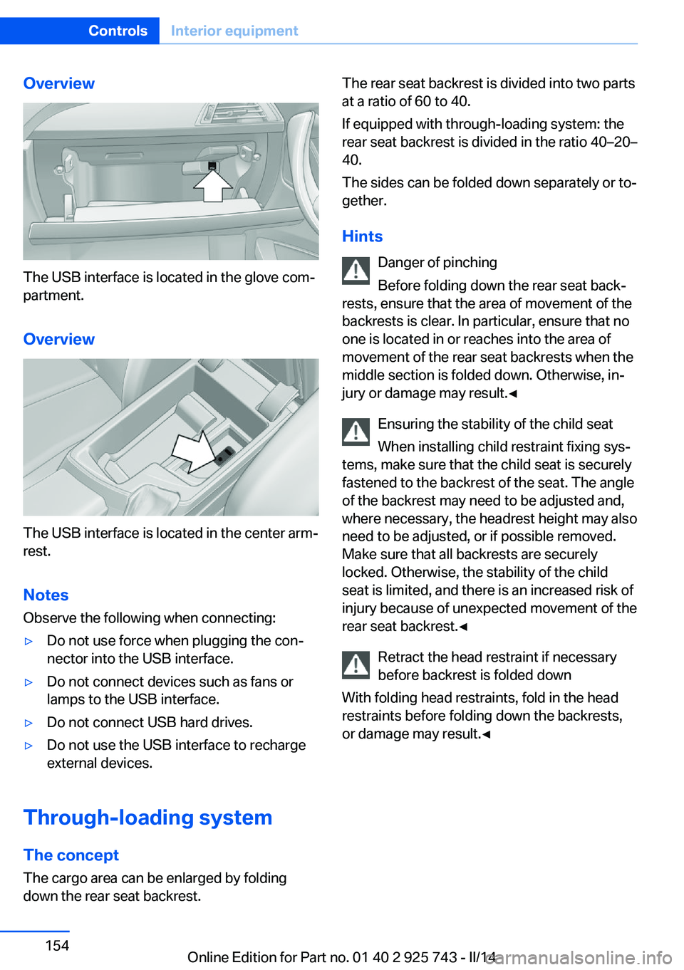
Overview
The USB interface is located in the glove com‐
partment.
Overview
The USB interface is located in the center arm‐
rest.
Notes Observe the following when connecting:
▷Do not use force when plugging the con‐
nector into the USB interface.▷Do not connect devices such as fans or
lamps to the USB interface.▷Do not connect USB hard drives.▷Do not use the USB interface to recharge
external devices.
Through-loading system
The concept The cargo area can be enlarged by folding
down the rear seat backrest.
The rear seat backrest is divided into two parts at a ratio of 60 to 40.
If equipped with through-loading system: the
rear seat backrest is divided in the ratio 40–20– 40.
The sides can be folded down separately or to‐
gether.
Hints Danger of pinching
Before folding down the rear seat back‐
rests, ensure that the area of movement of the
backrests is clear. In particular, ensure that no
one is located in or reaches into the area of
movement of the rear seat backrests when the
middle section is folded down. Otherwise, in‐
jury or damage may result.◀
Ensuring the stability of the child seat
When installing child restraint fixing sys‐
tems, make sure that the child seat is securely
fastened to the backrest of the seat. The angle
of the backrest may need to be adjusted and,
where necessary, the headrest height may also
need to be adjusted, or if possible removed.
Make sure that all backrests are securely
locked. Otherwise, the stability of the child
seat is limited, and there is an increased risk of
injury because of unexpected movement of the
rear seat backrest.◀
Retract the head restraint if necessary
before backrest is folded down
With folding head restraints, fold in the head
restraints before folding down the backrests,
or damage may result.◀Seite 154ControlsInterior equipment154
Online Edition for Part no. 01 40 2 925 743 - II/14
Page 155 of 242
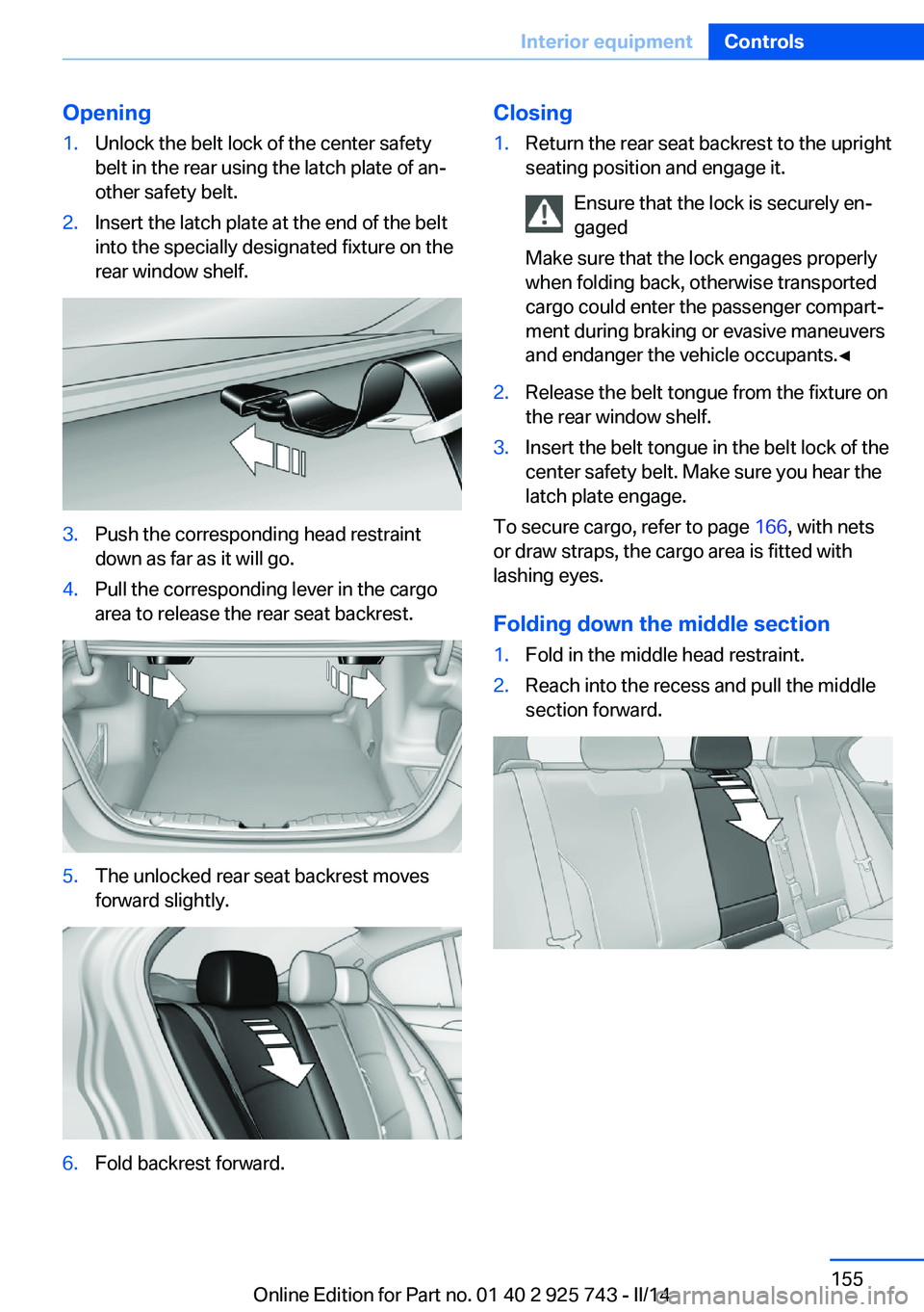
Opening1.Unlock the belt lock of the center safety
belt in the rear using the latch plate of an‐
other safety belt.2.Insert the latch plate at the end of the belt
into the specially designated fixture on the
rear window shelf.3.Push the corresponding head restraint
down as far as it will go.4.Pull the corresponding lever in the cargo
area to release the rear seat backrest.5.The unlocked rear seat backrest moves
forward slightly.6.Fold backrest forward.Closing1.Return the rear seat backrest to the upright
seating position and engage it.
Ensure that the lock is securely en‐
gaged
Make sure that the lock engages properly
when folding back, otherwise transported
cargo could enter the passenger compart‐
ment during braking or evasive maneuvers
and endanger the vehicle occupants.◀2.Release the belt tongue from the fixture on
the rear window shelf.3.Insert the belt tongue in the belt lock of the
center safety belt. Make sure you hear the
latch plate engage.
To secure cargo, refer to page 166, with nets
or draw straps, the cargo area is fitted with
lashing eyes.
Folding down the middle section
1.Fold in the middle head restraint.2.Reach into the recess and pull the middle
section forward.Seite 155Interior equipmentControls155
Online Edition for Part no. 01 40 2 925 743 - II/14
Page 157 of 242
LockingThe glove compartment can be locked with an
integrated key to separately secure the trunk
lid, refer to page 38, for example.
This prevents access to the glove compart‐
ment and to the cargo area.
After the glove compartment is locked, the re‐
mote control can be handed over, such as at a
hotel, without the integrated key.
Driver's side
Note Close the glove compartment again im‐
mediately
Close the glove compartment immediately af‐
ter use while driving; otherwise, injury may oc‐
cur during accidents.◀
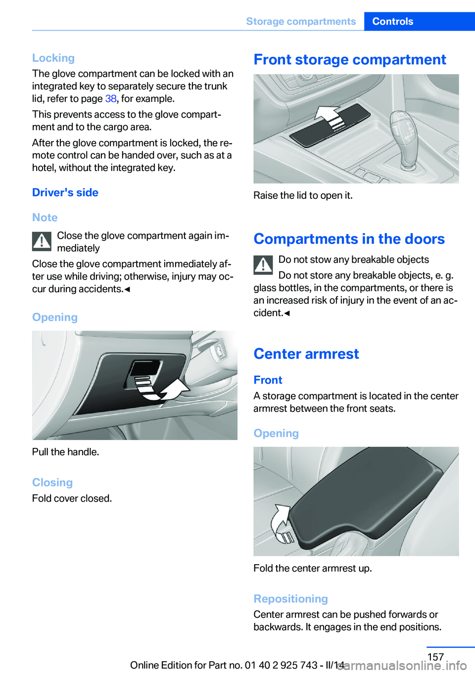
Opening
Pull the handle.
ClosingFold cover closed.
Front storage compartment
Raise the lid to open it.
Compartments in the doors Do not stow any breakable objects
Do not store any breakable objects, e. g.
glass bottles, in the compartments, or there is
an increased risk of injury in the event of an ac‐
cident.◀
Center armrest
Front A storage compartment is located in the center
armrest between the front seats.
Opening
Fold the center armrest up.
Repositioning
Center armrest can be pushed forwards or
backwards. It engages in the end positions.
Seite 157Storage compartmentsControls157
Online Edition for Part no. 01 40 2 925 743 - II/14
Page 178 of 242
RefuelingVehicle equipment
All standard, country-specific and optional
equipment that is offered in the model series is
described in this chapter. Therefore, equip‐
ment is also described that is not available in a
vehicle, e. g., because of the selected optional
equipment or country variant. This also applies
for safety-related functions and systems.
Hints Refuel promptly
Refuel no later than at a range of
30 miles/50 km, or operation of the engine is
not ensured and damage may occur.◀
Diesel engines The filler neck is designed for refueling at die‐
sel fuel pumps.
Fuel cap
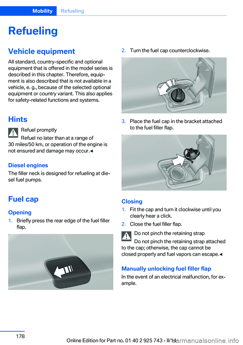
Opening1.Briefly press the rear edge of the fuel filler
flap.2.Turn the fuel cap counterclockwise.3.Place the fuel cap in the bracket attached
to the fuel filler flap.
Closing
1.Fit the cap and turn it clockwise until you
clearly hear a click.2.Close the fuel filler flap.
Do not pinch the retaining strap
Do not pinch the retaining strap attached
to the cap; otherwise, the cap cannot be
closed properly and fuel vapors can escape.◀
Manually unlocking fuel filler flap In the event of an electrical malfunction, for ex‐
ample.
Seite 178MobilityRefueling178
Online Edition for Part no. 01 40 2 925 743 - II/14