2014 BMW 3 SERIES SPORTS WAGON Lights
[x] Cancel search: LightsPage 139 of 253
Volume
The volume of the PDC signal tone can be ad‐
justed similar to the sound and volume set‐
tings of the radio.
Settings are stored for the profile currently in
use.
Visual warning
The approach of the vehicle to an object can
be shown on the Control Display. Objects that
are farther away are already displayed on the
Control Display before a signal sounds.
A display appears as soon as Park Distance
Control (PDC) is activated.
The range of the sensors is represented in the
colors green, yellow and red.
When the image of the rearview camera is dis‐
played, the reel can be made to PDC:
"Rear view camera"
System limits
Limits of ultrasonic measurement
Ultrasonic measuring might not function under
the following circumstances:
▷For small children and animals.▷For persons with certain clothing, e.g.
coats.▷With external interference of the ultra‐
sound, e.g. from passing vehicles or loud
machines.▷When sensors are dirty, iced over, dam‐
aged or out of position.▷Under certain weather conditions such as
high relative humidity, rain, snowfall, ex‐
treme heat or strong wind.▷With tow bars and trailer couplings of other
vehicles.▷With thin or wedge-shaped objects.▷With moving objects.▷With elevated, protruding objects such as
ledges or cargo.▷With objects with corners and sharp edges.▷With objects with a fine surface structure
such as fences.▷For objects with porous surfaces.
Low objects already displayed, e.g., curbs, can
move into the blind area of the sensors before
or after a continuous tone sounds.
False warnings
PDC may issue a warning under the following conditions even though there is no obstacle
within the detection range:
▷In heavy rain.▷When sensors are very dirty or covered
with ice.▷When sensors are covered in snow.▷On rough road surfaces.▷On uneven surfaces, such as speed
bumps.▷In large buildings with right angles and
smooth walls, e.g., in underground ga‐
rages.▷Through heavy pollution.▷Due to other ultrasound sources, e.g.,
sweeping machines, high pressure steam
cleaners or neon lights.
The malfunction is signaled by a continu‐
ous tone alternating between the front and
rear speakers. As soon as the malfunction
due to other ultrasound sources is no lon‐
ger present, the system is again fully func‐
tional.
Malfunction
A Check Control message is displayed.
The range of the sensors is shown as a shaded
area on the Control Display.
PDC has failed. Have the system checked.
To ensure full functionality:
Seite 135Driving comfortControls135
Online Edition for Part no. 01 40 2 956 752 - X/14
Page 141 of 253
Switching on/off manuallyPress button.▷On: the LED lights up.▷Off: the LED goes out.
The PDC is shown on the Control Display.
Switching the view via iDrive With PDC activated or Top View switched on:
"Rear view camera"
The rearview camera image is displayed.
Display on the Control Display
Functional requirement
▷The rearview camera is switched on.▷The tailgate is fully closed.
Activating assistance functions
More than one assistance function can be ac‐
tive at the same time.
▷Parking aid lines
"Parking aid lines"
Lanes and turning radius are indicated.
▷Obstacle marking
"Obstacle marking"
Spatially-shaped markings are displayed.
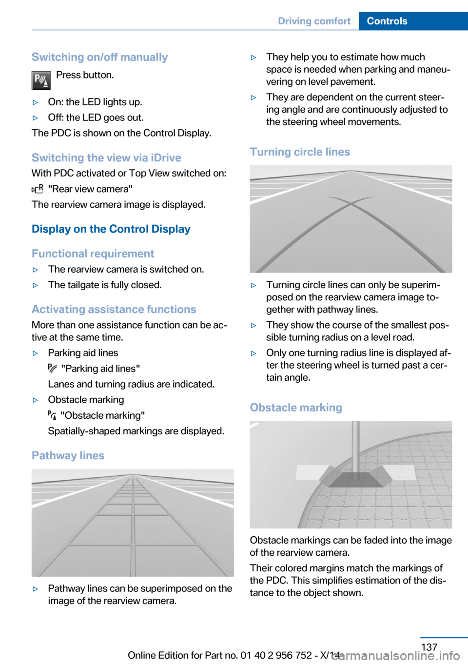
Pathway lines
▷Pathway lines can be superimposed on the
image of the rearview camera.▷They help you to estimate how much
space is needed when parking and maneu‐
vering on level pavement.▷They are dependent on the current steer‐
ing angle and are continuously adjusted to
the steering wheel movements.
Turning circle lines
▷Turning circle lines can only be superim‐
posed on the rearview camera image to‐
gether with pathway lines.▷They show the course of the smallest pos‐
sible turning radius on a level road.▷Only one turning radius line is displayed af‐
ter the steering wheel is turned past a cer‐
tain angle.
Obstacle marking
Obstacle markings can be faded into the image
of the rearview camera.
Their colored margins match the markings of
the PDC. This simplifies estimation of the dis‐
tance to the object shown.
Seite 137Driving comfortControls137
Online Edition for Part no. 01 40 2 956 752 - X/14
Page 144 of 253
General information
The image is lidtured by two cameras
integrated in the exterior mirrors and by the
rearview camera.
The range is at least 7 ft/2 m to the side and
rear.
In this way, obstacles up to the height of the
exterior mirrors are detected early.
Hints Check the traffic situation as well
Check the traffic situation around the ve‐
hicle with your own eyes. Otherwise, an acci‐
dent could result from road users or objects
that are not lidtured by the camera.◀
At a glance
Button in the vehicle
Top View
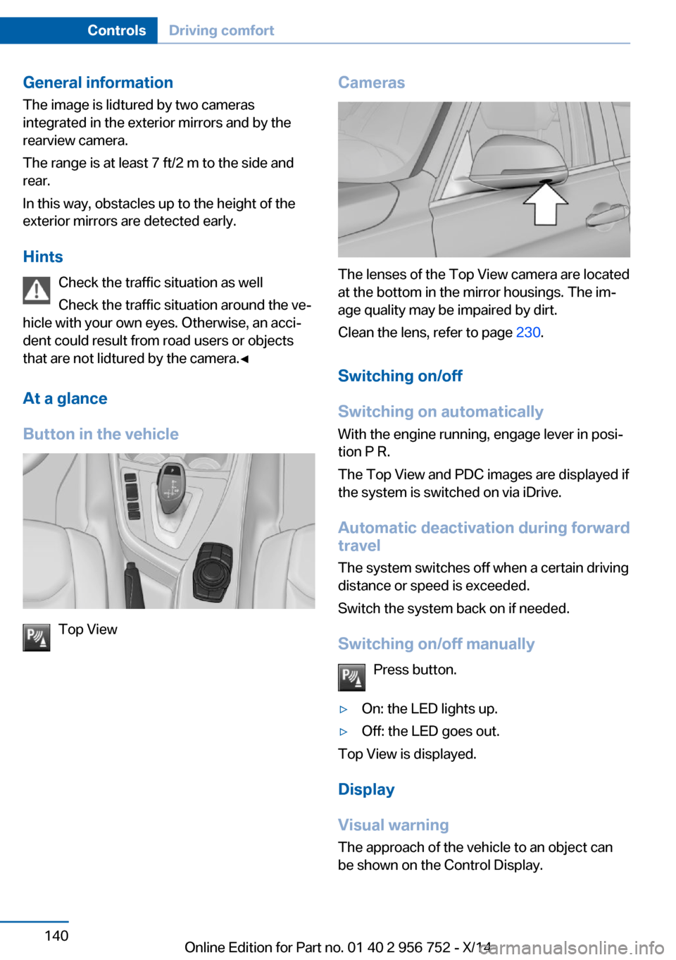
Cameras
The lenses of the Top View camera are located
at the bottom in the mirror housings. The im‐
age quality may be impaired by dirt.
Clean the lens, refer to page 230.
Switching on/off
Switching on automatically With the engine running, engage lever in posi‐
tion P R.
The Top View and PDC images are displayed if
the system is switched on via iDrive.
Automatic deactivation during forward
travel
The system switches off when a certain driving
distance or speed is exceeded.
Switch the system back on if needed.
Switching on/off manually Press button.
▷On: the LED lights up.▷Off: the LED goes out.
Top View is displayed.
Display
Visual warning
The approach of the vehicle to an object can
be shown on the Control Display.
Seite 140ControlsDriving comfort140
Online Edition for Part no. 01 40 2 956 752 - X/14
Page 147 of 253
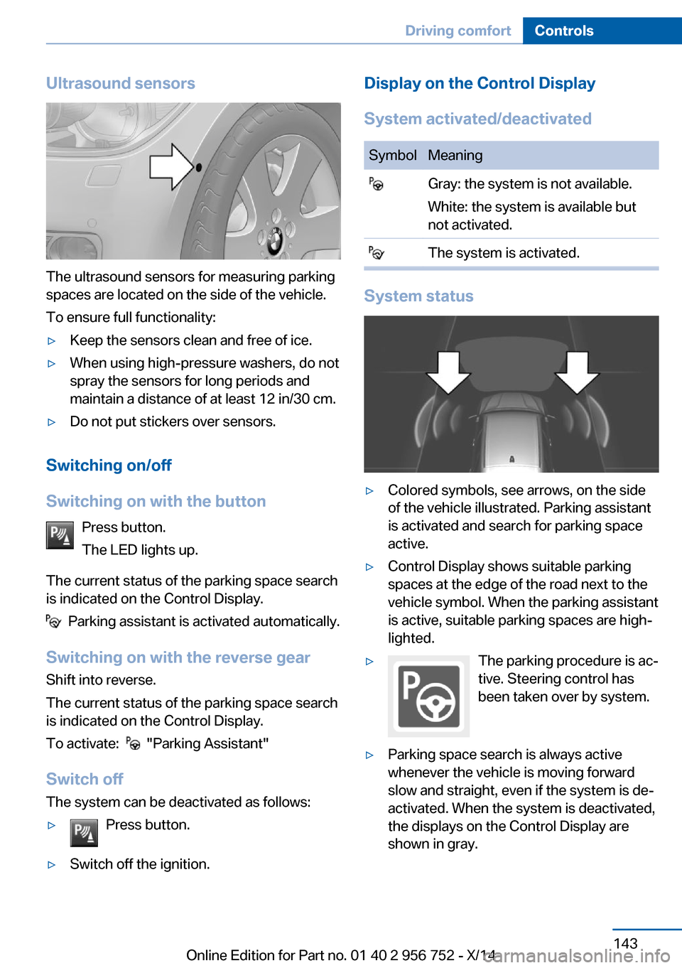
Ultrasound sensors
The ultrasound sensors for measuring parking
spaces are located on the side of the vehicle.
To ensure full functionality:
▷Keep the sensors clean and free of ice.▷When using high-pressure washers, do not
spray the sensors for long periods and
maintain a distance of at least 12 in/30 cm.▷Do not put stickers over sensors.
Switching on/off
Switching on with the button Press button.
The LED lights up.
The current status of the parking space search
is indicated on the Control Display.
Parking assistant is activated automatically.
Switching on with the reverse gear
Shift into reverse.
The current status of the parking space search
is indicated on the Control Display.
To activate:
"Parking Assistant"
Switch off
The system can be deactivated as follows:
▷Press button.▷Switch off the ignition.Display on the Control Display
System activated/deactivatedSymbolMeaning Gray: the system is not available.
White: the system is available but
not activated. The system is activated.
System status
▷Colored symbols, see arrows, on the side
of the vehicle illustrated. Parking assistant
is activated and search for parking space
active.▷Control Display shows suitable parking
spaces at the edge of the road next to the
vehicle symbol. When the parking assistant
is active, suitable parking spaces are high‐
lighted.▷The parking procedure is ac‐
tive. Steering control has
been taken over by system.▷Parking space search is always active
whenever the vehicle is moving forward
slow and straight, even if the system is de‐
activated. When the system is deactivated,
the displays on the Control Display are
shown in gray.Seite 143Driving comfortControls143
Online Edition for Part no. 01 40 2 956 752 - X/14
Page 156 of 253
Parked-car ventilation
The concept The parked-car ventilation ventilates the vehi‐
cle interior and lowers its temperature, if
needed.
The system can be switched on and off at any
external temperature, either directly or by us‐
ing two preset reel-on times. It remains
switched on for 30 minutes.
Open the vents to allow air to flow out.
Switching on/off directly
On the Control Display:1."Settings"2."Climate"3."Activate comf. ventilation"
The symbol on the automatic climate con‐
trol flashes if the system is switched on.
Preselecting the reel-on time
On the Control Display:
1."Settings"2."Climate"3."Timer 1:" or "Timer 2:"4.Set the desired time.
Activating the reel-on time
On the Control Display:
1."Settings"2."Climate"3."Activate timer 1" or "Activate timer 2"
The symbol on the automatic climate con‐
trol lights up when the reel-on time is acti‐
vated.
The symbol on the automatic climate con‐
trol flashes when the system has been
switched on.
The system will only be switched on within the
next 24 hours. After that, it needs to be reacti‐
vated.Seite 152ControlsClimate control152
Online Edition for Part no. 01 40 2 956 752 - X/14
Page 163 of 253
▷Do not connect devices such as fans or
lights to the USB interface.▷Do not connect USB hard drives.▷Do not use the USB interface for recharg‐
ing external devices.
Without telephone: overview
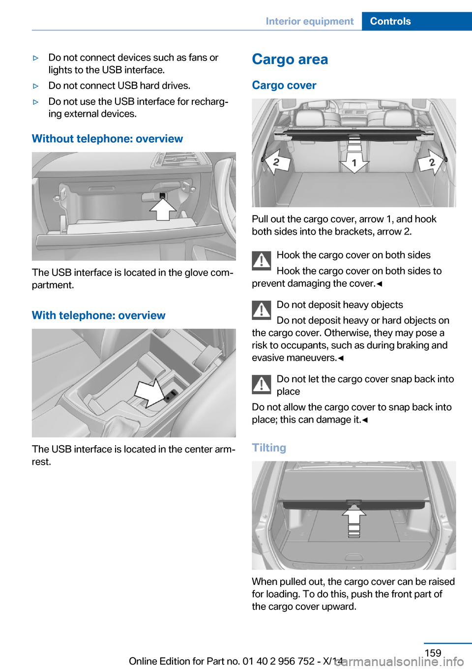
The USB interface is located in the glove com‐
partment.
With telephone: overview
The USB interface is located in the center arm‐
rest.
Cargo area
Cargo cover
Pull out the cargo cover, arrow 1, and hook
both sides into the brackets, arrow 2.
Hook the cargo cover on both sides
Hook the cargo cover on both sides to
prevent damaging the cover.◀
Do not deposit heavy objects
Do not deposit heavy or hard objects on
the cargo cover. Otherwise, they may pose a
risk to occupants, such as during braking and
evasive maneuvers.◀
Do not let the cargo cover snap back into
place
Do not allow the cargo cover to snap back into
place; this can damage it.◀
Tilting
When pulled out, the cargo cover can be raised
for loading. To do this, push the front part of
the cargo cover upward.
Seite 159Interior equipmentControls159
Online Edition for Part no. 01 40 2 956 752 - X/14
Page 181 of 253
Avoid high engine speeds
As a rule: driving at low engine speeds lowers
fuel consumption and reduces wear.
Use 1st gear to get the vehicle moving. Start‐
ing with the 2nd gear, accelerate rapidly. When
accelerating, shift up before reaching high en‐
gine speeds.
When you reach the desired speed, shift into
the highest applicable gear and drive with the
engine speed as low as possible and at a con‐
stant speed.
If necessary, observe the gear shift indicator of
the vehicle, refer to page 85.
Use coasting
When approaching a red light, take your foot
off the accelerator and let the vehicle coast to
a halt.
For going downhill take your foot off the accel‐
erator and let the vehicle roll.
The flow of fuel is interrupted while coasting.
Switch off the engine during longer stops
Switch off the engine during longer stops, e.g.,
at traffic lights, railroad crossings or in traffic
congestion.
Auto Start/Stop function The Auto Start/Stop function of your vehicle
automatically switches off the engine during a
stop.
If the engine is switched off and then restarted
rather than leaving the engine running con‐
stantly, fuel consumption and emissions are
reduced. Savings can begin within a few sec‐
onds of switching off the engine.
In addition, fuel consumption is also deter‐
mined by other factors, such as driving style,road conditions, maintenance or environmental
factors.
Switch off any functions that
are not currently needed
Functions such as seat heating and the rear
window defroster require a lot of energy and
reduce the range, especially in city and stop-
and-go traffic.
Reel off these functions if they are not needed. The ECO PRO driving program supports the
energy conserving use of comfort features.
These functions are automatically deactivated
partially or completely.
Have maintenance carriedout
Have vehicles maintained regularly to achieve
optimal vehicle efficiency and operating life.
The maintenance should be carried out by
your service center.
Also note the BMW Maintenance System, refer
to page 207.
ECO PRO
The concept ECO PRO supports a driving style that saves
on fuel consumption. For this purpose, the en‐
gine control and comfort features, e. g. the cli‐
mate control output, are adjusted.
Under certain conditions the engine is auto‐
matically decoupled from the transmission in
the D selector lever position. The vehicle con‐
tinues traveling with the engine idling to re‐
duce fuel consumption. Selector lever position
D remains engaged.
In addition, context-sensitive instructions are
displayed to assist with an optimized fuel con‐
sumption driving style.Seite 177Saving fuelDriving tips177
Online Edition for Part no. 01 40 2 956 752 - X/14
Page 206 of 253
Hood
Hints Working in the engine compartment
Never attempt to perform any service or
repair operations on your vehicle without the
necessary professional technical training.
If you are unfamiliar with the statutory guide‐
lines, have any work on the vehicle performed
only by a service center.
If work is not carried out properly, there is a
danger of subsequent damage and related
safety hazards.◀
Never reach into the engine compart‐
ment
Never reach into spaces or gaps in the engine
compartment; otherwise, there is a risk of in‐
jury, e.g., from rotating or hot parts.◀
Fold down wiper arm
Before opening the hood, ensure that the
wiper arms are against the windshield, or this
may result in damage.◀
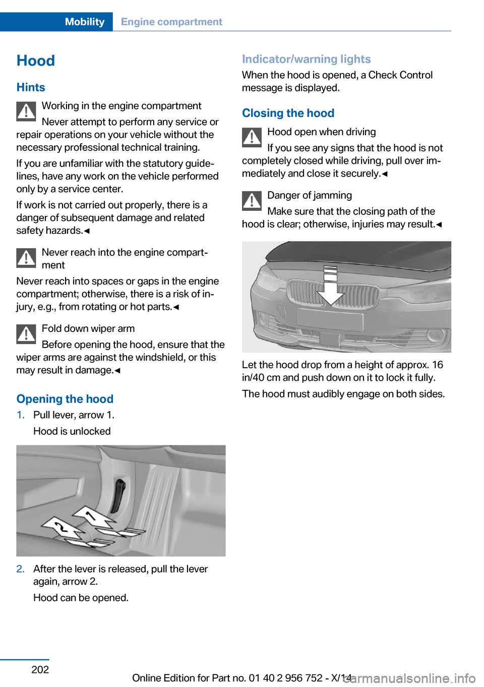
Opening the hood1.Pull lever, arrow 1.
Hood is unlocked2.After the lever is released, pull the lever
again, arrow 2.
Hood can be opened.Indicator/warning lights
When the hood is opened, a Check Control
message is displayed.
Closing the hood Hood open when driving
If you see any signs that the hood is not
completely closed while driving, pull over im‐
mediately and close it securely.◀
Danger of jamming
Make sure that the closing path of the
hood is clear; otherwise, injuries may result.◀
Let the hood drop from a height of approx. 16
in/40 cm and push down on it to lock it fully.
The hood must audibly engage on both sides.
Seite 202MobilityEngine compartment202
Online Edition for Part no. 01 40 2 956 752 - X/14