2014 BMW 3 SERIES SPORTS WAGON warning
[x] Cancel search: warningPage 133 of 253
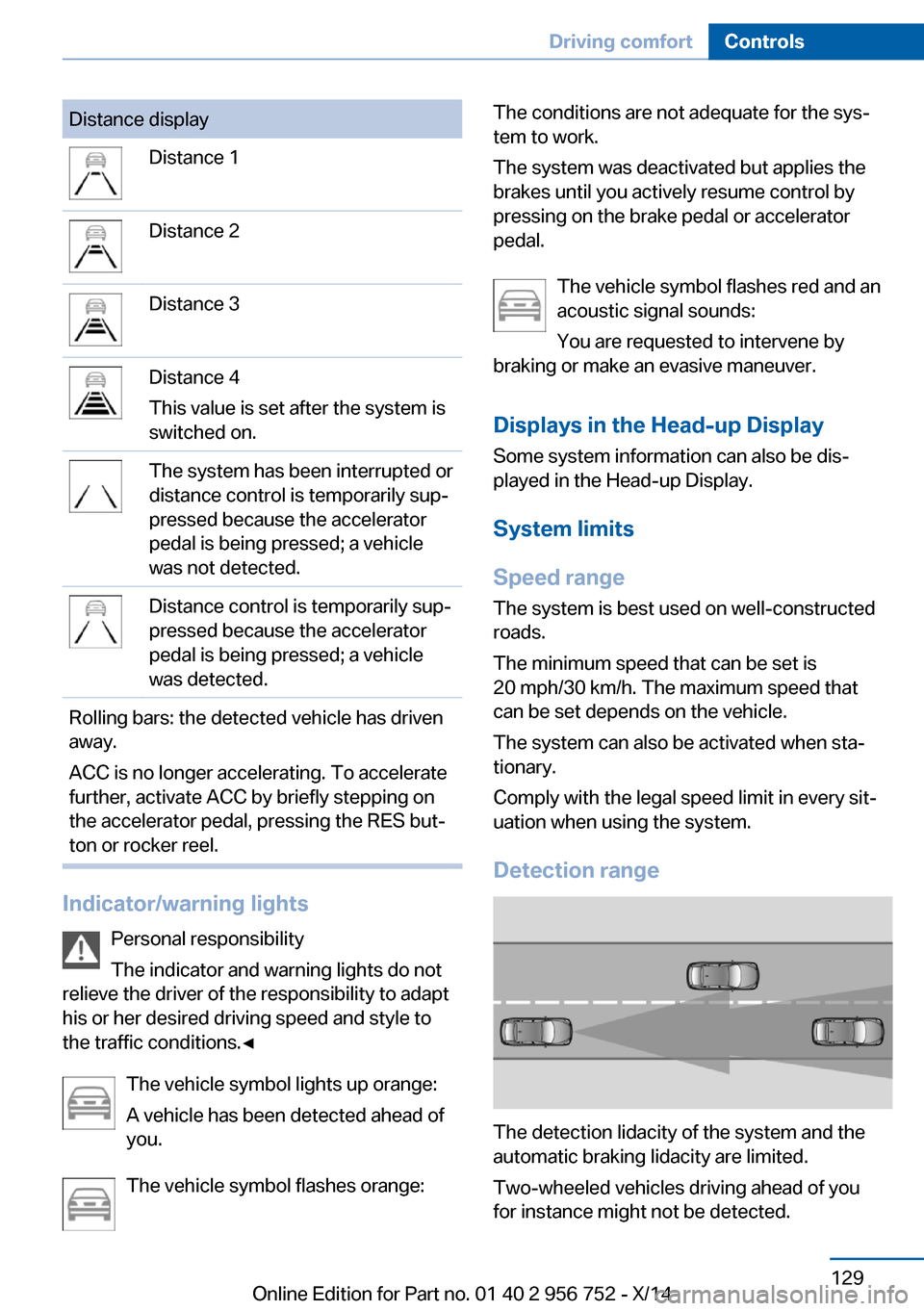
Distance displayDistance 1Distance 2Distance 3Distance 4
This value is set after the system is
switched on.The system has been interrupted or
distance control is temporarily sup‐
pressed because the accelerator
pedal is being pressed; a vehicle
was not detected.Distance control is temporarily sup‐
pressed because the accelerator
pedal is being pressed; a vehicle
was detected.Rolling bars: the detected vehicle has driven
away.
ACC is no longer accelerating. To accelerate
further, activate ACC by briefly stepping on
the accelerator pedal, pressing the RES but‐
ton or rocker reel.
Indicator/warning lights
Personal responsibility
The indicator and warning lights do not
relieve the driver of the responsibility to adapt
his or her desired driving speed and style to
the traffic conditions.◀
The vehicle symbol lights up orange:
A vehicle has been detected ahead of
you.
The vehicle symbol flashes orange:
The conditions are not adequate for the sys‐
tem to work.
The system was deactivated but applies the
brakes until you actively resume control by
pressing on the brake pedal or accelerator
pedal.
The vehicle symbol flashes red and an
acoustic signal sounds:
You are requested to intervene by
braking or make an evasive maneuver.
Displays in the Head-up Display Some system information can also be dis‐
played in the Head-up Display.
System limits
Speed range The system is best used on well-constructed
roads.
The minimum speed that can be set is
20 mph/30 km/h. The maximum speed that
can be set depends on the vehicle.
The system can also be activated when sta‐
tionary.
Comply with the legal speed limit in every sit‐
uation when using the system.
Detection range
The detection lidacity of the system and the
automatic braking lidacity are limited.
Two-wheeled vehicles driving ahead of you
for instance might not be detected.
Seite 129Driving comfortControls129
Online Edition for Part no. 01 40 2 956 752 - X/14
Page 134 of 253
Limited detection potential
Because of the limited possible detec‐
tion, you should be alert at all times so that you
can intervene if needed; otherwise, there is the
risk of an accident.◀
Deceleration
The system does not decelerate when a sta‐
tionary obstacle is located in the same lane,
e.g., a vehicle at a red traffic light or at the end
of traffic congestion.
The system also does not respond to:▷Pedestrians or similar slow-moving road
users.▷Red traffic lights.▷Stationary objects.▷Cross traffic.▷Oncoming traffic.
No warnings
A warning may not be issued when ap‐
proaching a stationary or very slow-moving ob‐
stacle. You must react yourself; otherwise,
there is the risk of an accident.◀
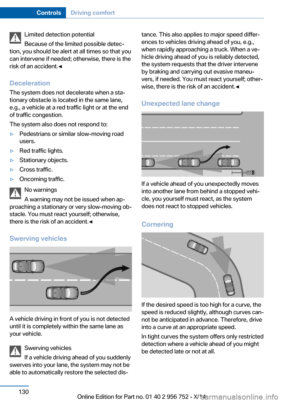
Swerving vehicles
A vehicle driving in front of you is not detected
until it is completely within the same lane as
your vehicle.
Swerving vehicles
If a vehicle driving ahead of you suddenly
swerves into your lane, the system may not be
able to automatically restore the selected dis‐
tance. This also applies to major speed differ‐
ences to vehicles driving ahead of you, e.g.,
when rapidly approaching a truck. When a ve‐
hicle driving ahead of you is reliably detected,
the system requests that the driver intervene
by braking and carrying out evasive maneu‐
vers, if needed. You must react yourself; other‐
wise, there is the risk of an accident.◀
Unexpected lane change
If a vehicle ahead of you unexpectedly moves
into another lane from behind a stopped vehi‐
cle, you yourself must react, as the system
does not react to stopped vehicles.
Cornering
If the desired speed is too high for a curve, the
speed is reduced slightly, although curves can‐
not be anticipated in advance. Therefore, drive
into a curve at an appropriate speed.
In tight curves the system offers only restricted
detection where a vehicle ahead of you might
be detected late or not at all.
Seite 130ControlsDriving comfort130
Online Edition for Part no. 01 40 2 956 752 - X/14
Page 137 of 253
When cruise control is maintained or stored,
DSC Dynamic Stability Control will be turned
on if needed.
Changing the speed
Press the rocker reel up or down repeatedly
until the desired speed is set.
If active, the displayed speed is stored and the
vehicle reaches the stored speed when the
road is clear.▷Each time the rocker reel is pressed to the
point of resistance, the desired speed in‐
creases or decreases by approx.
1 mph/1 km/h.▷Each time the rocker reel is pressed past
the point of resistance, the desired speed
increases or decreases by a maximum of
5 mph/10 km/h.
The maximum speed that can be set de‐
pends on the vehicle.▷Pressing the rocker reel to the resistance
point and holding it accelerates or deceler‐
ates the vehicle without requiring pressure
on the accelerator pedal.
After the rocker reel is released, the vehicle
maintains its final speed. Pressing the reel
beyond the resistance point causes the ve‐
hicle to accelerate more rapidly.
Resuming the desired speed
Press button.
The stored speed is reached and maintained. Displays in the instrument cluster
Indicator lamp Depending on how the vehicle is equip‐
ped, the indicator lamp in the instru‐
ment cluster indicates whether the sys‐
tem is switched on.
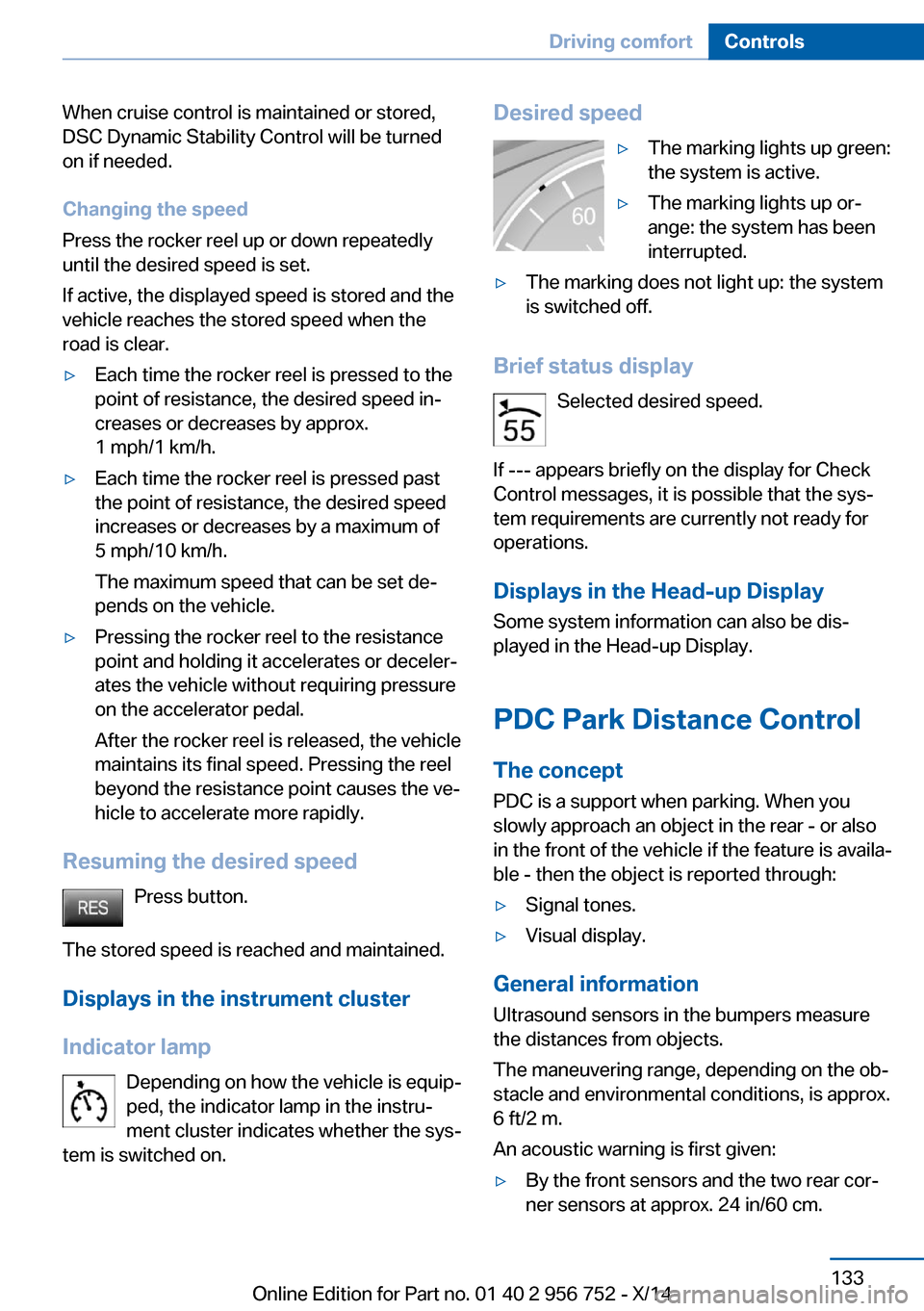
Desired speed▷The marking lights up green:
the system is active.▷The marking lights up or‐
ange: the system has been
interrupted.▷The marking does not light up: the system
is switched off.
Brief status display
Selected desired speed.
If --- appears briefly on the display for Check
Control messages, it is possible that the sys‐
tem requirements are currently not ready for
operations.
Displays in the Head-up Display Some system information can also be dis‐played in the Head-up Display.
PDC Park Distance Control
The concept PDC is a support when parking. When you
slowly approach an object in the rear - or also
in the front of the vehicle if the feature is availa‐
ble - then the object is reported through:
▷Signal tones.▷Visual display.
General information
Ultrasound sensors in the bumpers measure
the distances from objects.
The maneuvering range, depending on the ob‐
stacle and environmental conditions, is approx.
6 ft/2 m.
An acoustic warning is first given:
▷By the front sensors and the two rear cor‐
ner sensors at approx. 24 in/60 cm.Seite 133Driving comfortControls133
Online Edition for Part no. 01 40 2 956 752 - X/14
Page 138 of 253
▷By the rear middle sensors at approx.
5 ft/1.50 m.
To ensure full functionality:
▷Do not cover sensors, e.g., with stickers,
bicycle racks and the like.▷Keep the sensors clean and free of ice.▷When using high-pressure washers, do not
spray the sensors for long periods and
maintain a distance of at least 12 in/30 cm.
Hints
Personal responsibility
Even an active system does not relieve
the driver from personal responsibility while
driving.
Technically the system has its limits, it cannot
independently react to all traffic situations.
Monitor your driving, be on the alert, observe
the vehicle surroundings and other traffic and
react when needed - risk of accident.◀
Avoid driving fast with PDC
Avoid approaching an object too fast.
Avoid driving off fast while PDC is not yet ac‐
tive.
For technical reasons, the system may other‐
wise be too late in issuing a warning.◀
At a glance
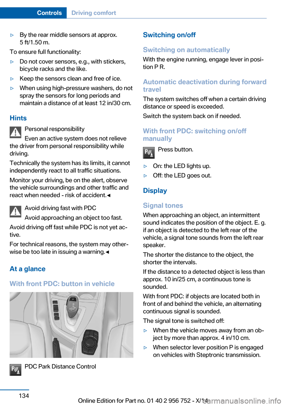
With front PDC: button in vehicle
PDC Park Distance Control
Switching on/off
Switching on automatically With the engine running, engage lever in posi‐
tion P R.
Automatic deactivation during forward travel
The system switches off when a certain driving
distance or speed is exceeded.
Switch the system back on if needed.
With front PDC: switching on/off
manually
Press button.▷On: the LED lights up.▷Off: the LED goes out.
Display
Signal tones When approaching an object, an intermittent
sound indicates the position of the object. E. g.
if an object is detected to the left rear of the
vehicle, a signal tone sounds from the left rear
speaker.
The shorter the distance to the object, the shorter the intervals.
If the distance to a detected object is less than
approx. 10 in/25 cm, a continuous tone is
sounded.
With front PDC: if objects are located both in
front of and behind the vehicle, an alternating
continuous signal is sounded.
The signal tone is switched off:
▷When the vehicle moves away from an ob‐
ject by more than approx. 4 in/10 cm.▷When selector lever position P is engaged
on vehicles with Steptronic transmission.Seite 134ControlsDriving comfort134
Online Edition for Part no. 01 40 2 956 752 - X/14
Page 139 of 253
Volume
The volume of the PDC signal tone can be ad‐
justed similar to the sound and volume set‐
tings of the radio.
Settings are stored for the profile currently in
use.
Visual warning
The approach of the vehicle to an object can
be shown on the Control Display. Objects that
are farther away are already displayed on the
Control Display before a signal sounds.
A display appears as soon as Park Distance
Control (PDC) is activated.
The range of the sensors is represented in the
colors green, yellow and red.
When the image of the rearview camera is dis‐
played, the reel can be made to PDC:
"Rear view camera"
System limits
Limits of ultrasonic measurement
Ultrasonic measuring might not function under
the following circumstances:
▷For small children and animals.▷For persons with certain clothing, e.g.
coats.▷With external interference of the ultra‐
sound, e.g. from passing vehicles or loud
machines.▷When sensors are dirty, iced over, dam‐
aged or out of position.▷Under certain weather conditions such as
high relative humidity, rain, snowfall, ex‐
treme heat or strong wind.▷With tow bars and trailer couplings of other
vehicles.▷With thin or wedge-shaped objects.▷With moving objects.▷With elevated, protruding objects such as
ledges or cargo.▷With objects with corners and sharp edges.▷With objects with a fine surface structure
such as fences.▷For objects with porous surfaces.
Low objects already displayed, e.g., curbs, can
move into the blind area of the sensors before
or after a continuous tone sounds.
False warnings
PDC may issue a warning under the following conditions even though there is no obstacle
within the detection range:
▷In heavy rain.▷When sensors are very dirty or covered
with ice.▷When sensors are covered in snow.▷On rough road surfaces.▷On uneven surfaces, such as speed
bumps.▷In large buildings with right angles and
smooth walls, e.g., in underground ga‐
rages.▷Through heavy pollution.▷Due to other ultrasound sources, e.g.,
sweeping machines, high pressure steam
cleaners or neon lights.
The malfunction is signaled by a continu‐
ous tone alternating between the front and
rear speakers. As soon as the malfunction
due to other ultrasound sources is no lon‐
ger present, the system is again fully func‐
tional.
Malfunction
A Check Control message is displayed.
The range of the sensors is shown as a shaded
area on the Control Display.
PDC has failed. Have the system checked.
To ensure full functionality:
Seite 135Driving comfortControls135
Online Edition for Part no. 01 40 2 956 752 - X/14
Page 144 of 253
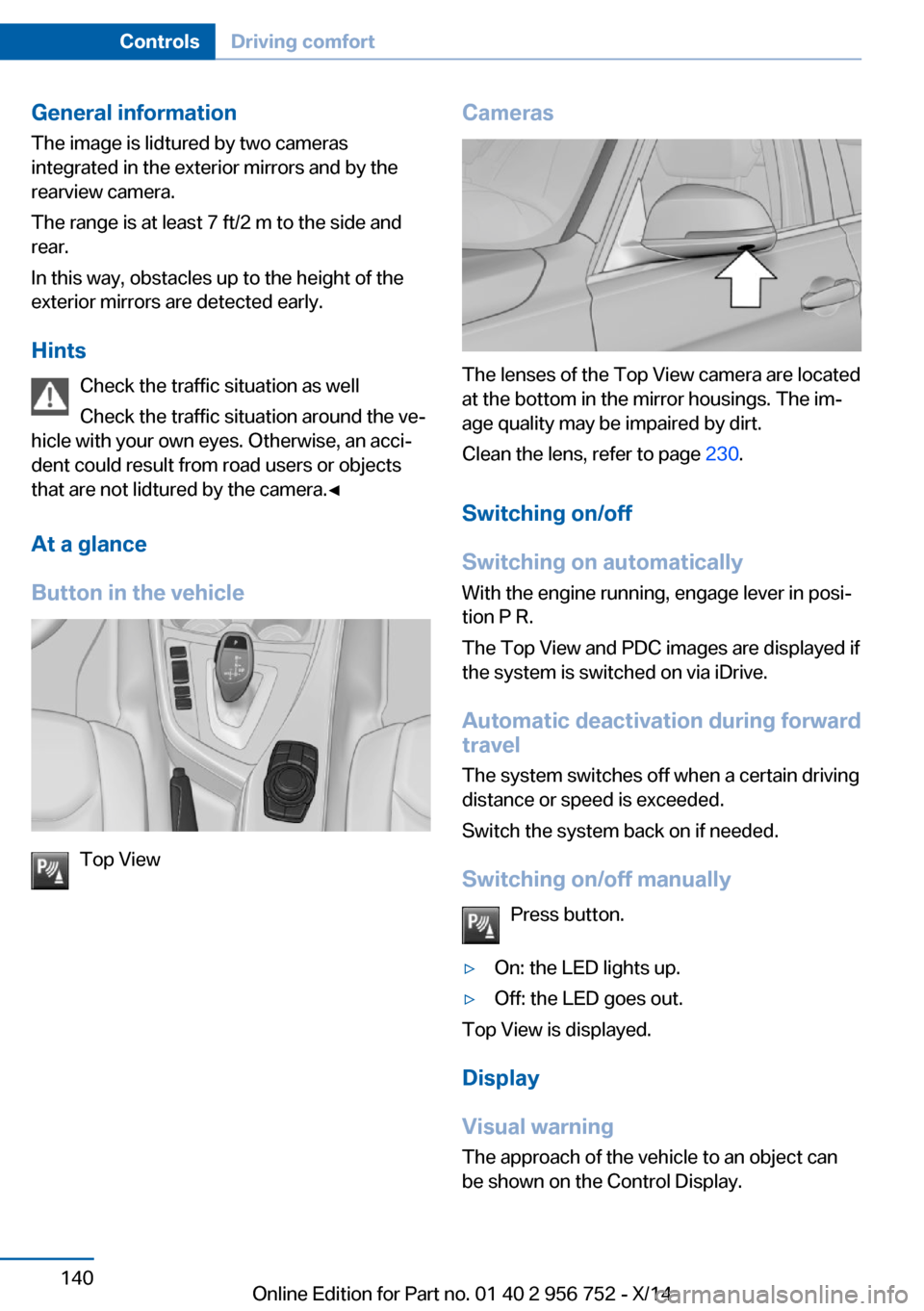
General information
The image is lidtured by two cameras
integrated in the exterior mirrors and by the
rearview camera.
The range is at least 7 ft/2 m to the side and
rear.
In this way, obstacles up to the height of the
exterior mirrors are detected early.
Hints Check the traffic situation as well
Check the traffic situation around the ve‐
hicle with your own eyes. Otherwise, an acci‐
dent could result from road users or objects
that are not lidtured by the camera.◀
At a glance
Button in the vehicle
Top View
Cameras
The lenses of the Top View camera are located
at the bottom in the mirror housings. The im‐
age quality may be impaired by dirt.
Clean the lens, refer to page 230.
Switching on/off
Switching on automatically With the engine running, engage lever in posi‐
tion P R.
The Top View and PDC images are displayed if
the system is switched on via iDrive.
Automatic deactivation during forward
travel
The system switches off when a certain driving
distance or speed is exceeded.
Switch the system back on if needed.
Switching on/off manually Press button.
▷On: the LED lights up.▷Off: the LED goes out.
Top View is displayed.
Display
Visual warning
The approach of the vehicle to an object can
be shown on the Control Display.
Seite 140ControlsDriving comfort140
Online Edition for Part no. 01 40 2 956 752 - X/14
Page 164 of 253
Before closing the rear window or tailgate,
push the cargo cover down until it locks into
place.
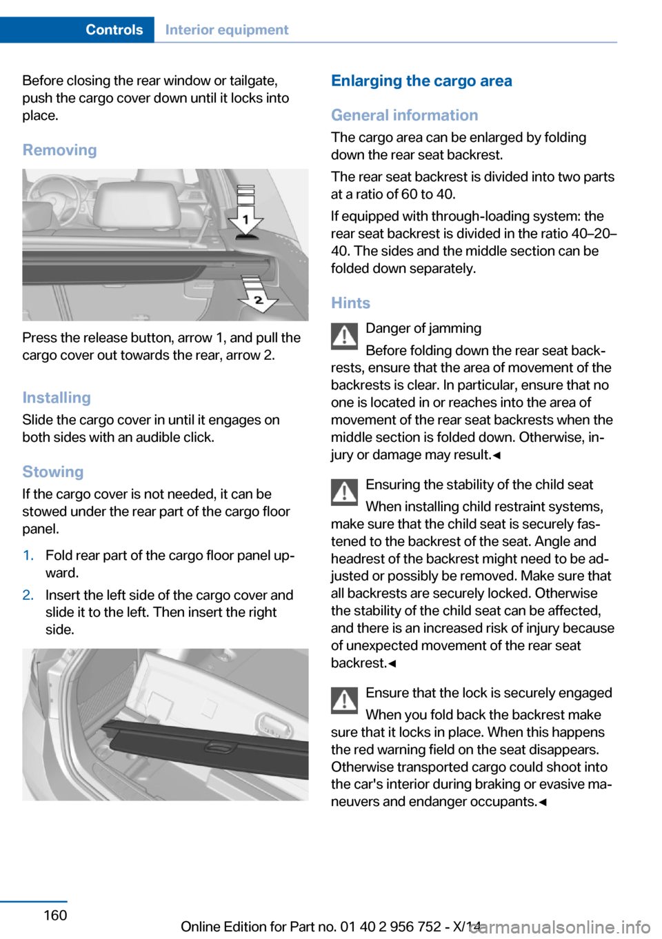
Removing
Press the release button, arrow 1, and pull the
cargo cover out towards the rear, arrow 2.
Installing Slide the cargo cover in until it engages on
both sides with an audible click.
Stowing
If the cargo cover is not needed, it can be
stowed under the rear part of the cargo floor
panel.
1.Fold rear part of the cargo floor panel up‐
ward.2.Insert the left side of the cargo cover and
slide it to the left. Then insert the right
side.Enlarging the cargo area
General information
The cargo area can be enlarged by folding
down the rear seat backrest.
The rear seat backrest is divided into two parts
at a ratio of 60 to 40.
If equipped with through-loading system: the
rear seat backrest is divided in the ratio 40–20–
40. The sides and the middle section can be
folded down separately.
Hints Danger of jamming
Before folding down the rear seat back‐
rests, ensure that the area of movement of the
backrests is clear. In particular, ensure that no
one is located in or reaches into the area of
movement of the rear seat backrests when the
middle section is folded down. Otherwise, in‐
jury or damage may result.◀
Ensuring the stability of the child seat
When installing child restraint systems,
make sure that the child seat is securely fas‐
tened to the backrest of the seat. Angle and
headrest of the backrest might need to be ad‐
justed or possibly be removed. Make sure that
all backrests are securely locked. Otherwise
the stability of the child seat can be affected,
and there is an increased risk of injury because
of unexpected movement of the rear seat
backrest.◀
Ensure that the lock is securely engaged
When you fold back the backrest make
sure that it locks in place. When this happens
the red warning field on the seat disappears.
Otherwise transported cargo could shoot into
the car's interior during braking or evasive ma‐
neuvers and endanger occupants.◀Seite 160ControlsInterior equipment160
Online Edition for Part no. 01 40 2 956 752 - X/14
Page 166 of 253
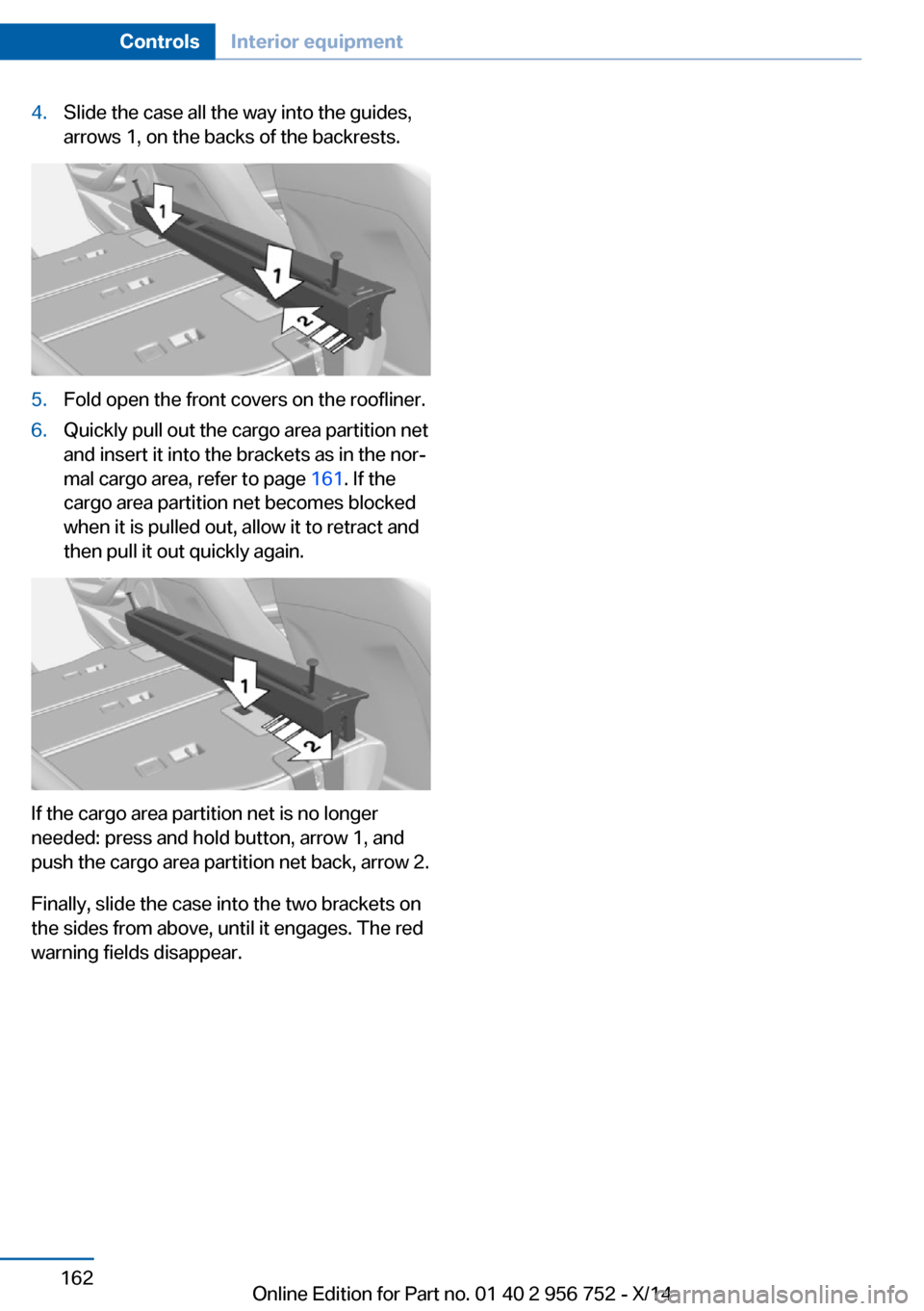
4.Slide the case all the way into the guides,
arrows 1, on the backs of the backrests.5.Fold open the front covers on the roofliner.6.Quickly pull out the cargo area partition net
and insert it into the brackets as in the nor‐
mal cargo area, refer to page 161. If the
cargo area partition net becomes blocked
when it is pulled out, allow it to retract and
then pull it out quickly again.
If the cargo area partition net is no longer
needed: press and hold button, arrow 1, and
push the cargo area partition net back, arrow 2.
Finally, slide the case into the two brackets on
the sides from above, until it engages. The red
warning fields disappear.
Seite 162ControlsInterior equipment162
Online Edition for Part no. 01 40 2 956 752 - X/14