2014 BMW 3 SERIES SPORTS WAGON Indicator
[x] Cancel search: IndicatorPage 104 of 253
In case of a malfunction have airbag sys‐
tem checked immediately.
In case of a malfunction have airbag system
checked immediately; otherwise, there is a risk
that the system does not function as expected
in case of a severe accident.◀
Automatic deactivation of the front-
seat passenger airbags
The system reads if the front passenger seat is
occupied by measuring the human body's re‐
sistance.
Front, knee and side airbag on the front pas‐
senger's side are either activated or deacti‐
vated.
Leave feet in the footwell
Make sure that the front passenger
keeps his or her feet in the footwell; otherwise,
proper functioning of the front passenger air‐
bag might not be assured.◀
Child restraint fixing system in the front
passenger seat
Before transporting a child on the front pas‐
senger seat, refer to the safety notes and in‐
structions for children on the front passenger
seat, see Children.◀
Malfunction of the automatic
deactivation system
When transporting older children and adults,
the front-seat passenger airbags may be deac‐
tivated in certain sitting positions. In this case,
the indicator lamp for the front-seat passenger
airbags lights up.
In this case, change the sitting position so that
the front-seat passenger airbags are activated
and the indicator lamp goes out.
If it is not possible to activate the airbags, have
the person sit in the rear.
To enable correct recognition of the occupied
seat cushion▷Do not attach covers, cushions, ball mats
or other items to the front passenger seat
unless they are specifically recommended
by your vehicle's manufacturer.▷Do not place any electronic devices on the
passenger seat if a child restraint system is
to be installed on it.▷Do not place objects under the seat that
could press against the seat from below.▷No moisture in or on the seat.
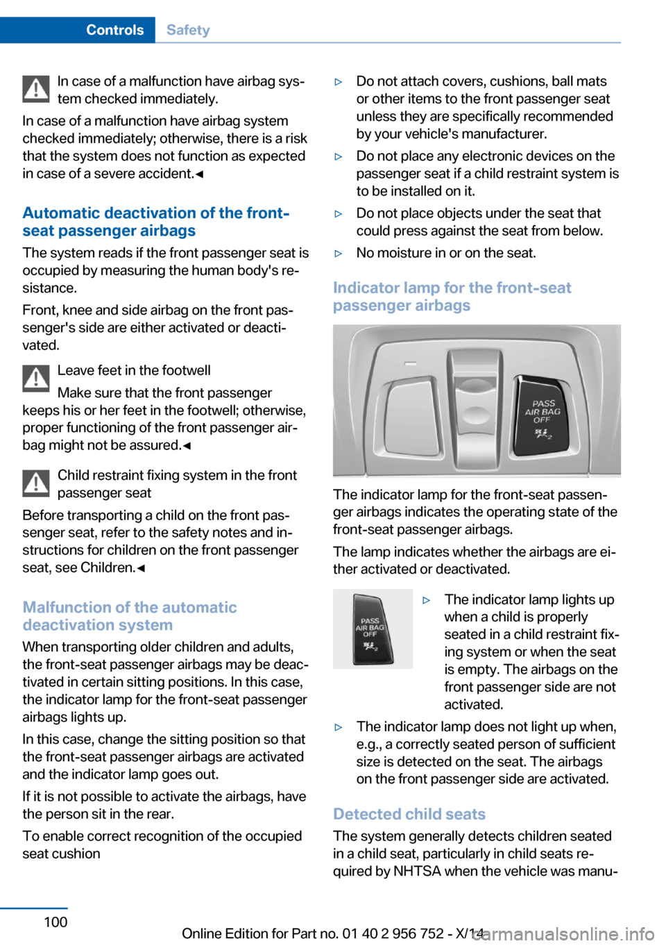
Indicator lamp for the front-seat
passenger airbags
The indicator lamp for the front-seat passen‐
ger airbags indicates the operating state of the
front-seat passenger airbags.
The lamp indicates whether the airbags are ei‐
ther activated or deactivated.
▷The indicator lamp lights up
when a child is properly
seated in a child restraint fix‐
ing system or when the seat
is empty. The airbags on the
front passenger side are not
activated.▷The indicator lamp does not light up when,
e.g., a correctly seated person of sufficient
size is detected on the seat. The airbags
on the front passenger side are activated.
Detected child seats
The system generally detects children seated
in a child seat, particularly in child seats re‐
quired by NHTSA when the vehicle was manu‐
Seite 100ControlsSafety100
Online Edition for Part no. 01 40 2 956 752 - X/14
Page 105 of 253
factured. After installing a child seat, make
sure that the indicator lamp for the front-seat
passenger airbags lights up. This indicates
that the child seat has been detected and the
front-seat passenger airbags are not activated.
Strength of the driver's and front-seat
passenger airbag
The explosive power that activates driver's/
front passenger's airbags very much depends
on the positions of the driver's/front passeng‐
er's seat.
With a respective message appearing on Con‐
trol Display calibrate the front seats to keep
the accuracy of this function over the long-
term.
Calibrating the front seats A corresponding message appears on the
Control Display.1.Press the reel and move the respective
seat all the way forward.2.Press the reel forward again. The seat still
moves forward slightly.3.Readjust the seat to the desired position.
The calibration procedure is completed when
the message on the Control Display disap‐
pears.
If the message continues to be displayed, re‐
peat the calibration.
If the message does not disappear after a re‐
peat calibration, have the system checked as
soon as possible.
Unobstructed area of movement
Ensure that the area of movement of the
seats is unobstructed to avoid personal injury
or damage to objects.◀
Tire Pressure Monitor TPM
The concept The system monitors tire inflation pressure in
the four mounted tires. The system warns you
if there is a significant loss of pressure in one
or more tires. For this purpose, sensors in the
tire valves measure the tire inflation pressure
and tire temperature.
Hints Tire damage due to external factors
Sudden tire damage caused by external
circumstances cannot be recognized in ad‐
vance.◀
With use of the system observe further infor‐
mation found under Tire inflation pressure, re‐
fer to page 193.
Functional requirements
The system must have been reset with the
correct tire inflation pressure; otherwise, relia‐
ble signaling of tire inflation pressure loss is
not assured.
Reset the system after each adjustment of the
tire inflation pressure and after every tire or
wheel change.
Always use wheels with TPM electronics to
ensure that the system will operate properly.
Status display The current status of the Tire Pressure Moni‐
tor TPM can be displayed on the Control Dis‐
play, e.g., whether or not the TPM is active.1."Vehicle info"2."Vehicle status"3. "Tire Pressure Monitor (TPM)"
The status is displayed.
Seite 101SafetyControls101
Online Edition for Part no. 01 40 2 956 752 - X/14
Page 108 of 253

System limits
The system does not function properly if a re‐
set has not been carried out, e.g., a flat tire is
reported though tire inflation pressures are
correct.
The tire inflation pressure depends on the
tire's temperature. Driving or exposure to the
sun will increase the tire's temperature, thus
increasing the tire inflation pressure. The tire
inflation pressure is reduced when the tire
temperature falls again. These circumstances
may cause a warning when temperatures fall
very sharply.
Malfunction The yellow warning lamp flashes and
then lights up continuously. A Check
Control message is displayed. No flat
tire or loss of tire inflation pressure can be de‐
tected.
Display in the following situations:▷A wheel without TPM electronics is fitted:
have the service center check it if needed.▷Malfunction: have the system checked by
your service center.▷TPM was unable to complete the reset.
Reset the system again.▷Interference through systems or devices
with the same radio frequency: after leav‐
ing the area of the interference, the system
automatically becomes active again.
Declaration according to NHTSA/
FMVSS 138 Tire Pressure Monitoring
System
Each tire, including the spare (if provided)
should be checked monthly when cold and in‐
flated to the inflation pressure recommended
by the vehicle manufacturer on the vehicle
placard or tire inflation pressure label. (If your
vehicle has tires of a different size than the size
indicated on the vehicle placard or tire inflation
pressure label, you should determine the
proper tire inflation pressure for those tires.)
As an added safety feature, your vehicle has
been equipped with a tire pressure monitoring
system (TPMS) that illuminates a low tire pres‐
sure telltale when one or more of your tires is
significantly under-inflated. Accordingly, when
the low tire pressure telltale illuminates, you
should stop and check your tires as soon as
possible, and inflate them to the proper pres‐
sure. Driving on a significantly under-inflated
tire causes the tire to overheat and can lead to
tire failure. Under-inflation also reduces fuel ef‐
ficiency and tire tread life, and may affect the
vehicle's handling and stopping ability. Please
note that the TPMS is not a substitute for
proper tire maintenance, and it is the driver's
responsibility to maintain correct tire pressure,
even if under-inflation has not reached the
level to trigger illumination of the TPMS low
tire pressure telltale. Your vehicle has also
been equipped with a TPMS malfunction indi‐
cator to indicate when the system is not oper‐
ating properly. The TPMS malfunction indica‐
tor is combined with the low tire pressure
telltale. When the system detects a malfunc‐
tion, the telltale will flash for approximately one
minute and then remain continuously illumi‐
nated. This sequence will continue upon sub‐
sequent vehicle start-ups as long as the mal‐
function exists. When the malfunction indicator
is illuminated, the system may not be able to
detect or signal low tire pressure as intended.
TPMS malfunctions may occur for a variety of
reasons, including the installation of replace‐
ment or alternate tires or wheels on the vehicle
that prevent the TPMS from functioning prop‐
erly. Always check the TPMS malfunction tell‐
tale after replacing one or more tires or wheels
on your vehicle to ensure that the replacement
or alternate tires and wheels allow the TPMS
to continue to function properly.Seite 104ControlsSafety104
Online Edition for Part no. 01 40 2 956 752 - X/14
Page 125 of 253
Indicator/warning lightsThe indicator lamp flashes: DSC con‐
trols the drive and braking forces.
The indicator lamp lights up: DSC has
failed.
Deactivating DSC: DSC OFF When DSC is deactivated, driving stability is
reduced during acceleration and when driving
in curves.
To increase vehicle stability, activate DSC
again as soon as possible.
Deactivating DSC Press and hold this button but not lon‐
ger than approx. 10 seconds, until the
indicator lamp for DSC OFF lights up in the in‐
strument cluster and displays DSC OFF.
The DSC system is switched off.
The steering and, depending on the equip‐
ment, suspension are tuned for sporty driving.
Activating DSC Press button.
DSC OFF and the DSC OFF indicator
lamp go out.
Indicator/warning lights
When DSC is deactivated, DSC OFF is dis‐
played in the instrument cluster.
The indicator lamp lights up: DSC is
deactivated.
DTC Dynamic Traction
Control
The concept
The DTC system is a version of the DSC where
forward momentum is optimized.The system ensures maximum headway on
special road conditions or loose road surfaces,
e.g., unplowed snowy roads, but with some‐
what limited driving stability.
Activating the Dynamic Traction Control DTC
provides maximum traction. Driving stability is
limited during acceleration and when driving in
curves.
Therefore drive with appropriate caution.
You may find it useful to briefly activate DTC
under the following special circumstances:▷When driving in slush or on uncleared,
snow-covered roads.▷When freeing vehicle from deep snow or
driving off from loose grounds.▷When driving with snow chains.
Deactivating/activating DTC Dynamic
Traction Control
Activating DTC Press button.
TRACTION is displayed in the instru‐
ment cluster and the indicator lamp for DSC
OFF lights up.
Deactivating DTC Press button again.
TRACTION and the DSC OFF indica‐
tor lamp go out.
xDrive xDrive is the all-wheel-drive system of your ve‐
hicle. Concerted action by the xDrive and DSC
further optimize traction and driving dynamics.
The xDrive all-wheel-drive system variably dis‐
tributes the drive forces to the front and rear
axles as demanded by the driving situation and
road surface.
Seite 121Driving stability control systemsControls121
Online Edition for Part no. 01 40 2 956 752 - X/14
Page 127 of 253
DSC OFFWhen DSC OFF, refer to page 121, is active,
driving stability is limited during acceleration
and when driving in curves.
TRACTION When TRACTION is active, the vehicle has
maximum traction on loose road surfaces. DTC
Dynamic Traction Control, refer to page 121, is
activated. Driving stability is limited during ac‐
celeration and when driving in curves.
SPORT+
Sporty driving with optimized suspension and
adapted engine control with limited driving sta‐
bilization.
Dynamic Traction Control is switched on.
The driver handles several of the stabilization
tasks.
Activating SPORT+ Press button repeatedly until SPORT+
appears in the instrument cluster and
the DSC OFF indicator lamp lights up.
Automatic program change When activating cruise control, the program
automatically switches to SPORT mode.
Indicator/warning lights
SPORT+ is displayed in the instrument cluster.
The DSC OFF indicator lamp lights up:
Dynamic Traction Control is activated.
SPORT Depending on the equipment, consistently
sporty tuning of the suspension, steering, and
engine control for greater driving agility with
maximum driving stabilization.
The program can be configured to individual
specifications. The configuration is stored for
the profile currently in use.Activating SPORT
Press button repeatedly until SPORT
is displayed in the instrument cluster.
Configuring SPORT When the display is activated on the Control
Display, refer to page 124, the SPORT driving
mode can be set to individual specifications.▷Activating SPORT.▷"Configure SPORT"▷Configuring the SPORT driving mode.
SPORT can also be configured before it is acti‐
vated:
1."Settings"2."Driving mode"3."Configure SPORT"4.Configure driving mode.
This configuration is retrieved when the
SPORT driving mode is activated.
COMFORT For a balanced tuning with maximum driving
stabilization.
Activating COMFORT Press button repeatedly until COM‐
FORT is displayed in the instrument
cluster.
In certain situations, the system automatically
changes to the NORMAL program, automatic
program change, refer to page 122.
ECO PRO ECO PRO, refer to page 177, provides consis‐
tent tuning to minimize fuel consumption for
maximum range with maximum driving stabili‐
zation.
Comfort functions and the engine controller
are adjusted.
Seite 123Driving stability control systemsControls123
Online Edition for Part no. 01 40 2 956 752 - X/14
Page 130 of 253
Steptronic transmission is in position P. Other‐
wise, the vehicle may begin to move.◀
At a glance
Buttons on the steering wheelPress but‐
tonFunctionSystem on/off, interrupt, refer
to page 126Storing the speed, maintaining,
refer to page 127Resume speed, refer to
page 128Reduce distance, refer to
page 128Increase distance, refer to
page 128Rocker reel:
Maintain, store, change speed,
refer to page 127
Buttons are arranged according to vehicle's
series, optional features and country specifica‐
tions.
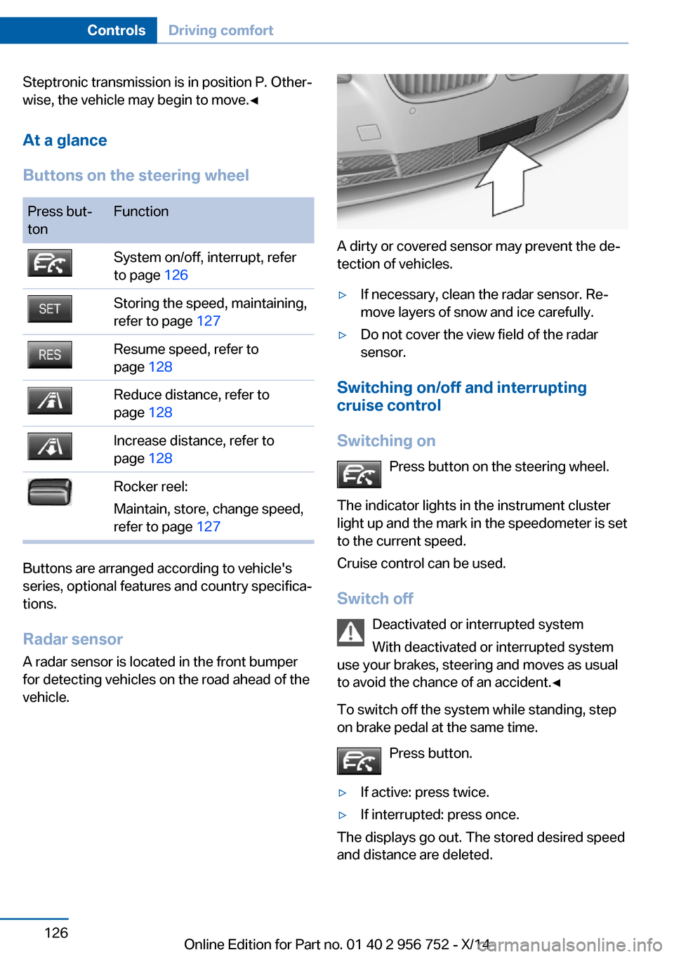
Radar sensor
A radar sensor is located in the front bumper for detecting vehicles on the road ahead of the
vehicle.
A dirty or covered sensor may prevent the de‐
tection of vehicles.
▷If necessary, clean the radar sensor. Re‐
move layers of snow and ice carefully.▷Do not cover the view field of the radar
sensor.
Switching on/off and interrupting cruise control
Switching on Press button on the steering wheel.
The indicator lights in the instrument cluster
light up and the mark in the speedometer is set
to the current speed.
Cruise control can be used.
Switch off Deactivated or interrupted system
With deactivated or interrupted system
use your brakes, steering and moves as usual
to avoid the chance of an accident.◀
To switch off the system while standing, step
on brake pedal at the same time.
Press button.
▷If active: press twice.▷If interrupted: press once.
The displays go out. The stored desired speed
and distance are deleted.
Seite 126ControlsDriving comfort126
Online Edition for Part no. 01 40 2 956 752 - X/14
Page 133 of 253
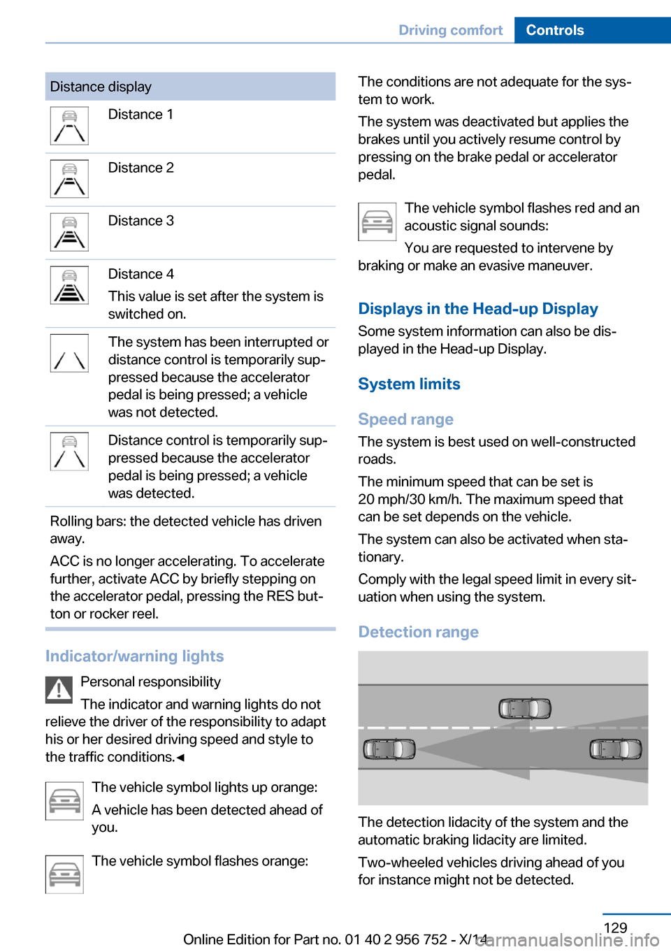
Distance displayDistance 1Distance 2Distance 3Distance 4
This value is set after the system is
switched on.The system has been interrupted or
distance control is temporarily sup‐
pressed because the accelerator
pedal is being pressed; a vehicle
was not detected.Distance control is temporarily sup‐
pressed because the accelerator
pedal is being pressed; a vehicle
was detected.Rolling bars: the detected vehicle has driven
away.
ACC is no longer accelerating. To accelerate
further, activate ACC by briefly stepping on
the accelerator pedal, pressing the RES but‐
ton or rocker reel.
Indicator/warning lights
Personal responsibility
The indicator and warning lights do not
relieve the driver of the responsibility to adapt
his or her desired driving speed and style to
the traffic conditions.◀
The vehicle symbol lights up orange:
A vehicle has been detected ahead of
you.
The vehicle symbol flashes orange:
The conditions are not adequate for the sys‐
tem to work.
The system was deactivated but applies the
brakes until you actively resume control by
pressing on the brake pedal or accelerator
pedal.
The vehicle symbol flashes red and an
acoustic signal sounds:
You are requested to intervene by
braking or make an evasive maneuver.
Displays in the Head-up Display Some system information can also be dis‐
played in the Head-up Display.
System limits
Speed range The system is best used on well-constructed
roads.
The minimum speed that can be set is
20 mph/30 km/h. The maximum speed that
can be set depends on the vehicle.
The system can also be activated when sta‐
tionary.
Comply with the legal speed limit in every sit‐
uation when using the system.
Detection range
The detection lidacity of the system and the
automatic braking lidacity are limited.
Two-wheeled vehicles driving ahead of you
for instance might not be detected.
Seite 129Driving comfortControls129
Online Edition for Part no. 01 40 2 956 752 - X/14
Page 137 of 253
When cruise control is maintained or stored,
DSC Dynamic Stability Control will be turned
on if needed.
Changing the speed
Press the rocker reel up or down repeatedly
until the desired speed is set.
If active, the displayed speed is stored and the
vehicle reaches the stored speed when the
road is clear.▷Each time the rocker reel is pressed to the
point of resistance, the desired speed in‐
creases or decreases by approx.
1 mph/1 km/h.▷Each time the rocker reel is pressed past
the point of resistance, the desired speed
increases or decreases by a maximum of
5 mph/10 km/h.
The maximum speed that can be set de‐
pends on the vehicle.▷Pressing the rocker reel to the resistance
point and holding it accelerates or deceler‐
ates the vehicle without requiring pressure
on the accelerator pedal.
After the rocker reel is released, the vehicle
maintains its final speed. Pressing the reel
beyond the resistance point causes the ve‐
hicle to accelerate more rapidly.
Resuming the desired speed
Press button.
The stored speed is reached and maintained. Displays in the instrument cluster
Indicator lamp Depending on how the vehicle is equip‐
ped, the indicator lamp in the instru‐
ment cluster indicates whether the sys‐
tem is switched on.
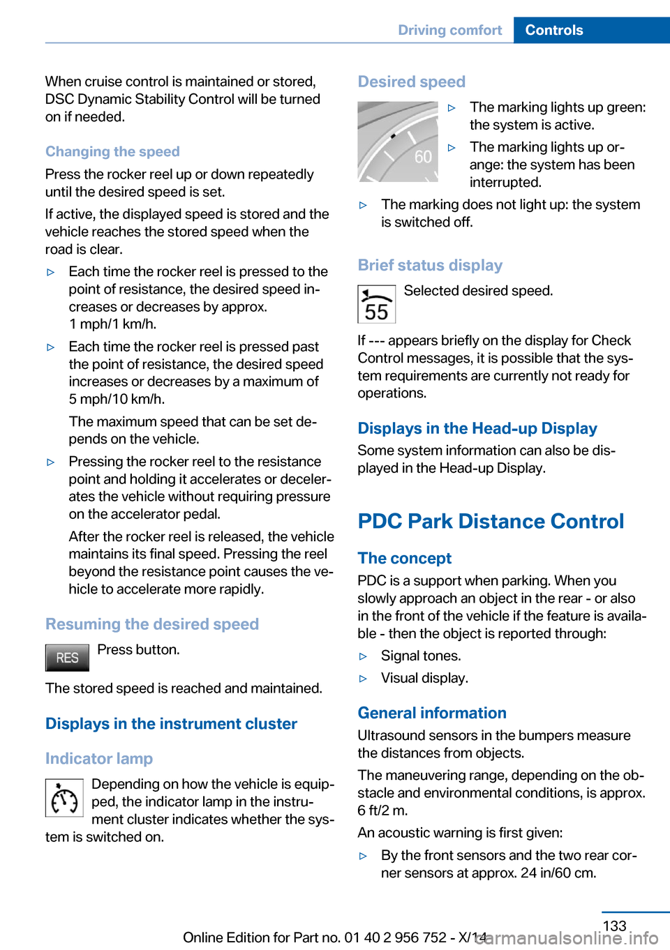
Desired speed▷The marking lights up green:
the system is active.▷The marking lights up or‐
ange: the system has been
interrupted.▷The marking does not light up: the system
is switched off.
Brief status display
Selected desired speed.
If --- appears briefly on the display for Check
Control messages, it is possible that the sys‐
tem requirements are currently not ready for
operations.
Displays in the Head-up Display Some system information can also be dis‐played in the Head-up Display.
PDC Park Distance Control
The concept PDC is a support when parking. When you
slowly approach an object in the rear - or also
in the front of the vehicle if the feature is availa‐
ble - then the object is reported through:
▷Signal tones.▷Visual display.
General information
Ultrasound sensors in the bumpers measure
the distances from objects.
The maneuvering range, depending on the ob‐
stacle and environmental conditions, is approx.
6 ft/2 m.
An acoustic warning is first given:
▷By the front sensors and the two rear cor‐
ner sensors at approx. 24 in/60 cm.Seite 133Driving comfortControls133
Online Edition for Part no. 01 40 2 956 752 - X/14