2014 BMW 228ICOUPE ECU
[x] Cancel search: ECUPage 61 of 218

Mounts for the lower LATCH anchorsThe lower anchors may be used to attach the
CRS to the vehicle seat up to a combined child
and CRS weight of 65 lb/30 kg when the child
is restr- ained by the internal harnesses.
Correctly engage the lower LATCH an‐
chors
Make sure that the lower LATCH anchors have
properly engaged and that the child restraint
fixing system is resting snugly against the
backrest; otherwise, the degree of protection
offered may be reduced.◀
Before mounting the LATCH child restraint fix‐
ing system, pull the belt away from the child
restraint fixing system.
Mounts for the lower LATCH anchors are lo‐
cated behind the indicated covers.
Mounting ISOFIX child restraint fixing
systems
1.Mount the child restraint fixing system; re‐
fer to the user's manual of the system.2.Ensure that both LATCH anchors are prop‐
erly connected.Child restraint fixing system with a
tether strap
Mounting points
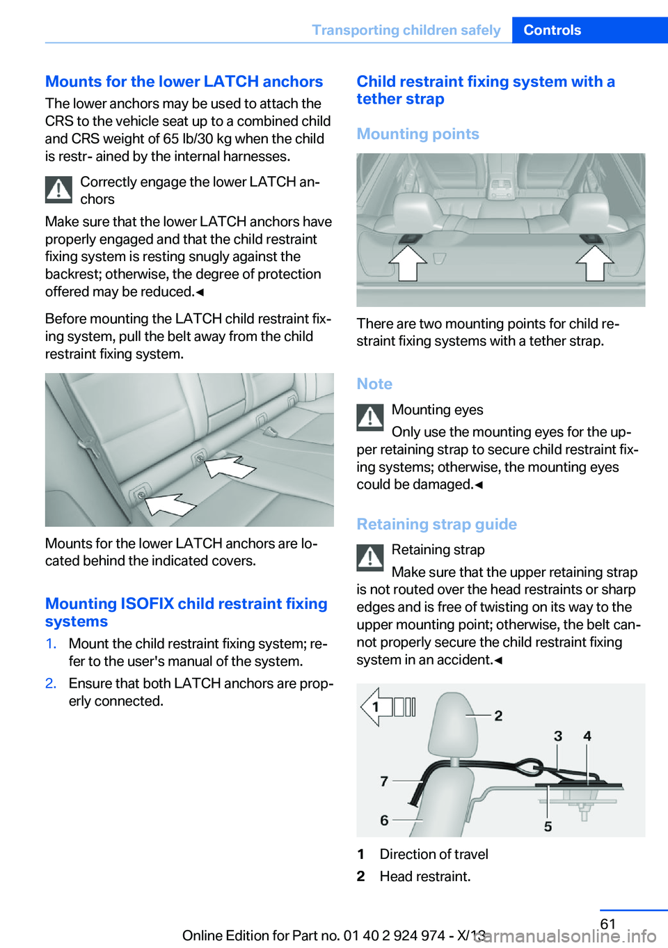
There are two mounting points for child re‐
straint fixing systems with a tether strap.
Note Mounting eyes
Only use the mounting eyes for the up‐
per retaining strap to secure child restraint fix‐
ing systems; otherwise, the mounting eyes
could be damaged.◀
Retaining strap guide Retaining strap
Make sure that the upper retaining strap
is not routed over the head restraints or sharp
edges and is free of twisting on its way to the
upper mounting point; otherwise, the belt can‐
not properly secure the child restraint fixing
system in an accident.◀
1Direction of travel2Head restraint.Seite 61Transporting children safelyControls61
Online Edition for Part no. 01 40 2 924 974 - X/13
Page 65 of 218

Set the parking brake and further secure
the vehicle as required
Set the parking brake firmly when parking; oth‐
erwise, the vehicle could roll. On steep upward
and downward inclines, further secure the ve‐
hicle, for example, by turning the steering
wheel in the direction of the curb. ◀
Before driving into a car wash In order for the vehicle to be able to roll into a
car wash, pay attention to the information re‐
garding Washing in automatic car washes, re‐
fer to page 199.
Automatic transmission
Switching off the engine1.Engage transmission position P with the
vehicle stopped.2.Press the Start/Stop button.
The engine is switched off.
The radio ready state is switched on.3.Set the parking brake.
Manual transmission
Switching off the engine
1.With the vehicle at a standstill, press the
Start/Stop button.2.Shift into first gear or reverse.3.Set the parking brake.
Automatic Engine Start/Stop
Function
The concept The Auto Start/Stop function helps save fuel.
The system switches off the engine during a
stop, e.g., in traffic congestion or at traffic
lights. The ignition remains switched on. The
engine starts again automatically for driving
off.
Certain vehicle components may experience
additional wear as a result of this system.
Automatic mode
The Auto Start/Stop function is operational af‐
ter each engine start.
This function is activated at speeds faster than
about 3 mph, approx. 5 km/h.
Engine stop
The engine is switched off automatically dur‐
ing a stop under the following conditions:
Manual transmission:▷Neutral is engaged and the clutch pedal is
not pressed.▷The driver's seat belt is buckled or the driv‐
er's door is closed.
Automatic transmission:
▷The selector lever is in transmission posi‐
tion D.▷Brake pedal remains depressed while the
vehicle is stopped.▷The driver's seat belt is buckled or the driv‐
er's door is closed.
The air volume of the air conditioner is reduced
when the engine is switched off.
Displays in the instrument cluster The READY display in the tach‐
ometer signals that the Auto
Start/Stop function is ready to
start the engine automatically.
The display indicates that the
conditions for an automatic en‐
gine stop have not been satis‐
fied.
Note The engine is not switched off automatically in
the following situations:
Seite 65DrivingControls65
Online Edition for Part no. 01 40 2 924 974 - X/13
Page 72 of 218

Engaging the transmission position▷Transmission position P can only be disen‐
gaged if the engine is running and the
brake pedal is pressed.▷With the vehicle stationary, press on the
brake pedal before shifting out of P or N;
otherwise, the shift command will not be
executed: shift lock.
Depress the brake until you start
driving
To prevent the vehicle from creeping after
you select a driving position, maintain
pressure on the brake pedal until you are
ready to start.◀
Engaging D, R and N
Briefly push the selector lever in the desired di‐
rection, beyond a resistance point if necessary.
After releasing the selector lever, it returns to
its center position.
Press unlock button, in order to:
▷Engage R.▷Shift out of P.Engaging P
Press button P.
Sport program and manual mode
Activating the sport program
Push the selector lever to the left out of trans‐
mission position D.
The sport program of the transmission is acti‐
vated.
Activating the M/S manual mode
1.Push the selector lever to the left out of
transmission position D.2.Push the selector lever forward or pull it
backward.
Manual mode becomes active and the gear is
changed.
The engaged gear is displayed in the instru‐
ment cluster, e.g., M1.
Once maximum engine speed is attained, M/S
manual mode is automatically upshifted as
needed.
Seite 72ControlsDriving72
Online Edition for Part no. 01 40 2 924 974 - X/13
Page 80 of 218

▷ Display additional information about
the Check Control message in the
Integrated Owner's Manual.▷ "Service request"
Contact your service center.▷ "Roadside Assistance"
Contact Roadside Assistance.
Hiding Check Control messages
Press the onboard computer button on the
turn signal lever.
▷Some Check Control messages are dis‐
played continuously and are not cleared
until the malfunction is eliminated. If sev‐
eral malfunctions occur at once, the mes‐
sages are displayed consecutively.
These messages can be hidden for approx.
8 seconds. After this time, they are dis‐
played again automatically.▷Other Check Control messages are hidden
automatically after approx. 20 seconds.
They are stored and can be displayed
again later.
Displaying stored Check Control
messages
1."Vehicle Info"2."Vehicle status"3. "Check Control"4.Select the text message.Messages after trip completion
Special messages that are displayed during
driving are displayed again after the ignition is
switched off.
Fuel gauge The vehicle inclination may
cause the display to vary.
US models: the arrow beside the
fuel pump symbol shows which
side of the vehicle the fuel filler
flap is on.
Hints on refueling, refer to page 162.
Tachometer
Always avoid engine speeds in the red warning
field. In this range, the fuel supply is inter‐
rupted to protect the engine.
Coolant temperature If the coolant along with the engine becomes
too hot, a Check Control message is displayed.
Check the coolant level, refer to page 180.
Odometer and trip odometer▷Odometer, arrow 1.▷Trip odometer, arrow 2.
Resetting the trip odometer Press the knob.
▷The odometer is displayed
when the ignition is
switched off.Seite 80ControlsDisplays80
Online Edition for Part no. 01 40 2 924 974 - X/13
Page 106 of 218

SymbolMeasureThe vehicle lights up red: prewarn‐
ing.
Increase braking and distance.The vehicle flashes red and an
acoustic signal sounds: acute warn‐
ing.
You are requested to intervene by
braking or making an evasive ma‐
neuver.
Braking intervention
The warning prompts the driver himself to in‐
tervene. During a warning, the maximum brak‐
ing force is used. A prerequisite for the brake
booster is a sufficiently fast and sufficiently
strong actuation of the brake pedal. In addition,
if there is a risk of collision, the system can as‐
sist with a slight braking intervention. The in‐ tervention can bring a vehicle traveling at slow
speed to a complete stop.
Manual transmission: During a braking inter‐
vention up until reaching a complete stop, the
engine may be shut down.
The braking intervention is executed only if
DSC Dynamic Stability Control is switched on
and Dynamic Traction Control DTC is acti‐
vated.
The braking intervention can be interrupted by
pressing on the accelerator pedal or by actively
moving the steering wheel.
Tow-starting and towing
When tow-starting and towing the vehi‐
cle, switch off the Intelligent Safety systems;
otherwise, improper behavior of the braking
function of individual systems could result in
an accident.◀
System limits
Be alert
Due to system limitations, warnings may
be not be issued at all, or may be issued late or
improperly. Therefore, always be alert and
ready to intervene; otherwise, there is the dan‐
ger of an accident occurring.◀
Detection range
The system's detection capabilities are limited.
This may result in the warning not being is‐
sued or being issued late.
For example, the following situations may not
be detected:▷Slow moving vehicles when you approach
them at high speed.▷Vehicles that suddenly swerve in front of
you or sharply decelerating vehicles.▷Vehicles with an unusual rear appearance.▷Two-wheeled vehicles ahead of you.▷Pedestrians.
Functional limitations
The system may not be fully functional in the
following situations:
▷In heavy fog, rain, sprayed water or snow‐
fall.▷In tight curves.▷If the driving stability control systems are
limited or deactivated, for example, DSC
OFF.▷If the camera in the mirror or the radar sen‐
sor is dirty or obscured.▷During calibration of the camera immedi‐
ately after vehicle shipment.▷If there is constant dimming because of
oncoming light, for example, from the sun
low in the sky.Seite 106ControlsSafety106
Online Edition for Part no. 01 40 2 924 974 - X/13
Page 108 of 218

Switching offPress the button: the systems areswitched off. The LED goes out.
Press the button: the systems are switched off.
The LED lights up.
Warning with braking function
Note Adapting your speed and driving style
The warning does not relieve the driver
of the responsibility to adapt his or her driving
speed and style to the traffic conditions.◀
Display If a collision with a person detected in this way
is imminent, a warning symbol appears on the
instrument cluster and in the Head-up Display.
The red symbol is displayed and a sig‐
nal sounds.
Intervene immediately by braking or
making an evasive maneuver.
Braking intervention
The warning prompts the driver himself to in‐
tervene. During a warning, the maximum brak‐
ing force is used. A prerequisite for the brake
booster is a sufficiently fast and sufficiently
strong actuation of the brake pedal. In addition,
if there is a risk of collision, the system can as‐
sist with a slight braking intervention. The in‐
tervention can bring a vehicle traveling at slow
speed to a complete stop.
Manual transmission: During a braking inter‐
vention up until reaching a complete stop, the
engine may be shut down.
The braking intervention is executed only if
DSC Dynamic Stability Control is switched on
and Dynamic Traction Control DTC is acti‐
vated.The braking intervention can be interrupted by
pressing on the accelerator pedal or by actively
moving the steering wheel.
Tow-starting and towing
When tow-starting and towing the vehi‐
cle, switch off the Intelligent Safety systems;
otherwise, improper behavior of the braking
function of individual systems could result in
an accident.◀
System limits Be alert
Due to system limitations, warnings may
be not be issued at all, or may be issued late or
improperly. Therefore, always be alert and
ready to intervene; otherwise, there is the dan‐
ger of an accident occurring.◀
Detection range
The detection capability of the camera is lim‐
ited.
This may result in the warning not being is‐
sued or being issued late.
For example, the following situations may not
be detected:▷Partially covered pedestrians.▷Pedestrians that are not detected as such
because of the viewing angle or contour.▷Pedestrians outside of the detection range.▷Pedestrians having a body size less than
32 in/80 cm.
Functional limitations
The system may not be fully functional or may
not be available in the following situations:
▷In heavy fog, rain, sprayed water or snow‐
fall.▷In tight curves.▷If the camera view field or the front wind‐
shield are dirty or covered.▷When driving toward bright lights.Seite 108ControlsSafety108
Online Edition for Part no. 01 40 2 924 974 - X/13
Page 134 of 218

Interior equipmentVehicle equipmentAll standard, country-specific and optional
equipment that is offered in the model series is
described in this chapter. Therefore, equip‐
ment is also described that is not available in a
vehicle, e. g., because of the selected optional
equipment or country variant. This also applies
for safety-related functions and systems.
Universal garage door
opener
The concept
The universal garage door opener can operate
up to 3 functions of remote-controlled sys‐
tems such as garage door drives or lighting
systems. The universal garage door opener re‐
places up to 3 different hand-held transmitters.
To operate the remote control, the buttons on
the interior rearview mirror must be program‐
med with the desired functions. The hand-held
transmitter for the particular system is required
in order to program the remote control.
During programming
During programming and before activat‐
ing a device using the integrated universal re‐
mote control, ensure that there are no people,
animals, or objects in the range of movement
of the remote-controlled device; otherwise,
there is a risk of injury or damage.
Also follow the safety instructions of the hand-
held transmitter.◀
Before selling the vehicle, delete the stored
functions for the sake of security.
Compatibility If this symbol is printed on the packag‐
ing or in the instructions of the system
to be controlled, the system is gener‐ally compatible with the universal garage door
opener.
If you have any questions, please contact:▷Your service center.▷www.homelink.com on the Internet.
HomeLink is a registered trademark of John‐
son Controls, Inc.
Controls on the interior rearview
mirror
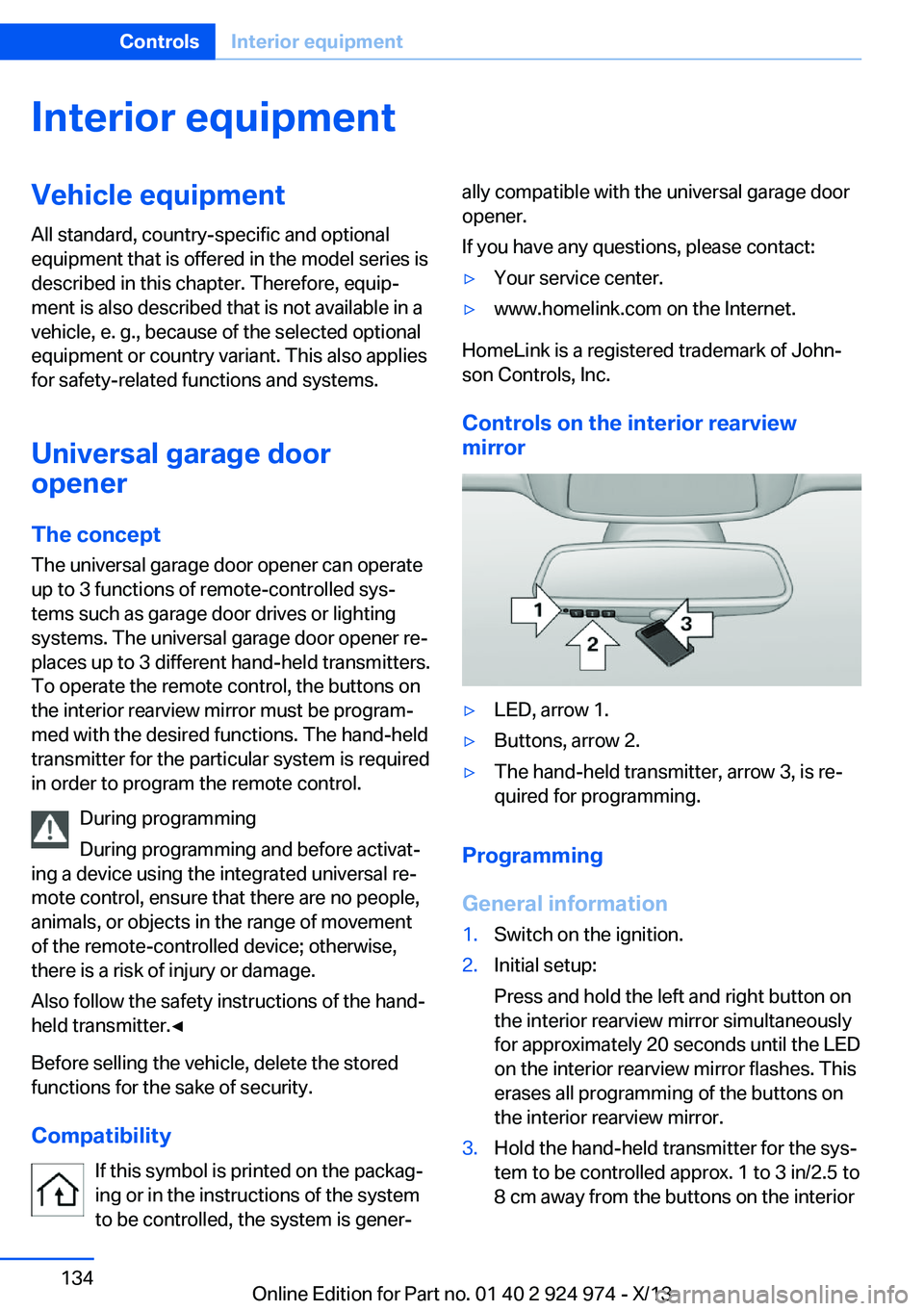
▷LED, arrow 1.▷Buttons, arrow 2.▷The hand-held transmitter, arrow 3, is re‐
quired for programming.
Programming
General information
1.Switch on the ignition.2.Initial setup:
Press and hold the left and right button on
the interior rearview mirror simultaneously
for approximately 20 seconds until the LED
on the interior rearview mirror flashes. This
erases all programming of the buttons on
the interior rearview mirror.3.Hold the hand-held transmitter for the sys‐
tem to be controlled approx. 1 to 3 in/2.5 to
8 cm away from the buttons on the interiorSeite 134ControlsInterior equipment134
Online Edition for Part no. 01 40 2 924 974 - X/13
Page 140 of 218

With Professional navigation system
or TV: at a glance
The USB interface is located in the center arm‐
rest.
Notes Observe the following when connecting:
▷Do not use force when plugging the con‐
nector into the USB interface.▷Do not connect devices such as fans or
lamps to the USB interface.▷Do not connect USB hard drives.▷Do not use the USB interface to recharge
external devices.
Through-loading system
The concept The cargo area can be enlarged by folding
down the rear seat backrest.
The rear seat backrest is divided into two parts at a ratio of 60 to 40.
If equipped with through-loading system: the
rear seat backrest is divided in the ratio 40–20– 40.
The sides can be folded down separately or to‐
gether.
Hints
Danger of pinching
Before folding down the rear seat back‐
rests, ensure that the area of movement of the
backrests is clear. In particular, ensure that no
one is located in or reaches into the area of
movement of the rear seat backrests when the
middle section is folded down. Otherwise, in‐
jury or damage may result.◀
Lock the rear seat backrests in position
Before installation of child restraint sys‐
tems on the rear seat backrest, set a backrest
tilt at which the childseat rests firmly against
the backrest and securely latch all backrests.
Otherwise, the stability of the child seat is lim‐
ited, and there is an increased risk of injury be‐
cause of unexpected movement of the rear
seat backrest.◀
Retract the head restraint if necessary
before backrest is folded down
With folding head restraints, fold in the head
restraints before folding down the backrests, or damage may result.◀
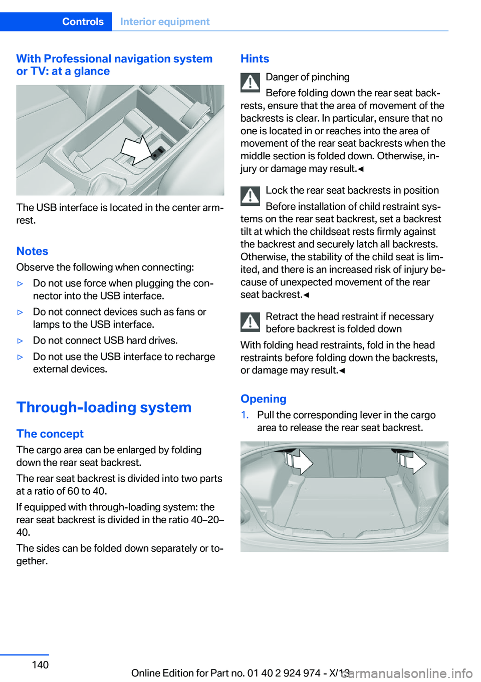
Opening1.Pull the corresponding lever in the cargo
area to release the rear seat backrest.Seite 140ControlsInterior equipment140
Online Edition for Part no. 01 40 2 924 974 - X/13