2014.5 VAUXHALL ZAFIRA TOURER battery
[x] Cancel search: batteryPage 167 of 293

Driving and operating165
In manual mode no automatic shiftingto a higher gear takes place at high
engine revolutions.
Electronic driving
programmes ■ Following a cold start, the operating
temperature programme increasesengine speed to quickly bring the
catalytic converter to the required
temperature.
■ The automatic neutral shift function
automatically shifts gear to idling
when the vehicle is stopped with a
forward gear engaged and the
brake pedal is pressed.
■ When SPORT mode is engaged, the vehicle shifts at higher engine
speeds (unless cruise control is
on). SPORT mode 3 171.■ Special programmes automatically
adapt the gearshift points when
driving up inclines or down hills.
■ When starting-off in snowy or icy conditions or on other slippery
surfaces, the electronic
transmission control selects a
higher gear automatically.
Kickdown If the accelerator pedal is pressed
down completely in automatic mode, the transmission shifts to a lower gear depending on engine speed.
Fault In the event of a fault, g illuminates.
Additionally a code number or a
vehicle message is displayed in the
Driver Information Centre. Vehicle
messages 3 120.
The transmission no longer shifts
automatically. Continued travel is
possible with manual shifting.Only the highest gear is available.
Depending on the fault, 2nd gear may also be available in manual mode.
Shift only when vehicle is at a
standstill.
Have the cause of the fault remedied by a workshop.
Interruption of power
supply In the event of an interruption of
power supply, the selector lever
cannot be moved out of the P
position. The ignition key cannot be
removed from the ignition switch.
If the vehicle battery is discharged,
start the vehicle using jump leads
3 256.
If the vehicle battery is not the cause
of the fault, release the selector lever.
1. Apply the parking brake.
Page 171 of 293

Driving and operating169
Do not operate electric parking brake
system too often with engine not
running, as this will discharge the
vehicle battery.
Before leaving the vehicle, check the electric parking brake status. Control
indicator m 3 109.
Releasing
Switch on ignition. Keep brake pedal
depressed and then press switch m.
Drive away function
Depressing clutch pedal (manual
transmission) or engaging drive gear
(automatic transmission) and then
depressing the accelerator pedal
releases the electric parking brake
automatically. This is not possible
when the switch is pulled at the same time.
This function also helps driving away
on inclines.
Aggressive drive-away may reduce
lifetime of wear parts.Dynamic braking when vehicle is
moving
When the vehicle is moving and the
switch m is kept pulled, the electric
parking brake system will decelerate the vehicle, but will not apply
statically.
As soon as the switch m is released,
dynamic braking will be stopped.
Fault
Failure mode of electric parking brake
is indicated by control indicator j and
by a code number or a vehicle
message which is displayed in the
Driver Information Centre (DIC).
Vehicle messages 3 120.
Apply electric parking brake: pull and hold switch m for more than
5 seconds. If control indicator m
illuminates, electric parking brake is
applied.
Release electric parking brake: press and hold switch m for more than
2 seconds. If control indicator m
extinguishes, electric parking brake is
released.Control indicator m flashes: electric
parking brake is not fully applied or
released. When continuously
flashing, release electric parking
brake and retry applying.
Brake assist If the brake pedal is depressed
quickly and forcefully, maximum
brake force is automatically applied
(full braking).
Maintain steady pressure on the brake pedal for as long as full braking
is required. Maximum brake force is
automatically reduced when the
brake pedal is released.
Hill start assist The system helps prevent unintendedmovement when driving away on
inclines.
When releasing the foot brake after
stopping on an incline, the brakes
remain on for a further two seconds.
The brakes release automatically as
soon as the vehicle begins to
accelerate.
Page 220 of 293

218Vehicle care
■ Open the bonnet, close all doorsand lock the vehicle.
■ Disconnect the clamp from the negative terminal of the vehicle
battery. Beware that all systems are not functional, e.g. anti-theft alarm
system.
Putting back into operation When the vehicle is to be put back into
operation:
■ Connect the clamp to the negative terminal of the vehicle battery.
Activate the electronics of the
power windows.
■ Check tyre pressure.
■ Fill up the washer fluid reservoir.
■ Check the engine oil level.
■ Check the coolant level.
■ Fit the number plate if necessary.
End-of-life vehicle
recovery
Information on end-of-life vehicle
recovery centres and the recycling of
end-of-life vehicles is available on ourwebsite, where legally required. Only
entrust this work to an authorised
recycling centre.
Gas vehicles must be recycled by a
service centre authorised for gas
vehicles.Vehicle checks
Performing work9 Warning
Only perform engine compartment
checks when the ignition is off.
The cooling fan may start
operating even if the ignition is off.
Page 225 of 293

Vehicle care223
The brake fluid level must be betweenthe MIN and MAX marks.
If fluid level is below MIN seek the
assistance of a workshop.
Brake and clutch fluid 3 264.
Vehicle battery Vehicles without stop-start system
will be equipped with a lead acid
battery. Vehicles with stop-start
system will be equipped with an
AGM battery which is not a lead acid
battery.
The vehicle battery is maintenance-
free, provided that the driving profile
allows sufficient charging of the
battery. Short-distance-driving and
frequent engine starts can discharge
the battery. Avoid the use of
unnecessary electrical consumers.
Batteries do not belong in household
waste. They must be disposed of at
an appropriate recycling collection
point.
Laying up the vehicle for more than
4 weeks can lead to battery
discharge. Disconnect the clamp from the negative terminal of the vehicle
battery.
Ensure the ignition is switched off
before connecting or disconnecting
the vehicle battery.
The anti-theft alarm siren must be
deactivated as follows: Switch the ignition on then off, disconnect the
vehicle's battery within 15 seconds.
Vehicle battery discharge protection
3 143.
Replacing the vehicle battery Notice
Any deviation from the instructions
given in this section may lead to
temporary deactivation of the stop-
start system.
When the vehicle battery is being
replaced, please ensure that there
are no open ventilation holes in the
vicinity of the positive terminal. If a
ventilation hole is open in this area, it
must be closed off with a dummy cap, and the ventilation in the vicinity of the
negative terminal must be opened.
Only use vehicle batteries that allow
the fuse box to be mounted above the
vehicle battery.
In vehicles with stop-start system, be
sure to have the AGM (Absorptive
Glass Mat) battery replaced with an
AGM battery again.
Page 226 of 293
224Vehicle care
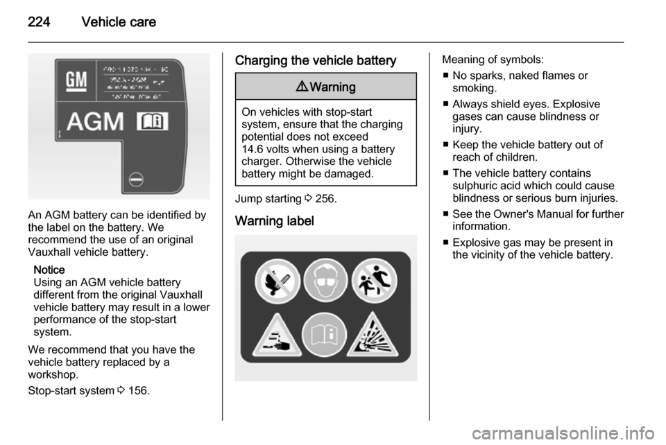
An AGM battery can be identified by
the label on the battery. We
recommend the use of an original
Vauxhall vehicle battery.
Notice
Using an AGM vehicle battery
different from the original Vauxhall
vehicle battery may result in a lower performance of the stop-start
system.
We recommend that you have the
vehicle battery replaced by a
workshop.
Stop-start system 3 156.
Charging the vehicle battery9 Warning
On vehicles with stop-start
system, ensure that the charging potential does not exceed
14.6 volts when using a battery
charger. Otherwise the vehicle
battery might be damaged.
Jump starting 3 256.
Warning label
Meaning of symbols: ■ No sparks, naked flames or smoking.
■ Always shield eyes. Explosive gases can cause blindness or
injury.
■ Keep the vehicle battery out of reach of children.
■ The vehicle battery contains sulphuric acid which could cause
blindness or serious burn injuries.
■ See the Owner's Manual for further
information.
■ Explosive gas may be present in the vicinity of the vehicle battery.
Page 238 of 293

236Vehicle careEngine compartment fuse
box
The fuse box is in the front left of the
engine compartment.
Disengage the cover and fold it
upwards until it stops. Remove the
cover vertically upwards.
No.Circuit1Engine control module2Lambda sensor3Fuel injection, ignition system4Fuel injection, ignition system5–6Mirror heating, anti-theft alarm
system7Fan control, engine control
module, transmission control
module8Lambda sensor, engine cooling9Rear window sensor10Battery sensor11Trunk release12Adaptive forward lighting, auto‐
matic light control13ABS14Rear window wiper
Page 250 of 293

248Vehicle care
4.Screw the compressor air hose to
the connection on the sealant
bottle.
5. Fit the sealant bottle into the retainer on the compressor.
Set the compressor near the tyre
in such a way that the sealant
bottle is upright.
6. Unscrew valve cap from defective
tyre.
7. Screw the filler hose to the tyre valve.
8. The switch on the compressor must be set to J.
9. Connect the compressor plug to
the power outlet or cigarette
lighter socket.
To avoid discharging the battery,
we recommend running the
engine.
10. Set the rocker switch on the compressor to I. The tyre is filled
with sealant.
11. The compressor pressure gauge briefly indicates up to 6 bar whilstthe sealant bottle is emptying
(approx. 30 seconds). Then the
pressure starts to drop.
12. All of the sealant is pumped into the tyre. Then the tyre is inflated.
13. The prescribed tyre pressure should be obtained within
10 minutes. Tyre pressure
3 279 . When the correct pressure
is obtained, switch off the
compressor.
If the prescribed tyre pressure is
not obtained within 10 minutes,
remove the tyre repair kit. Move
the vehicle one tyre rotation.
Reattach the tyre repair kit and
continue the filling procedure for
10 minutes. If the prescribed tyre
pressure is still not obtained, the
Page 258 of 293

256Vehicle careJump startingDo not start with quick charger.
A vehicle with a discharged battery
can be started using jump leads and the battery of another vehicle.9 Warning
Be extremely careful when starting
with jump leads. Any deviation
from the following instructions can
lead to injuries or damage caused
by battery explosion or damage to the electrical systems of both
vehicles.
9 Warning
Avoid contact of the battery with
eyes, skin, fabrics and painted
surfaces. The fluid contains
sulphuric acid which can cause
injuries and damage in the event
of direct contact.
■ Never expose the battery to naked flames or sparks.
■ A discharged battery can alreadyfreeze at a temperature of 0 °C.
Defrost the frozen battery before
connecting jump leads.
■ Wear eye protection and protective
clothing when handling a battery.
■ Use a booster battery with the same voltage (12 Volts). Its
capacity (Ah) must not be much less than that of the discharged
battery.
■ Use jump leads with insulated terminals and a cross section of at
least 16 mm 2
(25 mm 2
for diesel
engines).
■ Do not disconnect the discharged battery from the vehicle.
■ Switch off all unnecessary electrical
consumers.
■ Do not lean over the battery during jump starting.
■ Do not allow the terminals of one lead to touch those of the other
lead.
■ The vehicles must not come into contact with each other during the
jump starting process.■ Apply the parking brake, transmission in neutral, automatictransmission in P.
■ Open the positive terminal protection caps of both batteries.
Lead connection order:
1. Connect the red lead to the positive terminal of the booster
battery.
2. Connect the other end of the red lead to the positive terminal of the
discharged battery.