Page 189 of 344

187
Running out of fuel (Diesel)
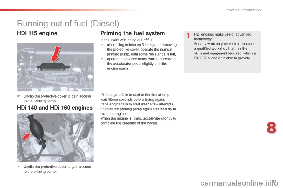
F Unclip the protective cover to gain access to the priming pump.
F
U
nclip the protective cover to gain access
to the priming pump.
Priming the fuel system
In the event of running out of fuel:
F a fter filling (minimum 5 litres) and removing
the protective cover, operate the manual
priming pump, until some resistance is felt,
F
o
perate the starter motor while depressing
the accelerator pedal slightly until the
engine starts. HDi engines make use of advanced
technology.
For any work on your vehicle, contact
a qualified workshop that has the
skills and equipment required, which a
CITROËN dealer is able to provide.
If the engine fails to start at the first attempt,
wait fifteen seconds before trying again.
If the engine fails to start after a few attempts,
operate the priming pump again and then try to
start the engine.
When the engine is idling, accelerate slightly to
complete the bleeding of the circuit.
HDi 115 engine
HDi 140 and HDi 160 engines
8
Practical information
Page 191 of 344
189
Using the kit
F Switch off the ignition.
F A ffix the speed limitation sticker to the
vehicle's steering wheel to remind you that
a wheel is in temporary use. F
C heck that the switch A is in position "0"
.
F C onnect the pipe of the cartridge 1 to the
valve of the tyre to be repaired. F
C onnect the compressor's electric plug to
the vehicle's 12 V socket.
F
S
tart the vehicle and leave the engine
running.
8
Practical information
Page 193 of 344

191
F Connect the compressor's electric plug to the vehicle's 12 V socket again.
F
S
tart the vehicle again and leave the
engine running. F
A djust the pressure using the compressor
(to inflate: switch A in position "1";
to
deflate: switch A in position "0" and
press button B ), in accordance with the
vehicle's tyre pressure label (located on
the door aperture on the left-hand side),
then remember to check that the leak has
been plugged correctly (no further loss of
pressure after several miles [kilometres]).
F
R
emove the compressor, then store the
whole kit.
F
D
rive at reduced speed (50 mph
[80
km/h] max) limiting the distance
travelled to approximately 120 miles
(200
km).
F
V
isit a CITROËN dealer or a qualified
workshop as soon as possible to have the
tyre repaired or replaced by a technician. Take care as sealant cartridge contains
ethylene-glycol. This product is harmful
if swallowed and causes irritation to the
eyes. Keep it out of reach of children.
The expiry date of the sealant is
indicated on the base of the cartridge.
The cartridge is designed for a single
use; even if only partly used, it must be
replaced.
After use, do not discard the cartridge
into the environment, take it to a
CITROËN dealer or an authorised
waste disposal site.
Do not forget to obtain a new cartridge,
available from CITROËN dealers or a
qualified workshop.
If the vehicle is fitted with tyre under-
inflation detection, the tyre under-
inflation warning lamp will remain on
after the wheel has been repaired until
the system is reinitialised by a CITROËN
dealer or a qualified workshop.
8
Practical information
Page 196 of 344

194
Removing a wheel
F Park the vehicle on stable, firm ground that is not slippery. apply the parking brake.
F
I
f your vehicle is equipped with
"Hydractive
III+" suspension, with the
engine running at idle, adjust the ground
clearance to its maximum height.
F
S
witch off the ignition and engage first gear
(position R for an electronic gearbox; P for
an automatic gearbox).
F
I
f your vehicle is fitted with "Hydractive III+"
suspension, position the chock, whichever
direction the gradient may be in, in front of
the front wheel diametrically opposite to
the one to be replaced.
List of operations
F Remove the protector from each bolt using tool 3 .
F
F
it the security bolt socket to the
wheelbrace to slacken the security bolt
(depending on equipment).
F
S
lacken the other bolts using just the
wheelbrace 1 .
Before positioning the jack:
F
A
lways adjust the vehicle’s ground
clearance to the "maximum height"
position and retain this adjustment
for as long as the jack is under the
vehicle (do not use the hydraulic
adjustments),
F
E
nsure that any passengers have
left the vehicle and are in a safe
place.
Never get underneath the vehicle if it is
supported only by the jack.
The jack and all of the tools are specific
to your vehicle. Do not use them for any
other applications.
Have the original wheel repaired and
refitted as soon as possible.
Practical information
Page 215 of 344

213
Fusebox C
Fuse N°Rating Function
F1 15 ARear screen wipe (Tourer)
F2 30 ALocking and deadlocking relay
F3 5 AAirbags
F4 10 AAutomatic gearbox - additional heater unit (Diesel) - electrochrome rear view mirror
F5 30 AFront window - sunroof - passenger door lighting - passenger door mirror adjustment
F6 30 ARear window
F7 5 AVanity mirror lighting - Glove box lighting - interior lamps - torch (tourer)
F8 20 ARadio - CD changer - Steering mounted controls - Screen - Under-inflation detection - Electric boot ECU
F9 30 ACigarette lighter - front 12 V socket
F10 15 AAlarm - Steering mounted controls, signalling and wiper controls
F11 15 ALow current ignition switch
F12 15 ADriver’s electric seat - instrument panel - seat belt not fastened warning lamps - air conditioning controls
F13 5 AEngine relay unit - Hydraulic suspension pump cut-off relay - airbag ECU supply
F14 15 ARain and sunshine sensor - parking sensors - passenger’s electric seat - trailer relay unit - HIFI amplifier ECU -
Bluetooth system - Lane Departure Warning System
F15 30 ALocking and deadlocking relay
F17 40 AHeated rear screen - Heated door mirrors
FSH SHUNTPARK SHUNT
8
Practical information
Page 216 of 344

214
Fuses under the bonnet
Access to the fuses
F Undo each screw by a 1/4 turn.
F R emove the cover.
F
R
eplace the fuse. Fuse N°
Rating Function
F1 20 AEngine control unit
F2 15 AHorn
F3 10 AScreen wash pump
F4 10 AHeadlamp wash pump
F5 15 AStarter
F6 10 AAir flow sensor - Directional headlamps - Diagnostic socket
F7 10 AAutomatic gear lever lock - Power steering
F8 25 AStarter motor
F9 10 AClutch switch - S
T
o
P s
witch
F10 30 AActuator motors
F11 40 AAir conditioning blower
F12 30 AWipers
F13 40 ABSI supply (ignition on)
F14 30 A-
F15 10 ARight-hand main beam
F16 10 ALeft-hand main beam
F17 15 ARight-hand dipped beam
F18 15 ALeft-hand dipped beam
F19 15 AActuator motors
F20 10 AActuator motors
F21 5 AActuator motors
On completion, carefully refit the
cover to ensure correct sealing of
the fusebox.
Any work on the MA XI fuses (that
give additional protection), located
in the fuseboxes, must be left to
a CITROËN dealer or a qualified
workshop.
Table of fuses
Practical information
Page 218 of 344
216
battery
Access to the battery
The battery is located under the bonnet.
For access to it:
F
o
pen the bonnet using the interior release
lever, then the exterior safety catch,
F
s
ecure the bonnet stay,
F
r
emove the plastic cover to gain access to
the two terminals,
F
u
nclip the fusebox to remove the battery,
if
necessary.
The presence of this label, in particular
with the Stop & Start system, indicates
the use of a 12 V lead-acid battery with
special technology and specification;
the involvement of a CITROËN dealer
or a qualified workshop is essential
when replacing or disconnecting the
battery.
After refitting the battery, the Stop &
Start system will only be active after a
continuous period of immobilisation of the
vehicle, a period which depends on the
climatic conditions and the state of charge
of the battery (up to about 8 hours).
Procedure for charging your battery when it is flat or for starting the engine using another battery.
Practical information
Page 219 of 344

217
Following reconnection of
the battery
Following reconnection of the battery,
switch on the ignition and wait 1 minute
before starting to permit initialisation
of the electronic systems. However, if
slight malfunctions remain following this
operation, contact a CITROËN dealer
or a qualified workshop.
Referring to the corresponding section,
you must yourself reinitialise:
-
t
he remote control key,
-
t
he glass panoramic roof blind,
-
t
he GPS satellite navigation
system.
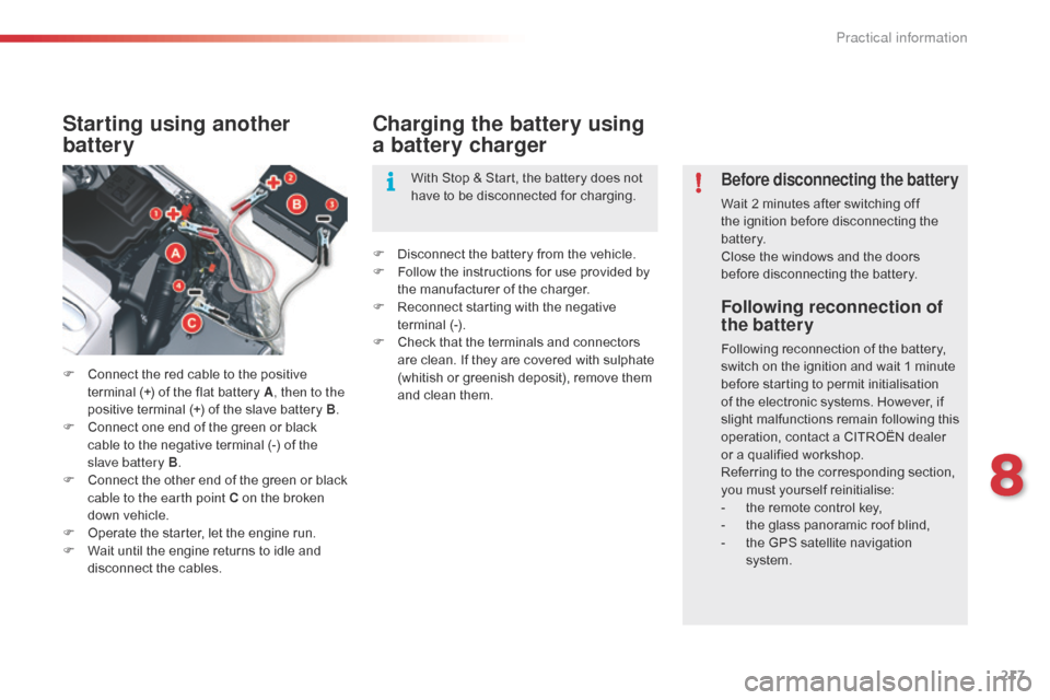
Starting using another
battery
F Connect the red cable to the positive terminal (+) of the flat battery A , then to the
positive terminal (+) of the slave battery B.
F
C
onnect one end of the green or black
cable to the negative terminal (-) of the
slave battery B .
F
C
onnect the other end of the green or black
cable to the earth point C on the broken
down vehicle.
F
O
perate the starter, let the engine run.
F
W
ait until the engine returns to idle and
disconnect the cables.
Charging the battery using
a battery charger
F Disconnect the battery from the vehicle.
F F ollow the instructions for use provided by
the manufacturer of the charger.
F
R
econnect starting with the negative
terminal (-).
F
C
heck that the terminals and connectors
are clean. If they are covered with sulphate
(whitish or greenish deposit), remove them
and clean them. With Stop & Start, the battery does not
have to be disconnected for charging.
Before disconnecting the battery
Wait 2 minutes after switching off
the ignition before disconnecting the
battery.
Close the windows and the doors
before disconnecting the battery.
8
Practical information