2013 YAMAHA YZ450F fuel pump
[x] Cancel search: fuel pumpPage 10 of 228

CONTENTS
CHAPTER 1
GENERAL INFOR-
MATION
LOCATION OF
IMPORTANT LABELS ..... 1-1
DESCRIPTION ................. 1-5
CONSUMER
INFORMATION................. 1-6
FEATURES....................... 1-7
INCLUDED PARTS .......... 1-9
IMPORTANT
INFORMATION................. 1-9
HANDLING THE
ELECTRONIC PARTS ... 1-10
CHECKING OF
CONNECTION ................ 1-10
SPECIAL TOOLS ........... 1-12
CONTROL
FUNCTIONS ................... 1-17
STARTING
AND BREAK-IN.............. 1-17
TORQUE-CHECK
POINTS........................... 1-19
CLEANING
AND STORAGE ............. 1-20
CHAPTER 2
SPECIFICATIONS
GENERAL
SPECIFICATIONS ............ 2-1
MAINTENANCE
SPECIFICATIONS ............ 2-3
TIGHTENING
TORQUES ...................... 2-11
LUBRICATION
DIAGRAMS .................... 2-17
CABLE ROUTING
DIAGRAM ....................... 2-18
CHAPTER 3
REGULAR INSPEC-
TION AND AD-
JUSTMENTS
MAINTENANCE
INTERVALS ...................... 3-1
PRE-OPERATION
INSPECTION
AND MAINTENANCE ....... 3-5
ENGINE ............................ 3-6
CHASSIS ........................ 3-14
ELECTRICAL ................. 3-24
CHAPTER 4
ENGINE
SEAT
AND SIDE COVERS ......... 4-1
EXHAUST PIPE
AND SILENCER ............... 4-3
RADIATOR ....................... 4-5
CAMSHAFTS.................... 4-8
CYLINDER HEAD........... 4-13
VALVES AND
VALVE SPRINGS ........... 4-17
CYLINDER
AND PISTON .................. 4-21
CLUTCH ......................... 4-25
OIL FILTER ELEMENT
AND WATER PUMP ....... 4-29
BALANCER .................... 4-33
OIL PUMP ....................... 4-35
KICK SHAFT
AND SHIFT SHAFT ........ 4-38
AC MAGNETO................ 4-43
ENGINE REMOVAL ....... 4-45
CRANKCASE
AND CRANKSHAFT ...... 4-50
TRANSMISSION,
SHIFT CAM
AND SHIFT FORK .......... 4-56
CHAPTER 5
CHASSIS
FRONT WHEEL
AND REAR WHEEL .........5-1
FRONT BRAKE
AND REAR BRAKE..........5-6
FRONT FORK .................5-16
HANDLEBAR..................5-24
STEERING ......................5-28
SWINGARM ....................5-32
REAR
SHOCK ABSORBER ......5-37
CHAPTER 6
FUEL SYSTEM
FUEL TANK ......................6-1
THROTTLE BODY ............6-4
CHAPTER 7
ELECTRICAL
ELECTRICAL
COMPONENTS AND
WIRING DIAGRAM ...........7-1
IGNITION SYSTEM...........7-3
THROTTLE POSITION
SENSOR SYSTEM ...........7-6
FUEL INJECTION
SYSTEM............................7-9
FUEL PUMP SYSTEM ....7-35
ELECTRICAL
COMPONENTS...............7-36
CHAPTER 8
TUNING
CHASSIS ..........................8-1
Page 17 of 228

1-7
FEATURES
FEATURES
OUTLINE OF THE FI SYSTEM
The main function of a fuel supply system is to provide fuel to the combustion chamber at the optimum air-fuel ratio in ac-
cordance with the engine operating conditions and the atmospheric temperature. In the conventional carburetor system,
the air-fuel ratio of the mixture that is supplied to the combustionchamber is created by the volume of the intake air and the
fuel that is metered by the jet used in the respective carburetor.
Despite the same volume of intake air, the fuel volume requirement varies by the engine operating conditions,such as ac-
celeration, deceleration, or operating under a heavy load. Carburetors that meter thefuel through the use of jets have been
provided with various auxiliary devices, so that an optimum air-fuel ratio can be achieved to accommodate the constant
changes in the operating conditions of the engine.
This model has adopted an electronically controlled fuel injection (FI) system, in place of the conventional carburetor sys-
tem. This system can achieve an optimum air-fuel ratio required bythe engine at all times by using a microprocessor that
regulates the fuel injection volume according tothe engine operating conditions detected by various sensors.
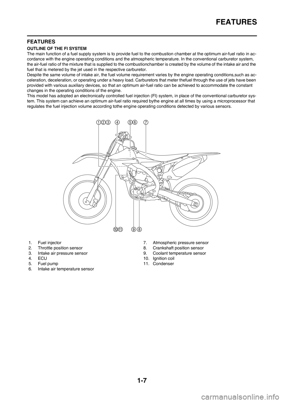
1. Fuel injector
2. Throttle position sensor
3. Intake air pressure sensor
4. ECU
5. Fuel pump
6. Intake air temperature sensor7. Atmospheric pressure sensor
8. Crankshaft position sensor
9. Coolant temperature sensor
10. Ignition coil
11. Condenser
Page 18 of 228

1-8
FEATURES
FI SYSTEM
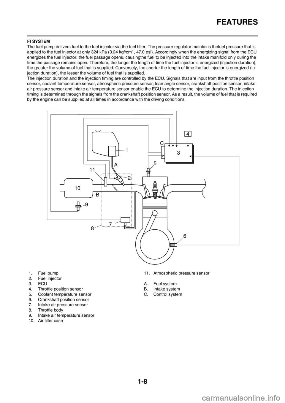
The fuel pump delivers fuel to the fuel injector via the fuel filter. The pressure regulator maintains thefuel pressure that is
applied to the fuel injector at only 324 kPa (3.24 kgf/cm², 47.0 psi). Accordingly,when the energizing signal from the ECU
energizes the fuel injector, the fuel passage opens, causingthe fuel to be injected into the intake manifold only during the
time the passage remains open. Therefore, the longer the length of time the fuel injector is energized (injection duration),
the greater the volume of fuel that is supplied. Conversely, the shorter the length of time the fuel injector is energized (in-
jection duration), the lesser the volume of fuel that is supplied.
The injection duration and the injection timing are controlled by the ECU. Signals that are input from the throttle position
sensor, coolant temperature sensor, atmospheric pressure sensor, lean angle sensor, crankshaft position sensor, intake
air pressure sensor and intake air temperature sensor enable the ECU to determine the injection duration. The injection
timing is determined through the signals from the crankshaft position sensor. As a result, the volume of fuel that is required
by the engine can be supplied at all times in accordance with the driving conditions.
1. Fuel pump
2. Fuel injector
3. ECU
4. Throttle position sensor
5. Coolant temperature sensor
6. Crankshaft position sensor
7. Intake air pressure sensor
8. Throttle body
9. Intake air temperature sensor
10. Air filter case11. Atmospheric pressure sensor
A. Fuel system
B. Intake system
C. Control system
1
10
9B
87
6 5
A
23 C4
11
Page 19 of 228

1-9
INCLUDED PARTS
INCLUDED PARTS
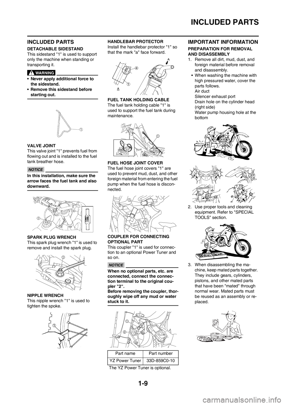
DETACHABLE SIDESTAND
This sidestand "1" is used to support
only the machine when standing or
transporting it.
• Never apply additional force to
the sidestand.
• Remove this sidestand before
starting out.
VALVE JOINT
This valve joint "1" prevents fuel from
flowing out and is installed to the fuel
tank breather hose.
In this installation, make sure the
arrow faces the fuel tank and also
downward.
SPARK PLUG WRENCH
This spark plug wrench "1" is used to
remove and install the spark plug.
NIPPLE WRENCH
This nipple wrench "1" is used to
tighten the spoke.HANDLEBAR PROTECTOR
Install the handlebar protector "1" so
that the mark "a" face forward.
FUEL TANK HOLDING CABLE
The fuel tank holding cable "1" is
used to support the fuel tank during
maintenance.
FUEL HOSE JOINT COVER
The fuel hose joint covers "1" are
used to prevent mud, dust, and other
foreign material from entering the fuel
pump when the fuel hose is discon-
nected.
COUPLER FOR CONNECTING
OPTIONAL PART
This coupler "1" is used for connec-
tion to an optional Power Tuner and
so on.
When no optional parts, etc. are
connected, connect the connec-
tion terminal to the original cou-
pler "2".
Before removing the coupler, thor-
oughly wipe off any mud or water
stuck to it.
IMPORTANT INFORMATION
PREPARATION FOR REMOVAL
AND DISASSEMBLY
1. Remove all dirt, mud, dust, and
foreign material before removal
and disassembly.
• When washing the machine with
high pressured water, cover the
parts follows.
Air duct
Silencer exhaust port
Drain hole on the cylinder head
(right side)
Water pump housing hole at the
bottom
2. Use proper tools and cleaning
equipment. Refer to "SPECIAL
TOOLS" section.
3. When disassembling the ma-
chine, keep mated parts together.
They include gears, cylinders,
pistons, and other mated parts
that have been "mated" through
normal wear. Mated parts must
be reused as an assembly or re-
placed.
Part name Part number
YZ Power Tuner 33D-859C0-10
The YZ Power Tuner is optional.
Page 27 of 228

1-17
CONTROL FUNCTIONS
CONTROL FUNCTIONS
ENGINE STOP SWITCH
The engine stop switch "1" is located
on the left handlebar. Continue push-
ing the engine stop switch till the en-
gine comes to a stop.
CLUTCH LEVER
The clutch lever "1" is located on the
left handlebar; it disengages or en-
gages the clutch. Pull the clutch lever
to the handlebar to disengage the
clutch, and release the lever to en-
gage the clutch. The lever should be
pulled rapidly and released slowly for
smooth starts.
SHIFT PEDAL
The gear ratios of the constant-mesh
5 speed transmission are ideally
spaced. The gears can be shifted by
using the shift pedal "1" on the left
side of the engine.
KICKSTARTER CRANK
Rotate the kickstarter crank "1" away
from the engine. Push the starter
down lightly with your foot until the
gears engage, then kick smoothly
and forcefully to start the engine. This
model has a primary kickstarter crank
so the engine can be started in any
gear if the clutch is disengaged. In
normal practices, however, shift to
neutral before starting.THROTTLE GRIP
The throttle grip "1" is located on the
right handlebar; it accelerates or de-
celerates the engine. For accelera-
tion, turn the grip toward you; for
deceleration, turn it away from you.
FRONT BRAKE LEVER
The front brake lever "1" is located on
the right handlebar. Pull it toward the
handlebar to activate the front brake.
REAR BRAKE PEDAL
The rear brake pedal "1" is located on
the right side of the machine. Press
down on the brake pedal to activate
the rear brake.
STARTER KNOB/IDLE SCREW
The starter knob/idle screw "1" is
used when starting a cold engine.
Pull the starter knob/idle screw out to
open the circuit for starting. When the
engine has warmed up, push it in to
close the circuit.
STARTING AND BREAK-IN
FUEL
Always use the recommended fuel as
stated below. Also, be sure to use
new gasoline the day of a race.
Use only unleaded gasoline. The
use of leaded gasoline will cause
severe damage to the engine inter-
nal parts such as valves, piston
rings, and exhaust system, etc.
Your Yamaha engine has been de-
signed to use premium unleaded gas-
oline with a pump octane number
[(R+M)/2] of 91 or higher, or a re-
search octane number of 95 or high-
er. If knocking (or pinging) occurs,
use a gasoline of a different brand.
• For refueling, be sure to stop the
engine and use enough care not
to spill any fuel. Also be sure to
avoid refueling close to a fire.
• Refuel after the engine, exhaust
pipe, etc. have cooled off.
Gasohol (For USA and Canada)
There are two types of gasohol: gas-
ohol containing ethanol and that con-
taining methanol. Gasohol containing
ethanol can be used if the ethanol
content does not exceed 10%. Gaso-
hol containing methanol is not recom-
mended by Yamaha because it can
cause damage to the fuel system or
vehicle performance problems.
HANDLING NOTE
Never start or run the engine in a
closed area. The exhaust fumes
are poisonous; they can cause
loss of consciousness and death
in a very short time. Always oper-
ate the machine in a well-ventilated
area.
Recommended fuel:
Premium unleaded
gasoline only
Page 29 of 228

1-19
TORQUE-CHECK POINTS
TORQUE-CHECK POINTS
Concerning the tightening torque, refer to "TIGHTENING TORQUES" section in the CHAPTER 2.
Frame construction Frame to rear frame
Combined seat and fuel tank Fuel tank to frame
Exhaust system Silencer to rear frame
Engine mounting Frame to engine
Engine bracket to engine
Engine bracket to frame
Steering Steering stem to handlebar Steering stem to frame
Steering stem to upper bracket
Upper bracket to handlebar
Suspension Front Steering stem to front fork Front fork to upper bracket
Front fork to lower bracket
Rear For link type Assembly of links
Link to frame
Link to rear shock absorber
Link to swingarm
Installation of rear shock absorber Rear shock absorber to frame
Installation of swingarm Tightening of pivot shaft
Wheel Installation of wheel Front Tightening of wheel axle
Tightening of axle holder
Rear Tightening of wheel axle
Wheel to rear wheel sprocket
Brake Front Brake caliper to front fork
Brake disc to wheel
Tightening of union bolt
Brake master cylinder to handlebar
Tightening of bleed screw
Tightening of brake hose holder
Rear Brake pedal to frame
Brake disc to wheel
Tightening of union bolt
Brake master cylinder to frame
Tightening of bleed screw
Tightening of brake hose holder
Fuel system Fuel pump to fuel tank
Page 37 of 228

2-7
MAINTENANCE SPECIFICATIONS
Crankshaft:
Crank width "A" 61.95–62.00 mm (2.439–2.441 in) ----
Runout limit "C" 0.03 mm (0.0012 in) 0.05 mm (0.002
in)
Big end side clearance "D" 0.15–0.45 mm (0.0059–0.0177 in) 0.50 mm (0.02
in)
Small end free play "F" 0.4–1.0 mm (0.02–0.04 in) 2.0 mm (0.08
in)
Balancer:
Balancer drive method Gear ----
Air filter oil grade: Foam-air-filter oil or equivalent oil ----
Clutch:
Friction plate thickness 2.92–3.08 mm (0.115–0.121 in) 2.8 mm (0.110
in)
Quantity 8 ----
Clutch plate thickness 1.5–1.7 mm (0.059–0.067 in) ----
Quantity 7 ----
Warp limit ---- 0.1 mm (0.004
in)
Clutch spring free length 50.0 mm (1.97 in) 49.0 mm (1.93
in)
Quantity 6 ----
Clutch housing thrust clearance 0.10–0.35 mm (0.0039–0.0138 in) ----
Clutch housing radial clearance 0.010–0.044 mm (0.0004–0.0017 in) ----
Clutch release method Inner push, cam push ----
Shifter:
Shifter type Cam drum and guide bar ----
Guide bar bending limit ---- 0.05 mm (0.002
in)
Kickstarter:
Type Kick and ratchet type ----
Fuel pump:
Fuel pressure 324 kPa (3.24 kg/cm
2, 46.1 psi) ----
Fuel injector:----
Model/manufacturer 1010/DENSO ----
Throttle body:----
I. D. mark 33D1 00 ----
Manufacturer KEIHIN ----Item Standard Limit
Page 38 of 228

2-8
MAINTENANCE SPECIFICATIONS
Throttle position sensor:----
Throttle position sensor maximum resistance 5 kΩ----
Throttle position sensor variable resistance 0–2 kΩ (full closed) ----
Throttle position sensor input voltage 4–6 V ----
Fuel injection sensor:----
Crankshaft position sensor resistance 248–372 Ω----
Intake air pressure sensor output voltage 3.57–3.71 V at 101.3kPa (1.013 kg/cm
2,
14.41 psi)----
Atmospheric pressure sensor output voltage 3.57–3.71 V at 101.3kPa (1.013 kg/cm
2,
14.41 psi)----
Intake air temperature sensor 5.4–6.6 kΩat 0 °C (32 °F)
290–390 Ωat 80 °C (176 °F)----
Idling condition:----
Engine idle speed 1,900–2,100 r/min ----
Oil temperature 55–65 °C (131–149 °F) ----
Lubrication system:
Oil filter type Paper type ----
Oil pump type Trochoid type ----
Tip clearance 0.12 mm or less (0.0047 in or less) 0.20 mm (0.008
in)
Side clearance 0.09–0.17 mm (0.0035–0.0067 in) 0.24 mm (0.009
in)
Housing and rotor clearance 0.03–0.10 mm (0.0012–0.0039 in) 0.17 mm
(0.0067 in)
Bypass valve setting pressure 40–80 kPa (0.4–0.8 kg/cm
2, 5.69–11.38
psi)----
Cooling:
Radiator core size
Width 121.4 mm (4.78 in) ----
Height 235 mm (9.25 in) ----
Thickness 28 mm (1.10 in) ----
Radiator cap opening pressure 108–137 kPa (1.08–1.37 kg/cm
2, 15.4–
19.5 psi)----
Radiator capacity (total) 0.62 L (0.55 Imp qt, 0.66 US qt) ----
Water pump
Type Single-suction centrifugal pump ----Item Standard Limit