2013 YAMAHA VXR remote control
[x] Cancel search: remote controlPage 5 of 98

Table of contents
General and important labels ........... 1Identification numbers .................... 1
Primary Identification (PRI-ID)
number ........................................... 1
Craft Identification Number (CIN) ...... 1
Engine serial number ........................ 1
Manufactured date label .................... 2
Model information ........................... 2
Builder’s plate .................................... 2
Important labels .............................. 4
Warning labels ................................... 5
Other labels ....................................... 8
Safety information ........................... 10 Limitations on who may operate the watercraft ............................ 10
Cruising limitations ....................... 11
Operation requirements ............... 12
Recommended equipment ........... 14
Hazard information ....................... 15
Watercraft characteristics ............. 15
Water-skiing ................................. 17
Safe boating rules ........................ 18
Enjoy your watercraft responsibly ................................ 19
Description....................................... 20 Watercraft glossary ...................... 20
Location of main components ...... 21
Control function operation ............. 25 Watercraft control functions ......... 25
Remote control transmitter .............. 25
Yamaha Security System ................ 26
Engine stop switch .......................... 27
Engine shut-off switch ..................... 27
Start switch ...................................... 27
Throttle lever ................................... 28
Steering system ............................... 28
Cooling water pilot outlet ................. 29
Water separator ............................... 29
Watercraft operation ....................... 30Watercraft operation functions ..... 30
Reverse system ............................... 30
Watercraft operation modes ......... 31
Low RPM Mode ............................... 31
Instrument operation ...................... 33Multifunction information center ... 33
Information display .......................... 33
Equipment operation ...................... 38Equipment .................................... 38
Seat ................................................. 38
Handgrip .......................................... 39
Reboarding step (VXR) ................... 39
Bow eye ........................................... 39
Stern eyes ....................................... 40
Cleat ................................................ 40
Storage compartments .................... 40
Fire extinguisher holder and
cover ............................................ 42
Operation and handling
requirements ................................... 44Fuel requirements ........................ 44
Fuel ................................................. 44
Engine oil requirements ............... 45
Engine oil ......................................... 45
Draining the bilge water ............... 47
Draining the bilge water on land ...... 47
Draining the bilge water on water .... 47
Transporting on a trailer ............... 48
First-time operation ........................ 49 Engine break-in ............................ 49
Pre-operation checks ..................... 50
Pre-operation checklist .................... 50
Pre-operation check points .......... 52
Pre-launch checks ........................... 52
Post-launch checks ......................... 58
UF2M72E0.book Page 1 Thursday, July 12, 2012 5:05 PM
Page 15 of 98

General and important labels
9
The following label indicates the correct direction to upright a capsized watercraft.
The following CE marking is located on the back of the remote control transmitter.
UF2M72E0.book Page 9 Thursday, July 12, 2012 5:05 PM
Page 29 of 98

Description
23
5
4
1
2 3
10
1112
7
6
8
9
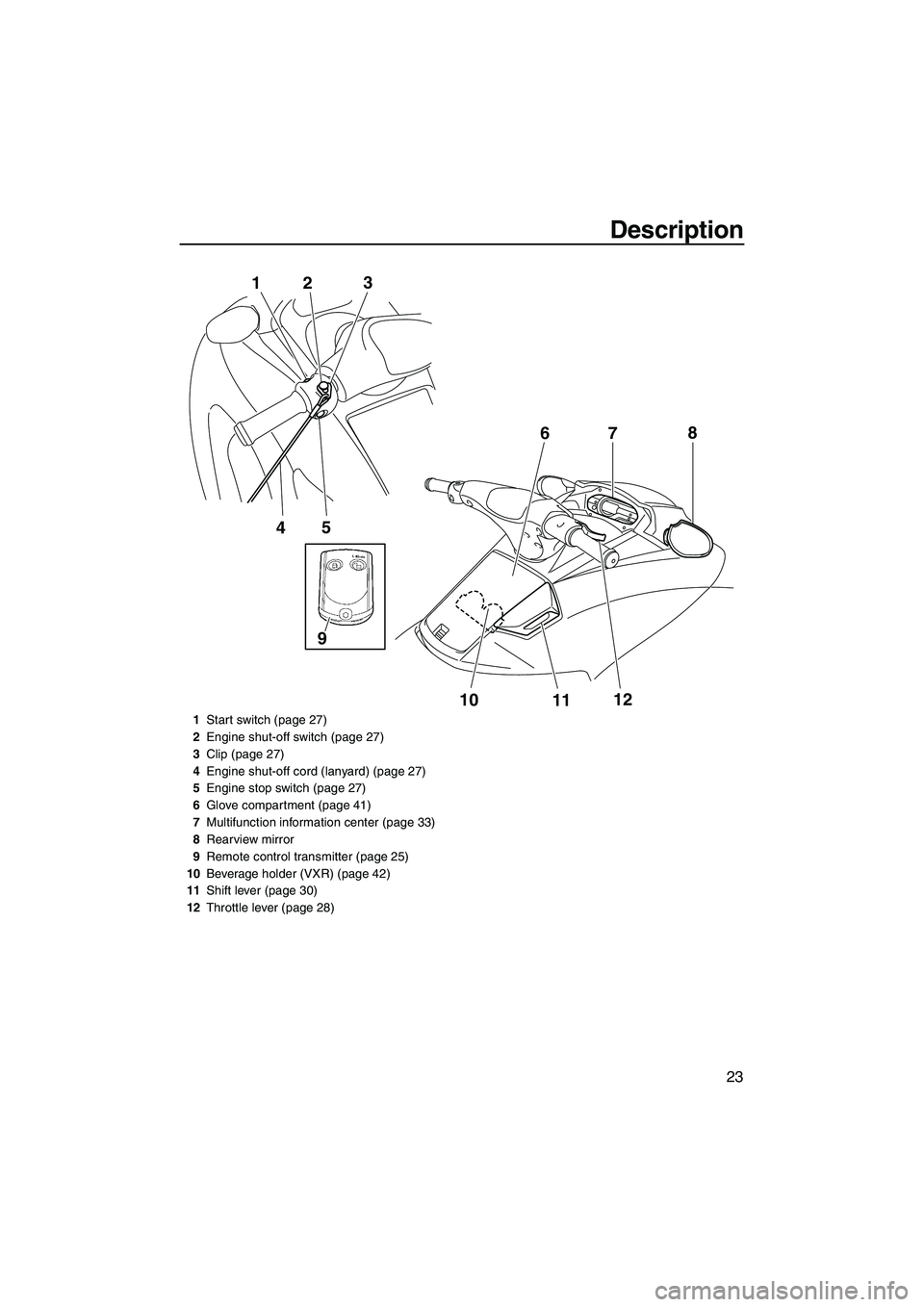
1
Start switch (page 27)
2 Engine shut-off switch (page 27)
3 Clip (page 27)
4 Engine shut-off cord (lanyard) (page 27)
5 Engine stop switch (page 27)
6 Glove compartment (page 41)
7 Multifunction information center (page 33)
8 Rearview mirror
9 Remote control transmitter (page 25)
10 Beverage holder (VXR) (page 42)
11 Shift lever (page 30)
12 Throttle lever (page 28)
UF2M72E0.book Page 23 Thursday, July 12, 2012 5:05 PM
Page 31 of 98

Control function operation
25
EJU31024
Watercraft control functions EJU41931Remote control transmitter
The Yamaha Security System and Low RPM
Mode settings can be selected by operating
the remote control transmitter. (See page 26
for Yamaha Security System setting proce-
dures and page 31 for Low RPM Mode activa-
tion procedures.)
Since the watercraft is programmed to recog-
nize the internal code from this transmitter
only, the settings can only be selected with
this transmitter.
If you accidentally lose your remote control
transmitter or if it is not operating properly,
contact a Yamaha dealer.
When operating the watercraft, always keep
the transmitter with you so that it is not lost. VXR: This watercraft is equipped with a trans-
mitter holder in the beverage holder.
NOTICE
ECJ00752
●The remote control transmitter is not
completely waterproof. Do not sub-
merge the transmitter or operate it un-
derwater. If the transmitter is
submerged, dry it with a soft, dry cloth,
and then check that it is operating prop-
erly. If the transmitter is not operating
properly, contact a Yamaha dealer.
●Keep the remote control transmitter
away from high temperatures and do not
place it in direct sunlight.
●Do not drop the remote control transmit-
ter, subject it to strong shocks, or place
any heavy items on it.
●Use a soft, dry cloth to clean the remote
control transmitter. Do not use deter-
gent, alcohol, or other chemicals.
●Do not attempt to disassemble the re-
mote control transmitter yourself. Other-
wise, the transmitter may not operate
properly. If the transmitter needs a new
battery, contact a Yamaha dealer. Refer
to local hazardous waste regulations
when disposing of transmitter batteries.
1
Remote control transmitter
1Transmitter holder
1
UF2M72E0.book Page 25 Thursday, July 12, 2012 5:05 PM
Page 32 of 98

Control function operation
26
EJU31384Yamaha Security System
The Yamaha Security System functions to
help prevent unauthorized use or theft of the
watercraft. The lock and unlock modes of the
security system can be selected by operating
the remote control transmitter that is included
with this watercraft. The engine cannot be
started if the lock mode of the security system
is selected. The engine can only be started if
the unlock mode is selected. (See page 25 for
information on the remote control transmitter.)
TIP:
The Yamaha Security System settings can
only be selected while the engine is stopped.
EJU36106Yamaha Security System settings The Yamaha Security System settings will be
confirmed by the number of beeps when the
remote control transmitter is operated, and by
the “SECURITY” indicator light of the multi-
function information center. (See page 33 for
information on the multifunction information
center.)
TIP:
●The beeper sounds two times for the nor-
mal operation mode or three times for the
Low RPM Mode. (See page 31 for Low
RPM Mode activation procedures.)
●If the remote control transmitter is operated
while the multifunction information center is
in the standby state, the center will perform the initial operation, and then the setting is
selected.
To select the lock mode:
Push the lock button on the remote control
transmitter briefly. The beeper sounds once
and the “SECURITY” indicator light blinks
once, then goes off. This indicates the lock
mode is selected.
To select the unlock mode:
Push the “L-Mode” (unlock) button on the re-
mote control transmitter briefly. The beeper
sounds two or three times and the “SECURI-
TY” indicator light blinks two or three times,
then comes on. This indicates the unlock
mode is selected.
Number of beeps Yamaha Security
System mode “SECURI-
TY” indi-
cator light
Lock Goes off
Unlock
(normal operation mode) Comes
on
Unlock
(Low RPM Mode) Comes
on
1 Lock button
2 “SECURITY” indicator light
1 “L-Mode” (unlock) button
2 “SECURITY” indicator light
21
2L-Mode1
UF2M72E0.book Page 26 Thursday, July 12, 2012 5:05 PM
Page 37 of 98

Watercraft operation
31
EJU40000
Watercraft operation modes
EJU41960Low RPM Mode
The Low RPM Mode is a function that limits
the maximum engine speed to approximately
70% of the maximum engine speed in the nor-
mal mode.
The Low RPM Mode can only be activated
and deactivated by operating the remote con-
trol transmitter that is included with this water-
craft. (See page 25 for information on the
remote control transmitter.)
TIP:
The Low RPM Mode can only be activated
when the engine is stopped in the unlock
mode of the Yamaha Security System.
Activating and deactivating the Low RPM
Mode
Activation of the Low RPM Mode will be con-
firmed by the number of beeps when the re-
mote control transmitter is operated, and by
the “L-MODE” indicator light of the multifunc-
tion information center. (See page 33 for infor-
mation on the multifunction information
center.)
TIP:
If the remote control transmitter is operated
while the multifunction information center is in
the standby state, the center performs the ini-
tial operation, and then the setting is selected.
To activate the Low RPM Mode:
Push the “L-Mode” (unlock) button on the re-
mote control transmitter for more than 4 sec-
onds. Once the beeper sounds three times
and the “SECURITY” indicator light blinks
three times, then comes on, the “L-MODE” in-
dicator light comes on and the Low RPM
Mode is activated.
TIP:
If the Low RPM Mode is activated immediate-
ly after the information display turns off, the
“L-MODE” indicator light will not come on. The
1 Remote control transmitter
Number of
beeps Low RPM Mode
operation “L-
MODE”
indicator light
Activated Comes
on
Deactivated Goes off
UF2M72E0.book Page 31 Thursday, July 12, 2012 5:05 PM
Page 56 of 98

Pre-operation checks
50
EJU31981
WARNING
EWJ00411
Failure to inspect or maintain the watercraft properly increases the possibility of an ac-
cident or damage to the watercraft. Do not operate the watercraft if you find any prob-
lem. If a problem cannot be corrected by the procedures provided in this manual, have
the watercraft inspected by a Yamaha dealer.
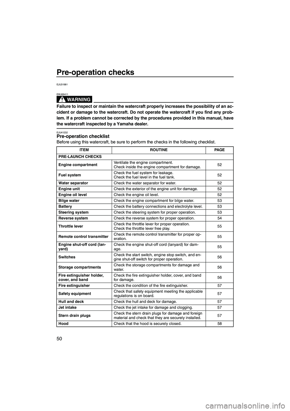
EJU41232Pre-operation checklist
Before using this watercraft, be sure to perform the checks in the following checklist.
ITEM ROUTINEPAGE
PRE-LAUNCH CHECKS
Engine compartment Ventilate the engine compartment.
Check inside the engine compartment for damage.
52
Fuel system Check the fuel system for leakage.
Check the fuel level in the fuel tank.
52
Water separator Check the water separator for water. 52
Engine unit Check the exterior of the engine unit for damage. 52
Engine oil level Check the engine oil level. 52
Bilge water Check the engine compartment for bilge water. 53
Battery Check the battery connections and electrolyte level. 53
Steering system Check the steering system for proper operation. 53
Reverse system Check the reverse system for proper operation. 54
Throttle lever Check the throttle lever for proper operation.
Check the throttle lever free play.
55
Remote control transmitter Check the remote control transmitter for proper op-
eration.
55
Engine shut-off cord (lan-
yard) Check the engine shut-off cord (lanyard) for dam-
age.
55
Switches Check the start switch, engine stop switch, and en-
gine shut-off switch for proper operation.
56
Storage compartments Check the storage compartments for damage and
water.
56
Fire extinguisher holder,
cover, and band Check the fire extinguisher holder, cover, and band
for damage.
56
Fire extinguisher Check the condition of the fire extinguisher. 57
Safety equipment Check that safety equipment meeting the applicable
regulations is on board.
57
Hull and deck Check the hull and deck for damage. 57
Jet intake Check the jet intake for damage and clogging. 57
Stern drain plugs Check the stern drain plugs for damage and foreign
material and check that they are securely installed.
57
Hood Check that the hood is securely closed. 58
UF2M72E0.book Page 50 Thursday, July 12, 2012 5:05 PM
Page 61 of 98

Pre-operation checks
55
Operate the shift lever several times to make
sure that operation is smooth throughout the
whole range. Also, make sure that the reverse
gate moves up and down according to the op-
eration of the shift lever and that the gate
makes contact with the stoppers. (See page
30 for reverse system operation.)
EJU32594Throttle lever checks
Operate the throttle lever several times to
make sure that operation is smooth through-
out the whole range. Also, make sure that thethrottle lever returns automatically to its fully
closed (idle) position when released.
Make sure that there is the proper amount of
throttle lever free play when the throttle lever
is in the fully closed (idle) position.EJU40112Remote control transmitter check
Make sure that the remote control transmitter
operates properly. (See page 26 for Yamaha
Security System setting procedures and page
31 for Low RPM Mode activation procedures.)
EJU32663Engine shut-off cord (lanyard) check
Make sure that the engine shut-off cord (lan-
yard) is not damaged. If the cord is damaged,
replace it.
WARNING! Never try to repair
the engine shut-off cord (lanyard) or tie it
together. The engine shut-off cord (lan-
1 Stopper
1
1Throttle lever free play
Throttle lever free play:
4.0–7.0 mm (0.16–0.28 in)
1
UF2M72E0.book Page 55 Thursday, July 12, 2012 5:05 PM