2013 YAMAHA TTR110 clutch
[x] Cancel search: clutchPage 9 of 88

TABLE OF CONTENTS
LOCATION OF IMPORTANT
LABELS ............................................1-1
SAFETY INFORMATION .................. 2-1
DESCRIPTION .................................. 3-1
Left view .......................................... 3-1
Right view ........................................ 3-2
Controls and instruments ................3-3
INSTRUMENT AND CONTROL
FUNCTIONS ....................................... 4-1
Main switch ..................................... 4-1
Handlebar switches ........................ 4-1
Shift pedal ......................................4-2
Brake lever ..................................... 4-2
Brake pedal .................................... 4-3
Fuel tank cap .................................. 4-3
Fuel ................................................ 4-3
Fuel tank breather hose ................. 4-6
Fuel cock ........................................ 4-6
Starter (choke) lever ....................... 4-7
Kickstarter ......................................4-8
Seat ................................................ 4-8
Shock absorber assembly .............. 4-9
Sidestand ....................................... 4-9
Starting circuit cut-off system ......... 4-9 FOR YOUR SAFETY –
PRE-OPERATION CHECKS
............. 5-1
OPERATION AND IMPORTANT
RIDING POINTS ................................ 6-1
Starting and warming up a cold engine ......................................... 6-1
Starting a warm engine .................. 6-2
Shifting ........................................... 6-2
Engine break-in .............................. 6-3
Parking ........................................... 6-4
PERIODIC MAINTENANCE AND
ADJUSTMENT ................................... 7-1
Owner’s tool kit .............................. 7-2
Periodic maintenance chart for the emission control system ............. 7-3
General maintenance and lubrication chart .......................... 7-4
Removing and installing panels ..... 7-7
Checking the spark plug ................ 7-8
Engine oil ....................................... 7-9
Cleaning the air filter element ...... 7-11
Cleaning the spark arrester ......... 7-13
Adjusting the carburetor ............... 7-14
Adjusting the engine idling
speed ........................................ 7-14
Checking the throttle grip free play ........................................... 7-15
Valve clearance ........................... 7-15
Tires ............................................. 7-15 Spoke wheels ............................... 7-17
Adjusting the clutch free play ....... 7-17
Adjusting the brake lever free
play ........................................... 7-18
Adjusting the brake pedal free
play ........................................... 7-19
Checking the shift pedal ............... 7-20
Checking the front and rear brake shoes ........................................ 7-20
Drive chain slack .......................... 7-21
Cleaning and lubricating the drive chain ......................................... 7-22
Checking and lubricating the cables ....................................... 7-23
Checking and lubricating the throttle grip and cable ............... 7-23
Checking and lubricating the
brake lever ................................ 7-23
Checking and lubricating the brake pedal ............................... 7-24
Checking and lubricating the sidestand .................................. 7-24
Lubricating the swingarm pivots ... 7-24
Checking the front fork ................. 7-25
Checking the steering .................. 7-25
Checking the wheel bearings ....... 7-26
Battery .......................................... 7-26
Replacing the fuse ....................... 7-27
Supporting the motorcycle ........... 7-28
Front wheel .................................. 7-29
Rear wheel ................................... 7-30
U5B685E0.book Page 1 Tuesday, July 10, 2012 5:06 PM
Page 25 of 88

DESCRIPTION
3-1
3
EAU10410
Left view
678
123 4
5
1. Fuel cock (page 4-6)
2. Starter (choke) lever (page 4-7)
3. Fuse (page 7-27)
4. Battery (page 7-26)
5. Clutch adjusting screw (page 7-17)
6. Engine oil drain bolt (page 7-9)
7. Shift pedal (page 4-2)
8. Throttle stop screw (page 7-14)
U5B685E0.book Page 1 Tuesday, July 10, 2012 5:06 PM
Page 41 of 88

OPERATION AND IMPORTANT RIDING POINTS
6-2
6
EAU16640
Starting a warm engine Follow the same procedure as for start-
ing a cold engine with the exception
that the starter (choke) is not required
when the engine is warm.
EAU39901
Shifting This motorcycle has a 4-speed trans-
mission with a centrifugal, automatic
clutch. Shifting gears lets you control
the amount of engine power available
for starting off, accelerating, climbing
hills, etc.
The gear positions are shown in the il-
lustration.TIPTo shift the transmission into the neu-
tral position, press the shift pedal down
repeatedly until it reaches the end of its
travel.
NOTICE
ECA15441
●
Even with the transmission in
the neutral position, do not
coast for long periods of time
with the engine off, and do not
tow the motorcycle for long dis-
tances. The transmission is
properly lubricated only when
the engine is running. Inade-
quate lubrication may damage
the transmission.
●
Always release the throttle grip
before changing gears to avoid
damaging the engine, transmis-
sion, and drive train, which are
not designed to withstand the
shock of shifting when the throt-
tle grip is open.
EAU39911
To start out and accelerate1. Close the throttle.
2. Shift into first gear and release the shift pedal. NOTICE: Always
close the throttle before shifting
gears, otherwise damage to the
engine and drive train may re-
sult.
[ECA15461]
1. Shift pedal
2. Neutral position
1
2
1 2
34
U5B685E0.book Page 2 Tuesday, July 10, 2012 5:06 PM
Page 47 of 88

PERIODIC MAINTENANCE AND ADJUSTMENT
7-4
7
EAU3534C
General maintenance and lubrication chart TIP●
From 7000 km (4200 mi) or 18 months, repeat the maintenance intervals starting from 3000 km (1800 mi) or 6 months.
●
Items marked with an asterisk should be performed by a Yamaha dealer as they require special tools, data and technical
skills.
No. ITEM CHECKS AND MAINTENANCE JOBS INITIAL ODOMETER READINGS
1000 km
(600 mi) or
1 month or 30 hours 3000 km
(1800 mi) or
6 months or 90 hours 5000 km
(3000 mi) or
12 months or 150 hours
1 *Clutch Check operation.
Adjust if necessary. √√√
2 *Front brake Check operation.
Adjust brake lever free play and replace brake shoes if
necessary. √√√
3 *Rear brake Check operation.
Adjust brake pedal free play and replace brake shoes if
necessary. √√√
4 *Wheels Check runout, spoke tightness and for damage.
Tighten spokes if necessary. √√√
5 *Tires Check tread depth and for damage.
Replace if necessary.
Check air pressure.
Correct if necessary.
√√
6 *Wheel bearings Check bearings for smooth operation.
Replace if necessary.
√√
7 *Swingarm pivot bearings Check bearing assemblies for looseness.
Moderately repack with lithium-soap-based grease. √√
U5B685E0.book Page 4 Tuesday, July 10, 2012 5:06 PM
Page 53 of 88

PERIODIC MAINTENANCE AND ADJUSTMENT
7-10
7
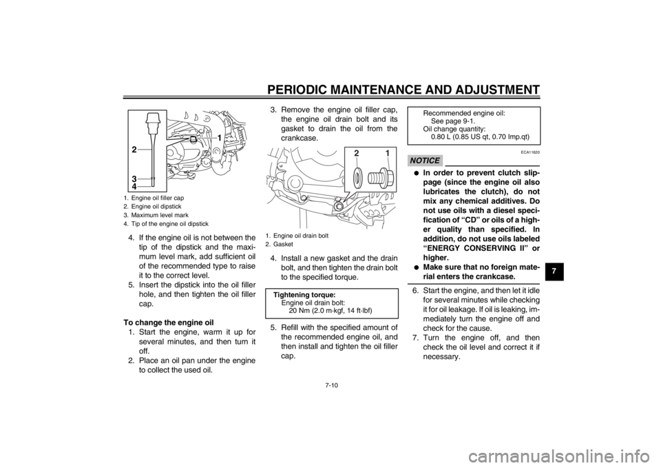
4. If the engine oil is not between the
tip of the dipstick and the maxi-
mum level mark, add sufficient oil
of the recommended type to raise
it to the correct level.
5. Insert the dipstick into the oil filler hole, and then tighten the oil filler
cap.
To change the engine oil 1. Start the engine, warm it up for several minutes, and then turn it
off.
2. Place an oil pan under the engine to collect the used oil. 3. Remove the engine oil filler cap,
the engine oil drain bolt and its
gasket to drain the oil from the
crankcase.
4. Install a new gasket and the drain bolt, and then tighten the drain bolt
to the specified torque.
5. Refill with the specified amount of the recommended engine oil, and
then install and tighten the oil filler
cap.
NOTICE
ECA11620
●
In order to prevent clutch slip-
page (since the engine oil also
lubricates the clutch), do not
mix any chemical additives. Do
not use oils with a diesel speci-
fication of “CD” or oils of a high-
er quality than specified. In
addition, do not use oils labeled
“ENERGY CONSERVING II” or
higher.
●
Make sure that no foreign mate-
rial enters the crankcase.
6. Start the engine, and then let it idlefor several minutes while checking
it for oil leakage. If oil is leaking, im-
mediately turn the engine off and
check for the cause.
7. Turn the engine off, and then check the oil level and correct it if
necessary.
1. Engine oil filler cap
2. Engine oil dipstick
3. Maximum level mark
4. Tip of the engine oil dipstick
1
3
4
2
1. Engine oil drain bolt
2. Gasket
Tightening torque: Engine oil drain bolt:20 Nm (2.0 m·kgf, 14 ft·lbf)
1
2
Recommended engine oil: See page 9-1.
Oil change quantity: 0.80 L (0.85 US qt, 0.70 Imp.qt)
U5B685E0.book Page 10 Tuesday, July 10, 2012 5:06 PM
Page 60 of 88

PERIODIC MAINTENANCE AND ADJUSTMENT
7-17
7very carefully and replace it as
soon as possible with a high-
quality product.
●
Ride conservatively after
changing a tire since the tire
must seat itself on the rim prop-
erly. Failure to allow proper
seating may cause tire failure,
which may result in damage to
the motorcycle and injury to the
rider.
EAU21943
Spoke wheels
WARNING
EWA10610
The wheels on this model are not de-
signed for use with tubeless tires.
Do not attempt to use tubeless tires
on this model.To maximize the performance, durabil-
ity, and safe operation of your motorcy-
cle, note the following points regarding
the specified wheels.●
The wheel rims should be checked
for cracks, bends, warpage or oth-
er damage, and the spokes for
looseness or damage before each
ride. If any damage is found, have
a Yamaha dealer replace the
wheel. Do not attempt even the
smallest repair to the wheel. A de-
formed or cracked wheel must be
replaced.
●
The wheel should be balanced
whenever either the tire or wheel
has been changed or replaced. An
unbalanced wheel can result in
poor performance, adverse han-
dling characteristics, and a short-
ened tire life.
EAU44663
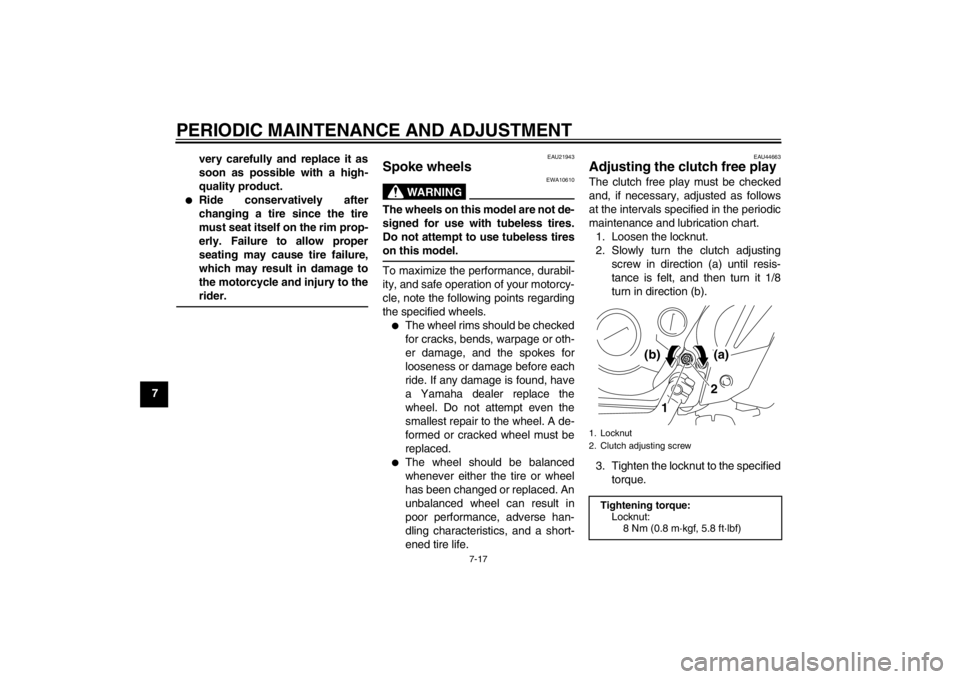
Adjusting the clutch free play The clutch free play must be checked
and, if necessary, adjusted as follows
at the intervals specified in the periodic
maintenance and lubrication chart.
1. Loosen the locknut.
2. Slowly turn the clutch adjusting screw in direction (a) until resis-
tance is felt, and then turn it 1/8
turn in direction (b).
3. Tighten the locknut to the specified torque.1. Locknut
2. Clutch adjusting screwTightening torque:Locknut:
8 Nm (0.8 m·kgf, 5.8 ft·lbf)
1 2
(a)
(b)
U5B685E0.book Page 17 Tuesday, July 10, 2012 5:06 PM
Page 61 of 88

PERIODIC MAINTENANCE AND ADJUSTMENT
7-18
7
TIPWhen tightening the locknut, hold the
clutch adjusting screw with a screwdriv-
er so that it does not turn together with
the locknut.
EAU44884
Adjusting the brake lever free
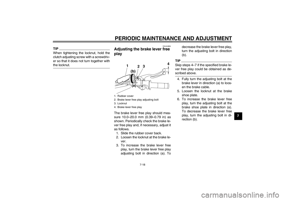
play The brake lever free play should mea-
sure 10.0–20.0 mm (0.39–0.79 in) as
shown. Periodically check the brake le-
ver free play and, if necessary, adjust it
as follows.1. Slide the rubber cover back.
2. Loosen the locknut at the brake le- ver.
3. To increase the brake lever free play, turn the brake lever free play
adjusting bolt in direction (a). To decrease the brake lever free play,
turn the adjusting bolt in direction
(b).
TIPSkip steps 4–7 if the specified brake le-
ver free play could be obtained as de-
scribed above.4. Fully turn the adjusting bolt at the
brake lever in direction (a) to loos-
en the brake cable.
5. Loosen the locknut at the brake shoe plate.
6. To increase the brake lever free play, turn the adjusting bolt at the
brake shoe plate in direction (a).
To decrease the brake lever free
play, turn the adjusting bolt in di-
rection (b).
1. Rubber cover
2. Brake lever free play adjusting bolt
3. Locknut
4. Brake lever free play
3
2
1
(b)
(a) 4
U5B685E0.book Page 18 Tuesday, July 10, 2012 5:06 PM
Page 81 of 88

SPECIFICATIONS
9-1
9
Dimensions:Overall length:1565 mm (61.6 in)
Overall width:
680 mm (26.8 in)
Overall height: 923 mm (36.3 in)
Seat height: 670 mm (26.4 in)
Wheelbase:
1080 mm (42.5 in)
Ground clearance: 180 mm (7.09 in)
Minimum turning radius: 1660 mm (65.4 in)Weight:Curb weight:72 kg (159 lb)
Technical permissible mass (Maximum load +
curb weight): 132 kg (291 lb)Noise and vibration level:Noise level (77/311/EEC):
TT-R110E 78.9 dB(A)
Vibration on seat (EN1032, ISO5008): TT-R110E Will not exceed 0.5 m/s²
Vibration on handlebar (EN1032, ISO5008): TT-R110E Will not exceed 2.5 m/s²Engine:Engine type:Air cooled 4-stroke, SOHC
Cylinder arrangement: Single cylinder Displacement:
110 cm³
Bore × stroke:
51.0 × 54.0 mm (2.01 × 2.13 in)
Compression ratio:
9.30 : 1
Starting system: Electric starter and kickstarter
Lubrication system: Wet sump
Engine oil:Recommended brand:YAMALUBE
Type: SAE 10W-30, 10W-40, 10W-50, 15W-40,
20W-40 or 20W-50
Recommended engine oil grade: API service SG type or higher, JASO
standard MA
Engine oil quantity: Periodic oil change:0.80 L (0.85 US qt, 0.70 Imp.qt)
Air filter:Air filter element:Wet elementFuel:Recommended fuel:TT-R110E Regular unleaded gasoline
(Gasohol (E10) acceptable)
TT-R110ED Regular unleaded gasoline
(Gasohol (E10) acceptable) (CAN)
TT-R110ED Unleaded gasoline (Gasohol
(E10) acceptable) (AUS)
Fuel tank capacity:
3.8 L (1.00 US gal, 0.84 Imp.gal)
Fuel reserve amount: 0.5 L (0.13 US gal, 0.11 Imp.gal)Carburetor:Type × quantity:
VM16 x 1Spark plug(s):Manufacturer/model: NGK/CR6HSA
Spark plug gap:
0.6–0.7 mm (0.024–0.028 in)Clutch:Clutch type:Wet, multiple-disc and centrifugal
automaticTransmission:Primary reduction ratio:
3.722 (67/18)
Final drive: Chain
Secondary reduction ratio: 2.500 (35/14)
–20 –10 0 1020 30 40 50 �C
10 30 50 70 90 110
0 130 �F
SAE 10W-30
SAE 15W-40SAE 20W-40SAE 20W-50
SAE 10W-40SAE 10W-50
U5B685E0.book Page 1 Tuesday, July 10, 2012 5:06 PM