2013 YAMAHA GRIZZLY 700 brake light
[x] Cancel search: brake lightPage 142 of 174

8-51
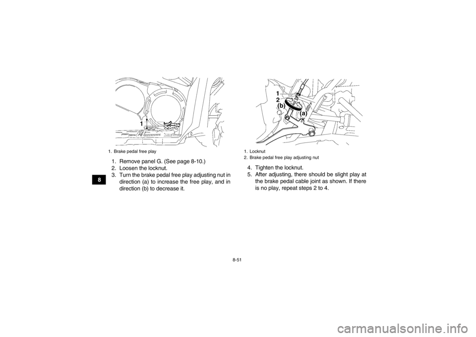
81. Remove panel G. (See page 8-10.)
2. Loosen the locknut.
3. Turn the brake pedal free play adjusting nut in
direction (a) to increase the free play, and in
direction (b) to decrease it. 4. Tighten the locknut.
5. After adjusting, there should be slight play at
the brake pedal cable joint as shown. If there
is no play, repeat steps 2 to 4.
1. Brake pedal free play
1. Locknut
2. Brake pedal free play adjusting nut
U1HP61E0.book Page 51 Thursday, April 5, 2012 3:33 PM
Page 143 of 174

8-52
8
6. Install the panel.
If the correct free play cannot be obtained, have a
Yamaha dealer adjust it.
TIPWhen adjusting the rear brake pedal free play:●Be sure not to step on the brake pedal.●Make sure the rear brake lever and brake pedal
do not move.
EBU24230Axle boots The axle boots must be checked for damage at the
intervals specified in the periodic maintenance and
lubrication chart. Check the axle boots for tears or
damage. If any damage is found, have them re-
placed by a Yamaha dealer.
1. Brake pedal cable joint
2. Slight play (0.1–0.5 mm [0.004–0.02 in])
1
2
1. Front axle boot (each side)
1
1
U1HP61E0.book Page 52 Thursday, April 5, 2012 3:33 PM
Page 154 of 174
![YAMAHA GRIZZLY 700 2013 Owners Manual 8-63
86. Connect the headlight coupler.
7. Install the headlight bulb cover.
NOTICE:
Make sure the headlight bulb cover is se-
curely fitted and seated properly.
[ECB01080]
8. Install the cover at t YAMAHA GRIZZLY 700 2013 Owners Manual 8-63
86. Connect the headlight coupler.
7. Install the headlight bulb cover.
NOTICE:
Make sure the headlight bulb cover is se-
curely fitted and seated properly.
[ECB01080]
8. Install the cover at t](/manual-img/51/50464/w960_50464-153.png)
8-63
86. Connect the headlight coupler.
7. Install the headlight bulb cover.
NOTICE:
Make sure the headlight bulb cover is se-
curely fitted and seated properly.
[ECB01080]
8. Install the cover at the rear of the headlight.
9. Adjust the headlight beam if necessary.EBU25551Adjusting a headlight beam NOTICEECB00690It is advisable to have a Yamaha dealer make
this adjustment.
To raise a headlight beam, turn the headlight beam
adjusting screw in direction (a).
To lower a headlight beam, turn the adjusting
screw in direction (b).EBU25642Replacing the tail/brake light bulb If the tail/brake light bulb burns out, replace it as
follows. 1. Remove panel H. (See page 8-10.)
2. Remove the tail/brake light bulb holder (to- gether with the bulb) by turning it counter-
clockwise.
1. Do not touch the glass part of the bulb.
1. Headlight beam adjusting screw
U1HP61E0.book Page 63 Thursday, April 5, 2012 3:33 PM
Page 155 of 174

8-64
8
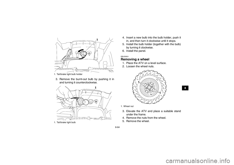
3. Remove the burnt-out bulb by pushing it in
and turning it counterclockwise. 4. Insert a new bulb into the bulb holder, push it
in, and then turn it clockwise until it stops.
5. Install the bulb holder (together with the bulb) by turning it clockwise.
6. Install the panel.
EBU25651Removing a wheel 1. Place the ATV on a level surface.
2. Loosen the wheel nuts.
3. Elevate the ATV and place a suitable stand under the frame.
4. Remove the nuts from the wheel.
5. Remove the wheel.
1. Tail/brake light bulb holder
1. Tail/brake light bulb
1. Wheel nut
U1HP61E0.book Page 64 Thursday, April 5, 2012 3:33 PM
Page 167 of 174

10-5
10
Wheel travel:230 mm (9.1 in)Electrical system:Ignition system:
TCI
Charging system: AC magnetoBattery:Model:
YTX20L-BS
Voltage, capacity: 12 V, 18.0 AhHeadlight:Bulb type:
Halogen bulbBulb voltage, wattage × quantity:Headlight:
12 V, 35.0/35.0 W × 2
Tail/brake light:
12 V, 5.0/21.0 W × 1
Meter lighting: EL (Electroluminescent)
Neutral indicator light: LED
Reverse indicator light:
LED
Coolant temperature warning light: LED
Engine trouble warning light: LED EPS warning light:
YFM700FAPD LED
YFM700FAPSED LED
YFM7FGPAD LED
YFM7FGPD LED
YFM7FGPHD LED
YFM7FGPLED LED
YFM7FGPSED LED
Park indicator light: LED
On-Command four-wheel-drive/differential gear lock
indicator: LCD
High-range indicator light:
LED
Low-range indicator light: LED
Differential gear lock indicator light: LED
Fuses:Main fuse:40.0 A
Fuel injection system fuse: 15.0 A
EPS fuse:
YFM700FAPD 40.0 A
YFM700FAPSED 40.0 A
YFM7FGPAD 40.0 A
YFM7FGPD 40.0 A
YFM7FGPHD 40.0 A
YFM7FGPLED 40.0 A
YFM7FGPSED 40.0 A
U1HP61E0.book Page 5 Thursday, April 5, 2012 3:33 PM
Page 171 of 174

INDEX
AAccessories and loading ................................................ 6-6
Accessories, auxiliary jack ........................................... 4-23
Air filter element, cleaning ............................................ 8-39
Axle boots .................................................................... 8-52BBattery .......................................................................... 8-56
Brake fluid, changing ................................................... 8-49
Brake fluid level, checking ........................................... 8-48
Brake lever, front .......................................................... 4-14
Brake levers, checking and lubricating ........................ 8-53
Brake pads, checking the front and rear ...................... 8-47
Brake pedal and rear brake lever ................................. 4-14
Brake pedal, checking and lubricating ......................... 8-54
Brake pedal free play, adjusting ................................... 8-50
Brakes .......................................................................... 8-46
Brakes, front and rear .................................................... 5-3CCables, checking and lubricating ................................. 8-53
Carrier, front ................................................................. 4-21
Carrier, rear .................................................................. 4-21
Chassis fasteners .......................................................... 5-7
Cleaning ......................................................................... 9-1
Coolant .................................................................. 5-3, 8-32
Coolant temperature warning light ................................. 4-3DDifferential gear oil ................................................ 5-3, 8-29
Drive select lever ......................................................... 4-15 Drive select lever and driving in reverse ........................ 6-2
Drive select lever safety system cable, adjusting ........ 8-46
EEngine break-in .............................................................. 6-4
Engine oil ....................................................................... 5-3
Engine oil and oil filter cartridge ................................... 8-22
Engine stop switch ......................................................... 4-7
Engine trouble warning light .......................................... 4-3
EPS warning light (for EPS model) ................................ 4-3FFinal gear oil ......................................................... 5-3, 8-27
Four-wheel-drive/differential gear lock indicator ............ 4-4
Front and rear brake lever free play, checking ............ 8-49
Fuel ....................................................................... 4-16, 5-3
Fuel tank cap ............................................................... 4-15
Fuses, replacing .......................................................... 8-59HHandlebar switches ....................................................... 4-7
Headlight beam, adjusting ........................................... 8-63
Headlight bulb, replacing ............................................. 8-61
High-range indicator light ............................................... 4-2
Horn switch .................................................................... 4-8IIdentification numbers .................................................. 11-1
Indicator lights and warning lights .................................. 4-2
Instruments, lights and switches .................................... 5-7LLabel locations ............................................................... 1-1
U1HP61E0.book Page 1 Thursday, April 5, 2012 3:33 PM
Page 172 of 174

Light switch .................................................................... 4-8
Low-range indicator light ................................................ 4-2MMain switch .................................................................... 4-1
Maintenance and lubrication chart ................................. 8-5
Maintenance chart, emission control system ................. 8-3
Model label ................................................................... 11-1
Multi-function display ...................................................... 4-5NNeutral indicator light ..................................................... 4-2OOn-Command differential gear lock switch .................. 4-10
On-Command four-wheel-drive switch ........................... 4-9
Override switch .............................................................. 4-8
Owner’s manual and tool kit ........................................... 8-2PPanels, removing and installing ................................... 8-10
Park indicator light .......................................................... 4-2
Parking ........................................................................... 6-5
Parking on a slope ......................................................... 6-5
Part locations ................................................................. 3-1RRadiator grills, removing .............................................. 8-20
Rear knuckle pivots, lubricating ................................... 8-55
Reverse indicator light .................................................... 4-2
Riding your ATV ............................................................. 7-1SSafety information .......................................................... 2-1
Seat .............................................................................. 4-18
Shock absorber assemblies, adjusting the front and rear ........................................ 4-21
Spark arrester, cleaning ............................................... 8-43 Spark plug, checking .................................................... 8-20
Specifications ............................................................... 10-1
Speed limiter ................................................................ 4-13
Stabilizer bushes, checking .......................................... 8-55
Starting the engine ......................................................... 6-1
Start switch ..................................................................... 4-8
Steering shaft, lubricating ............................................. 8-56
Storage ........................................................................... 9-2
Storage compartments ................................................. 4-18
TTail/brake light bulb, replacing ..................................... 8-63
Throttle lever ......................................................... 4-13, 5-4
Throttle lever free play, adjusting ................................. 8-45
Tires ............................................................................... 5-4
Troubleshooting ........................................................... 8-66
Troubleshooting charts ................................................. 8-67VValve clearance ............................................................ 8-46
V-belt case drain plug .................................................. 8-45
Vehicle identification number ....................................... 11-1WWheel hub bearings, checking ..................................... 8-55
Wheel, installing ........................................................... 8-65
Wheel, removing .......................................................... 8-64
U1HP61E0.book Page 2 Thursday, April 5, 2012 3:33 PM