2013 YAMAHA FZ8 N clock
[x] Cancel search: clockPage 25 of 110

INSTRUMENT AND CONTROL FUNCTIONS
3-8
3
EAU46767
Multi-function meter unit
WARNING
EWA12423
Be sure to stop the vehicle before
makin g any settin g chan ges to the
multi-function meter unit. Chang ing
settin gs while ri din g can distract the
operator an d increase the risk of an
acci dent.
The multi-function meter unit is
equipped with the following:
a speedometer
a tachometer
an odometer
two tripmeters (which show the
distance traveled since they were
last set to zero)
a fuel reserve tripmeter (which
shows the distance traveled since
the left segment of the fuel meter
started flashing)
a clock
a fuel meter
a coolant temperature display
a self-diagnosis deviceTIPBe sure to turn the key to “ON” be-
fore using the “SELECT” and “RE-
SET” buttons.
For the UK only: To switch the
speedometer and odometer/trip-
meter displays between kilome-
ters and miles, press the
“SELECT” button for at least one
second.
Speed ometer
The speedometer shows the vehicle’s
traveling speed.
Tachometer
The electric tachometer allows the rid-
er to monitor the engine speed and
keep it within the ideal power range.
When the key is turned to “ON”, the ta-
chometer needle will sweep once
across the r/min range and then return
to zero r/min in order to test the electri-
cal circuit.NOTICE
ECA10032
Do not operate the en gine in the ta-
chometer red zone.
1. Fuel meter
2. Coolant temperature display
3. Speedometer
4. Tachometer
5. Odometer/tripmeter/fuel reserve tripmeter
6. “SELECT” button
7. “RESET” button
8. Clock
ABS
1
2
3
4
87 6 5
1. Tachometer
2. Tachometer red zone
ABS1
2
U2SHE1E0.book Page 8 Tuesday, July 15, 2014 4:04 PM
Page 26 of 110

INSTRUMENT AND CONTROL FUNCTIONS
3-9
3Re
d zone: 11500 r/min an d a bove
Clock
The clock displays when the key is
turned to “ON”. In addition, the clock
can be displayed for 10 seconds by
pushing the “SELECT” button when
the main switch is in the “OFF”,
“LOCK” or “ ” position.
To set the clock1. Turn the key to “ON”.
2. Push the “SELECT” button and
“RESET” button together for at
least two seconds.
3. When the hour digits start flash- ing, push the “RESET” button to
set the hours. 4. Push the “SELECT” button, and
the minute digits will start flashing.
5. Push the “RESET” button to set the minutes.
6. Push the “SELECT” button and then release it to start the clock.
O dometer an d tripmeter mo des
Push the “SELECT” button to switch
the display between the odometer
mode “ODO” and the tripmeter modes
“TRIP A” and “TRIP B” in the following
order:
TRIP A → TRIP B → ODO → TRIP A
When the fuel amount in the fuel tank
decreases to 3.4 L (0.90 US gal,
0.75 Imp.gal), the left segment of the
fuel meter will start flashing, and the odometer display will automatically
change to the fuel reserve tripmeter
mode “F-TRIP” and start counting the
distance traveled from that point. In
that case, push the “SELECT” button
to switch the display between the vari-
ous tripmeter and odometer modes in
the following order:
F-TRIP
→ TRIP A → TRIP B → ODO →
F-TRIP
To reset a tripmeter, select it by push-
ing the “SELECT” button, and then
push the “RESET” button for at least
one second. If you do not reset the fuel
reserve tripmeter manually, it will reset
itself automatically and the display will
return to the prior mode after refueling
and traveling 5 km (3 mi).1. Clock1
1. Odometer/tripmeter/fuel reserve tripmeter
1
U2SHE1E0.book Page 9 Tuesday, July 15, 2014 4:04 PM
Page 32 of 110

INSTRUMENT AND CONTROL FUNCTIONS
3-15
3wheel hu
bs may b e damag ed , re-
sultin g in improper performance of
the ABS system.
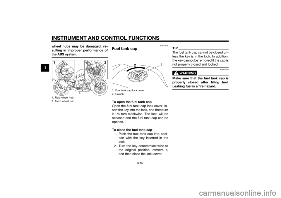
EAU13075
Fuel tank capTo open the fuel tank cap
Open the fuel tank cap lock cover, in-
sert the key into the lock, and then turn
it 1/4 turn clockwise. The lock will be
released and the fuel tank cap can be
opened.
To close the fuel tank cap 1. Push the fuel tank cap into posi- tion with the key inserted in the
lock.
2. Turn the key counterclockwise to the original position, remove it,
and then close the lock cover.
TIPThe fuel tank cap cannot be closed un-
less the key is in the lock. In addition,
the key cannot be removed if the cap is
not properly closed and locked.
WARNING
EWA11092
Make sure that the fuel tank cap is
properly close d after fillin g fuel.
Leakin g fuel is a fire hazar d.
1. Rear wheel hub
2. Front wheel hub1
2
1. Fuel tank cap lock cover
2. Unlock.
2 1
U2SHE1E0.book Page 15 Tuesday, July 15, 2014 4:04 PM
Page 35 of 110

INSTRUMENT AND CONTROL FUNCTIONS
3-18
3
NOTICE
ECA10702
Use only unleaded g asoline. The use
of lead ed g asoline will cause unre-
paira ble damag e to the catalytic
converter.
EAU49644
SeatsPassen ger seat
To remove the passenger seat1. Insert the key into the seat lock, and then turn it counterclockwise.
2. While holding the key in that posi- tion, lift the rear of the passenger
seat and pull it off. To install the passenger seat
1. Insert the projections on the front
of the passenger seat into the seat
holders as shown, and then push
the rear of the seat down to lock it
in place.
2. Remove the key.
Ri der seat
To remove the rider seatPull back the rear of the rider seat as
shown, remove the bolts, and then pull
the seat off.
1. Seat lock
2. Unlock.
1
2
1. Projection
2. Seat holder
12
U2SHE1E0.book Page 18 Tuesday, July 15, 2014 4:04 PM
Page 83 of 110

PERIODIC MAINTENANCE AND ADJUSTMENT
6-33
6
FZ8-NA FZ8-N FZ8-NA
1. Fuse box
2. Fuel injection system fuse
3. Fuel injection system spare fuse
4. Main fuse
4
1
2
3
1. Ignition fuse
2. Signaling system fuse
3. Taillight fuse
4. Backup fuse (for clock and immobilizer sys-
tem)
5. Right radiator fan motor fuse
6. Left radiator fan motor fuse
7. Headlight fuse
8. Spare fuse
18
7
2
3
4
5
6
1. Ignition fuse
2. Signaling system fuse
3. Headlight fuse
4. Backup fuse (for clock and immobilizer sys- tem)
5. ABS solenoid fuse
6. ABS motor fuse
7. Spare fuse
8. ABS control unit fuse
9. Right radiator fan motor fuse
1
8
92
3
4
5
6
7
7
U2SHE1E0.book Page 33 Tuesday, July 15, 2014 4:04 PM
Page 87 of 110

PERIODIC MAINTENANCE AND ADJUSTMENT
6-37
6
13. Have a Yamaha dealer adjust the
headlight beam if necessary.
EAU50771
Replacin g the auxiliary li ght
b ul bIf the auxiliary light bulb burns out, re-
place it as follows.
1. Remove the headlight unit. (See page 6-35.)
2. Remove the auxiliary light coupler (together with the socket and
bulb) by turning the coupler coun-
terclockwise.
3. Remove the burnt-out bulb by pulling it out. 4. Insert a new bulb into the socket.
5. Install the coupler (together with
the socket and bulb) by turning it
clockwise.
6. Install the headlight unit.1. Auxiliary light coupler
1
1. Auxiliary light bulb
2. Auxiliary light bulb socket
3. Auxiliary light coupler
1
2
3
U2SHE1E0.book Page 37 Tuesday, July 15, 2014 4:04 PM
Page 88 of 110

PERIODIC MAINTENANCE AND ADJUSTMENT
6-38
6
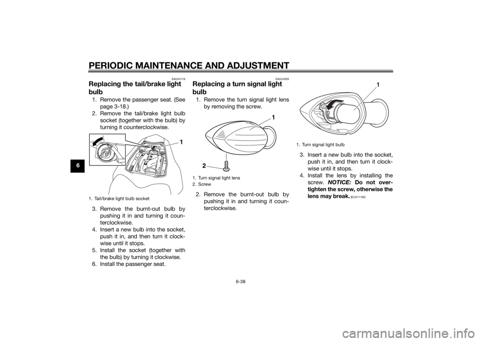
EAU24116
Replacing the tail/ brake li ght
b ul b1. Remove the passenger seat. (See
page 3-18.)
2. Remove the tail/brake light bulb socket (together with the bulb) by
turning it counterclockwise.
3. Remove the burnt-out bulb by pushing it in and turning it coun-
terclockwise.
4. Insert a new bulb into the socket, push it in, and then turn it clock-
wise until it stops.
5. Install the socket (together with the bulb) by turning it clockwise.
6. Install the passenger seat.
EAU24205
Replacin g a turn si gnal li ght
b ul b1. Remove the turn signal light lens
by removing the screw.
2. Remove the burnt-out bulb by pushing it in and turning it coun-
terclockwise. 3. Insert a new bulb into the socket,
push it in, and then turn it clock-
wise until it stops.
4. Install the lens by installing the screw. NOTICE: Do not over-
ti g hten the screw, otherwise the
lens may break.
[ECA11192]
1. Tail/brake light bulb socket
1
1. Turn signal light lens
2. Screw
1
2
1. Turn signal light bulb
1
U2SHE1E0.book Page 38 Tuesday, July 15, 2014 4:04 PM
Page 96 of 110

PERIODIC MAINTENANCE AND ADJUSTMENT
6-46
6En
gine overheatin g
WARNING
EWA10401
Do not remove the ra diator cap when the en gine an d ra diator are hot. Scal din g hot flui d an d steam may be
b lown out un der pressure, which coul d cause serious injury. Be sure to wait until the en gine has coole d.
After removin g the ra diator cap retainin g b olt, place a thick ra g, like a towel, over the rad iator cap, and then
slowly rotate the cap counterclockwise to the d etent to allow any residual pressure to escape. When the hiss-
in g soun d has stoppe d, press d own on the cap while turnin g it counterclockwise, an d then remove the cap.TIPIf coolant is not available, tap water can be temporarily used instead, provided that it is changed to the recommended cool-
ant as soon as possible.
Wait until the
engine has cooled.
Check the coolant level in the
reservoir and radiator.
The coolant level
is OK.The coolant level is low.
Check the cooling system
for leakage.
Have a Yamaha dealer checkand repair the cooling system.Add coolant. (See TIP.)
Start the engine. If the engine overheats again,
have a
Yamaha dealer check
and repair the cooling system.
There is
leakage.
There is
no leakage.
U2SHE1E0.book Page 46 Tuesday, July 15, 2014 4:04 PM