2013 YAMAHA FX HO fuel
[x] Cancel search: fuelPage 49 of 116

Instrument operation
43
TIP:
The hour meter is selected at the Yamaha
factory.
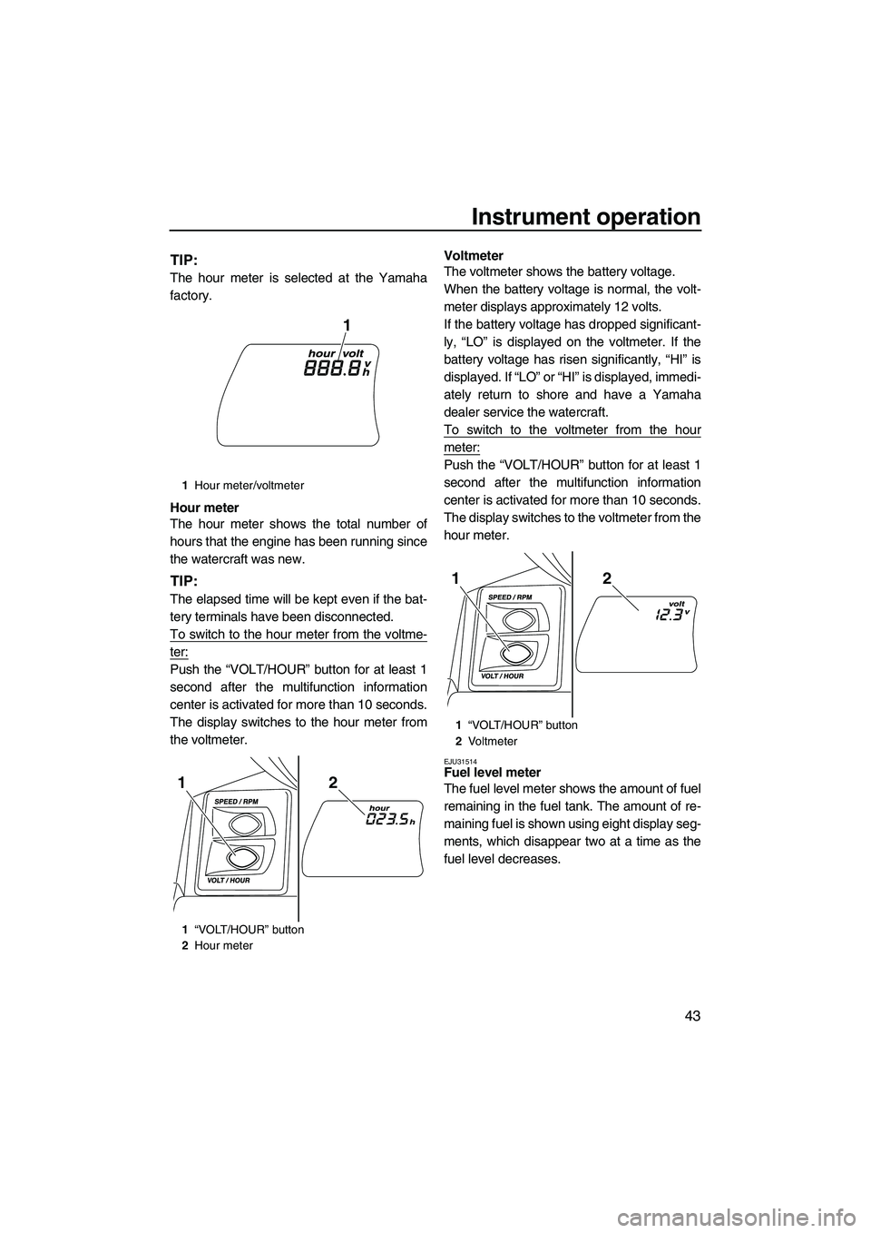
Hour meter
The hour meter shows the total number of
hours that the engine has been running since
the watercraft was new.
TIP:
The elapsed time will be kept even if the bat-
tery terminals have been disconnected.
To switch to the hour meter from the voltme-
ter:
Push the “VOLT/HOUR” button for at least 1
second after the multifunction information
center is activated for more than 10 seconds.
The display switches to the hour meter from
the voltmeter.Voltmeter
The voltmeter shows the battery voltage.
When the battery voltage is normal, the volt-
meter displays approximately 12 volts.
If the battery voltage has dropped significant-
ly, “LO” is displayed on the voltmeter. If the
battery voltage has risen significantly, “HI” is
displayed. If “LO” or “HI” is displayed, immedi-
ately return to shore and have a Yamaha
dealer service the watercraft.
To switch to the voltmeter from the hour
meter:
Push the “VOLT/HOUR” button for at least 1
second after the multifunction information
center is activated for more than 10 seconds.
The display switches to the voltmeter from the
hour meter.
EJU31514Fuel level meter
The fuel level meter shows the amount of fuel
remaining in the fuel tank. The amount of re-
maining fuel is shown using eight display seg-
ments, which disappear two at a time as the
fuel level decreases.
1
Hour meter/voltmeter
1 “VOLT/HOUR” button
2 Hour meter
1
21
1“VOLT/HOUR” button
2 Vo l t m e t e r
21
UF2S71E0.book Page 43 Tuesday, August 21, 2012 2:33 PM
Page 50 of 116

Instrument operation
44
TIP:
The accuracy of the fuel level meter varies de-
pending on the operating conditions. Use this
function as a reference only.
EJU42340Fuel level warning
If the fuel remaining in the fuel tank drops to
about 18 L (4.8 US gal, 4.0 Imp. gal), the low-
est two fuel level segments, the fuel indicator,
and the “WARNING” indicator light blink, and
the buzzer sounds intermittently.
If the fuel level warning is activated, refill the
fuel tank as soon as possible. (See page 58
for information on filling the fuel tank.)
After the fuel tank is refilled, the warning sig-
nals will be cleared when the engine is restart-
ed.
TIP:
Push any of the operation buttons for the mul-
tifunction information center to stop the buzz-
er.
EJU42270Oil pressure warning
If the oil pressure drops significantly, the oil
pressure warning indicator and the “WARN-
ING” indicator light blink, and the buzzer
sounds intermittently. At the same time, the
engine speed is limited.
If the oil pressure warning is activated, imme-
diately reduce the engine speed, return to
shore, and then check the engine oil level.
(See page 60 for information on checking the
engine oil level.) If the oil level is sufficient,
have a Yamaha dealer check the watercraft.
TIP:
Push any of the operation buttons for the mul-
tifunction information center to stop the buzz-
er.
EJU42370Engine overheat warning
If the engine temperature rises significantly,
the engine overheat warning indicator and the
“WARNING” indicator light blink, and the
buzzer sounds intermittently. Then, the en-
gine overheat warning indicator and the
“WARNING” indicator light stop blinking and
remain on, and the buzzer sounds continu-
1Fuel level meter
1
UF2S71E0.book Page 44 Tuesday, August 21, 2012 2:33 PM
Page 53 of 116

Instrument operation
47
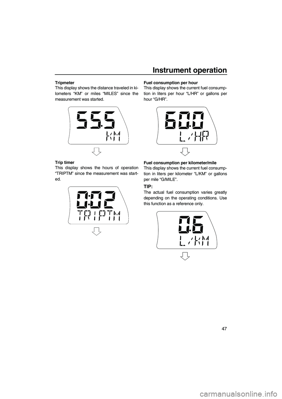
Tripmeter
This display shows the distance traveled in ki-
lometers “KM” or miles “MILES” since the
measurement was started.
Trip timer
This display shows the hours of operation
“TRIPTM” since the measurement was start-
ed.Fuel consumption per hour
This display shows the current fuel consump-
tion in liters per hour “L/HR” or gallons per
hour “G/HR”.
Fuel consumption per kilometer/mile
This display shows the current fuel consump-
tion in liters per kilometer “L/KM” or gallons
per mile “G/MILE”.
TIP:
The actual fuel consumption varies greatly
depending on the operating conditions. Use
this function as a reference only.
UF2S71E0.book Page 47 Tuesday, August 21, 2012 2:33 PM
Page 64 of 116

Operation and handling requirements
58
EJU31822
Fuel requirements EJU42400Fuel
WARNING
EWJ00282
●Gasoline and gasoline vapors are ex-
tremely flammable. To avoid fires and
explosions and to reduce the risk of in-
jury when refueling, follow these in-
structions.
●Gasoline is poisonous and can cause in-
jury or death. Handle gasoline with care.
Never siphon gasoline by mouth. If you
should swallow some gasoline, inhale a
lot of gasoline vapor, or get some gaso-
line in your eyes, see your doctor imme-
diately. If gasoline spills on your skin,
wash with soap and water. If gasoline
spills on your clothing, change your
clothes.
NOTICE
ECJ00321
●Do not use leaded gasoline. Leaded gas-
oline can seriously damage the engine.
●Avoid getting water and contaminants in
the fuel tank. Contaminated fuel can
cause poor performance and engine
damage. Use only fresh gasoline that
has been stored in clean containers.
Gasohol
There are two types of gasohol: gasohol con-
taining ethanol and that containing methanol.
Gasohol containing ethanol can be used if
ethanol content does not exceed 10% and thefuel meets the minimum octane ratings. E-85
is a fuel blend containing 85% ethanol and
therefore must not be used in this watercraft.
All ethanol blends containing more than 10%
ethanol can cause fuel system damage or en-
gine performance problems.
Yamaha does not recommend gasohol con- taining methanol because it can cause fuel
system damage and engine performance
problems.
To fill the fuel tank:
(1) Before refueling, stop the engine. Do not stand or sit on the watercraft. Never refu-
el while smoking, or while in the vicinity of
sparks, open flames, or other sources of
ignition.
(2) Place the watercraft in a well-ventilated area and in a horizontal position.
(3) Remove the seats, and then check the fuel level. (See page 49 for seat removal
and installation procedures.)
(4) Pull the hood latch rearward, and then lift up the rear of the hood.
Recommended fuel: Regular unleaded gasoline with a
minimum octane rating of86
(Pump octane number) = (R + M)/2
90 (Research octane number)
1Hood latch
1
UF2S71E0.book Page 58 Tuesday, August 21, 2012 2:33 PM
Page 65 of 116

Operation and handling requirements
59
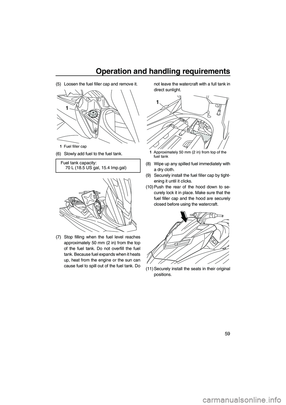
(5) Loosen the fuel filler cap and remove it.
(6) Slowly add fuel to the fuel tank.
(7) Stop filling when the fuel level reachesapproximately 50 mm (2 in) from the top
of the fuel tank. Do not overfill the fuel
tank. Because fuel expands when it heats
up, heat from the engine or the sun can
cause fuel to spill out of the fuel tank. Do not leave the watercraft with a full tank in
direct sunlight.
(8) Wipe up any spilled fuel immediately with a dry cloth.
(9) Securely install the fuel filler cap by tight- ening it until it clicks.
(10) Push the rear of the hood down to se- curely lock it in place. Make sure that the
fuel filler cap and the hood are securely
closed before using the watercraft.
(11) Securely install the seats in their original positions.
1Fuel filler cap
Fuel tank capacity:
70 L (18.5 US gal, 15.4 Imp.gal)
1
1Approximately 50 mm (2 in) from top of the
fuel tank
1
UF2S71E0.book Page 59 Tuesday, August 21, 2012 2:33 PM
Page 71 of 116

Pre-operation checks
65
EJU31981
WARNING
EWJ00411
Failure to inspect or maintain the watercraft properly increases the possibility of an ac-
cident or damage to the watercraft. Do not operate the watercraft if you find any prob-
lem. If a problem cannot be corrected by the procedures provided in this manual, have
the watercraft inspected by a Yamaha dealer.
EJU41232Pre-operation checklist
Before using this watercraft, be sure to perform the checks in the following checklist.
ITEM ROUTINEPAGE
PRE-LAUNCH CHECKS
Engine compartment Ventilate the engine compartment.
Check inside the engine compartment for damage.
67
Fuel system Check the fuel system for leakage.
Check the fuel level in the fuel tank.
67
Water separator Check the water separator for water. 67
Engine unit Check the exterior of the engine unit for damage. 68
Engine oil level Check the engine oil level. 68
Bilge water Check the engine compartment for bilge water. 68
Battery Check the battery connections and electrolyte level. 68
Steering system Check the steering system for proper operation. 69
Adjustable tilt steering sys-
tem Check the adjustable tilt steering system for proper
operation and check that the handlebars are secure-
ly locked in place.
70
Q.S.T.S. Check the Q.S.T.S. for proper operation and check
that the Q.S.T.S. selector is securely locked in place.
70
Shift system Check the shift system for proper operation. 71
Throttle lever Check the throttle lever for proper operation. 71
Remote control transmitter Check the remote control transmitter for proper op-
eration.
72
Engine shut-off cord (lan-
yard) Check the engine shut-off cord (lanyard) for dam-
age.
72
Switches Check the start switch, engine stop switch, and en-
gine shut-off switch for proper operation.
72
Storage compartments Check the storage compartments for damage and
water.
72
Fire extinguisher holder,
cover, and band Check the fire extinguisher holder, cover, and band
for damage.
73
Fire extinguisher Check the condition of the fire extinguisher. 73
Safety equipment Check that safety equipment meeting the applicable
regulations is on board.
73
Hull and deck Check the hull and deck for damage. 73
UF2S71E0.book Page 65 Tuesday, August 21, 2012 2:33 PM
Page 73 of 116

Pre-operation checks
67
EJU32281
Pre-operation check points EJU42380Pre-launch checks
Perform the pre-launch checks in the pre-op-
eration checklist while the watercraft is on
land.
To perform the pre-launch checks:
(1) Remove the seats and removable water-tight storage compartment. (See page 49
for seat removal and installation proce-
dures and page 55 for information on the
removable watertight storage compart-
ment.)
(2) Perform the checks and make sure that there are no malfunctioning items or oth-
er problems.
(3) After completing these checks, securely install the removable watertight storage
compartment and seats in their original
positions.
EJU32333Engine compartment check
WARNING
EWJ00461
Failure to ventilate the engine compart-
ment could result in a fire or explosion. Do
not start the engine if there is a fuel leak.
Ventilate the engine compartment. Leave the
engine compartment open for a few minutes
to allow any fuel vapors to escape. Make sure that there is no damage inside the
engine compartment.
EJU34214Fuel system checks
WARNING
EWJ00381
Leaking fuel can result in fire or explosion.
●Check for fuel leakage regularly.
●If any fuel leakage is found, the fuel sys-
tem must be repaired by a qualified me-
chanic. Improper repairs can make the
watercraft unsafe to operate.
Make sure that there is no damage, leakage,
or other problem in the fuel system.
Check:
●Fuel filler cap and seal for damage
●Fuel tank for damage and leakage
●Fuel hoses and joints for damage and leak-
age
●Fuel tank breather hose for damage and
leakage
EJU36874Fuel level check
Check the fuel level in the fuel tank.
Add fuel if necessary. (See page 58 for infor-
mation on filling the fuel tank.)
EJU32423Water separator check
Make sure that no water has collected in the
water separator. If water has collected in the
UF2S71E0.book Page 67 Tuesday, August 21, 2012 2:33 PM
Page 94 of 116

Care and storage
88
EJU37145
Post-operation care
WARNING
EWJ00330
Always place the watercraft upright in a
horizontal position when storing it, other-
wise fuel could leak out into the engine or
engine compartment, which could create a
fire hazard.
After using the watercraft, always take it out of
the water, clean it, and store it. Leaving the
watercraft in the water for extended periods
will accelerate the rate of normal deterioration
of the jet pump and hull. Marine organisms
and corrosion are some of the conditions that
can shorten the life of many watercraft com-
ponents.
EJU42220Flushing the cooling water passages
NOTICE
ECJ01310
Do not run the engine over 4000 r/min on
land. Also, do not run the engine for more
than 15 seconds without supplying water,
otherwise the engine could overheat.
Flush the cooling water passages to prevent
them from clogging with salt, sand, or dirt.
(1) Place the watercraft in a horizontal posi-tion.
(2) Remove the seats and removable water- tight storage compartment. (See page 49
for seat removal and installation proce-
dures and page 55 for information on the
removable watertight storage compart-
ment.)
(3) Open the stern storage compartment. (See page 54 for information on the stern
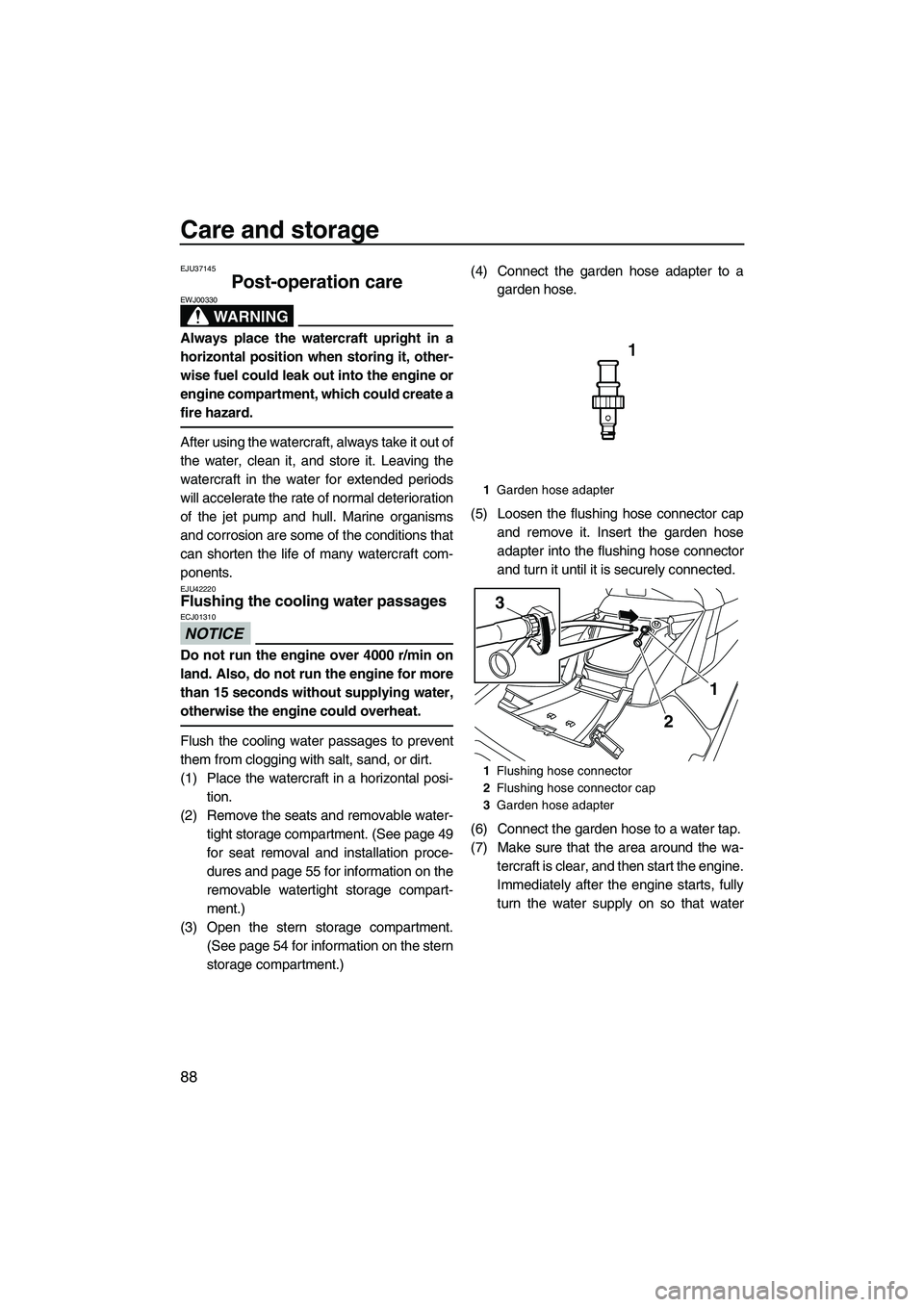
storage compartment.) (4) Connect the garden hose adapter to a
garden hose.
(5) Loosen the flushing hose connector cap and remove it. Insert the garden hose
adapter into the flushing hose connector
and turn it until it is securely connected.
(6) Connect the garden hose to a water tap.
(7) Make sure that the area around the wa- tercraft is clear, and then start the engine.
Immediately after the engine starts, fully
turn the water supply on so that water
1Garden hose adapter
1 Flushing hose connector
2 Flushing hose connector cap
3 Garden hose adapter
1
3
2
UF2S71E0.book Page 88 Tuesday, August 21, 2012 2:33 PM