Page 224 of 422

05 Comfort and driving pleasure
Fuel-driven engine block heater and passenger compartment heater*
05
222* Option/accessory, for more information, see Introduction.
A display text clears automatically after a time
or after one press on the indicator stalk OK
button.
Direct start and immediate stop
1.
Scroll with the thumbwheel to Direct start
Park heat.
2.
Press RESET to select between
ON andOFF.
ON: Parking heater switched on manually or
with programmed timer.
OFF: Parking heater switched off.
Following the direct start of the heater it will be
activated for 50 minutes.
Heating of the passenger compartment will
begin as soon as the engine coolant has
reached the correct temperature.
NOTE
The car can be started and driven while the
parking heater is running.
Setting the timer
The time when the car shall be used and heated
is specified with the timer.
Select between
TIMER 1 and TIMER 2.
NOTE
The timer can only be programmed when
the remote control key is in key position I,
see page 78 - programming must therefore
be carried out before starting the engine.
1.
Scroll with the thumbwheel to Park heat
timer 1.
2.
Briefly press RESET to move to the flash-
ing hours setting.
3. Select the required hour using the thumb-
wheel.
4.
Briefly press RESET to move to the flash-
ing minutes setting.
5. Select the required minute using the
thumbwheel.
6.
Briefly press RESET to confirm the setting.
7.
Press RESET to activate the timer.
After setting
Park heat timer 1 a second start
time can be programmed with Park heat timer
2 by scrolling to it with the thumbwheel.Set the alternative time in the same way as
Park heat timer 1.
Deactivating a timer-started heaterA timer-started heater can be switched off
manually before the set time has elapsed. Pro-
ceed as follows:
1.
Press OK.
2. Use the thumbwheel to scroll to the text
Park heat timer 1 or 2.
>
The text
ON flashes on the display.
3.
Press RESET.
>
The text
OFF is shown with a constant
glow and the heater is switched OFF.
A timer-started heater can be switched off in
accordance with the instructions in the section
"Direct start and immediate stop", see
page 222.
Clock/timerThe heater's time is connected to the car's
clock.
NOTE
All timer programming will be cleared if the
car's clock is reset.
ProCarManuals.com
Page 303 of 422
07 During your journey
Driving with a trailer
07
��
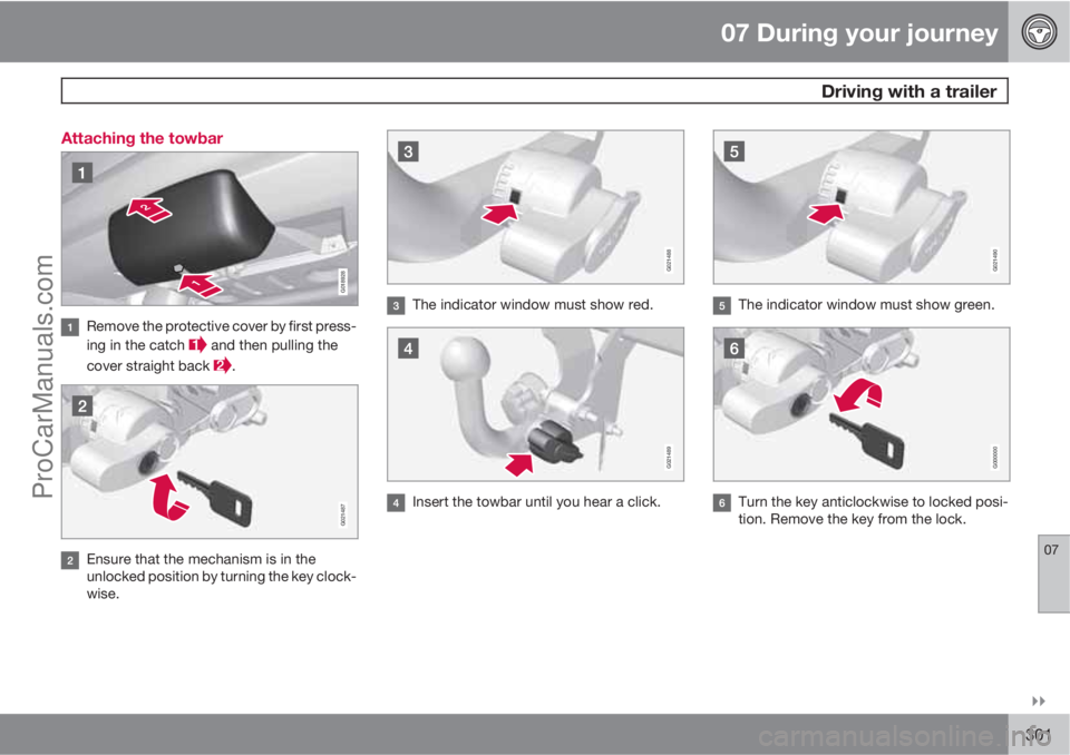
301 Attaching the towbar
G018928
Remove the protective cover by first press-
ing in the catch
and then pulling the
cover straight back
.
G021487
Ensure that the mechanism is in the
unlocked position by turning the key clock-
wise.
G021488
The indicator window must show red.
G021489
Insert the towbar until you hear a click.
G021490
The indicator window must show green.
G000000
Turn the key anticlockwise to locked posi-
tion. Remove the key from the lock.
ProCarManuals.com
Page 304 of 422
07 During your journey
Driving with a trailer
07
302
G021494
Check that the towbar is secure by pulling
it up, down and back.
WARNING
If the towbar is not fitted correctly then it
must be detached and reattached in
accordance with the previous instructions.
IMPORTANT
Only grease in the ball for the towing hitch,
the remainder of the towbar should be clean
and dry.
G021495
Safety cable.
WARNING
Be sure to attach the trailer's safety cable to
the correct place.
Removing the towbar
Insert the key and turn it clockwise to the
unlocked position.
Push in the locking wheel and turn it
anticlockwise
until you hear a click.
Turn the locking wheel down fully, until it
comes to a stop. Hold it in this position
while pulling the towbar rearward and
upward.
WARNING
Secure the towbar safely if it is stored in the
car, see page 300.
ProCarManuals.com
Page 317 of 422

08 Wheels and tyres
Changing wheels
08
* Option/accessory, for more information, see Introduction.315 Removing
Set up the warning triangle, see page 318 if a
wheel must be replaced at a busy location. The
car and jack* must be on a firm horizontal sur-
face.
1. Apply the parking brake and engage
reverse gear, or position P if the car has an
automatic gearbox.
WARNING
Check that the jack is not damaged, that the
threads are thoroughly lubricated and that it
is free from dirt.
NOTE
Volvo recommends only using the jack* that
belongs to the car model in question, which
is indicated on the jack's label.
The label also indicates the jack's maximum
lift capacity at a specified minimum lifting
height.
2. Take out the jack*, wheel wrench* and
removal tool for wheel covers* located
under the cargo floor in the cargo area. If
another jack is selected, see page 328.
3. Place chocks in front of and behind the
wheels which will remain on the ground.Use heavy wooden blocks or large stones
for example.
4. Cars with steel rims have removable wheel
covers. Use the removal tool to hook in and
pull off any full-wheel wheel covers. Alter-
natively, the wheel covers can be pulled
away by hand.
5. Screw together the towing eye with the
wheel wrench* until the stop position as
illustrated below.
IMPORTANT
The towing eye must be screwed into all
threads in the wheel bolt wrench.
6. Loosen the wheel bolts ½-1 turn anticlock-
wise with the wheel wrench.
WARNING
Never position anything between the
ground and the jack, nor between the jack
and the car's jacking point.
7. There are two jacking points on each side
of the car. There is a recess in the plastic
cover at each point. Crank the foot of the
ProCarManuals.com
Page 331 of 422

09 Maintenance and service
Engine compartment09
329
Turn the handle about 20-25 degrees
clockwise. You will hear when the catch
releases.
Move the catch to the left and open the
bonnet. (The catch hook is located
between the headlamp and grille, see illus-
tration.)
WARNING
Check that the bonnet locks properly when
closed.
Engine compartment, overview
The appearance of the engine compartment may
vary depending on engine variant.
Coolant expansion tank
Power steering fluid reservoir
Engine oil dipstick1
Radiator
Filling engine oil
Reservoir for brake and clutch fluid
(located on the driver's side)
Battery
Relay and fuse box
Filling washer fluid
Air filter
WARNING
The ignition system has very high voltage
and output. The voltage in the ignition sys-
tem is highly dangerous. The remote control
key must always be in 0 position when work
is being done in the engine compartment,
see page 78.
Do not touch the spark plugs or ignition coil
when the remote control key is in II position
or when the engine is hot.
Checking the engine oil
1Engines with electronic oil level sensor have no dipstick (5-cyl. diesel).
ProCarManuals.com
Page 339 of 422

09 Maintenance and service
Lamps09
��
* Option/accessory, for more information, see Introduction.337 Main beam, Halogen
1. Detach the headlamp.
2. Remove the cover, see page 336
3. Detach the bulb by turning anticlockwise
and then pulling straight out
4. Unplug the connector from the bulb.
5. Replace the bulb and align it in the socket
and turn clockwise in order to secure it. It
can be secured in one position.
Reinstall the parts in reverse order.
Extra main beam, ABL headlamps*
1. Detach the headlamp.
2. Remove the cover, see page 336.
3. Detach the bulb by turning anticlockwise
and then pulling straight out
4. Unplug the connector from the bulb.
5. Replace the bulb and align it in the socket
and turn clockwise in order to secure it. It
can only be secured in one position.
Reinstall the parts in reverse order.
Direction indicators
1. Detach the headlamp.
2. Detach the cover by pulling it straight out.
3. Pull the bulb holder in order to extract the
bulb.
4. Press and simultaneously turn the bulb to
detach it.
Reinstall the parts in reverse order.
ProCarManuals.com
Page 340 of 422

09 Maintenance and service
Lamps 09
338
Lamp housing, rear
The reversing, fog and direction indicator bulbs
in the rear lamp cluster are replaced from inside
the cargo area.
1. Open the panel.
2. Remove the insulation that is fitted in front
of the bulb holder by pulling it straight out.
3. Press down the catch and pull out the bulb
holder.
4. Remove the blown bulb by pressing it in
and turning anticlockwise.
5. Fit a new bulb, press down and turn clock-
wise.
6. Press down the catch when the bulb holder
is refitted.7. Refit the insulation and panel.
NOTE
If an error message remains after the broken
bulb has been replaced then we recom-
mend that you visit an authorised Volvo
workshop.
Location of rear bulbs
Lamp lens, right-hand side
Brake light (LED)
Direction indicators
Reversing lamp
Rear fog lamp (driver's side)
Number plate lighting
1. Remove the screws with a screwdriver.
2. Carefully detach the whole lamp housing
and withdraw it.
3. Replace the bulb.
4. Refit the whole lamp housing and screw it
into place.
ProCarManuals.com
Page 344 of 422

09 Maintenance and service
Wiper blades and washer fluid 09
342
Fold up the wiper arm when it is in service
position. Press the button located on the
wiper blade mounting and pull straight out
parallel with the wiper arm.
Slide in the new wiper blade until a "click"
is heard.
Check that the blade is firmly installed.
4. Fold the wiper arm back towards the wind-
screen.
The wipers return from service position to their
starting position when you briefly press the
START/STOP ENGINE button to set the car’s
electrical system to key position I (or when the
car is started).
G021763
NOTE
The wiper blades are different lengths. The
blade on the driver's side is longer than the
blade on the passenger side.
Replacing the wiper blades, rear window
1. Fold out the wiper arm.
2. Grip the inner section of the blade (by the
arrow).
3. Turn anticlockwise to use the blade's end
position against the wiper arm as a lever to
detach the blade more easily.
4. Press the new wiper blade into position.
Check that it is firmly installed.
5. Lower the wiper arm.
CleaningFor cleaning wiper blades and windscreen, see
page 361 and onwards.
IMPORTANT
Check the wiper blades regularly.
Neglected maintenance shortens the serv-
ice life of the wiper blades.
ProCarManuals.com