Page 646 of 768
6467-2. Steps to take in an emergency
UK_AURIS/AURIS_HV_EE (OM12F76E)
Turn the tire jack portion “A” by
hand until the notch of the jack
is in contact with the jack point.
The jack point guides are located
under the rocker panel. They indi-
cate the jack point positions.
Raise the vehicle until the tire is slightly raised off the ground.
Remove all the wheel nuts and
the tire.
When resting the tire on the
ground, place the tire so that the
wheel design faces up to avoid
scratching the wheel surface.
4
5
Vehicles with a compact spare
tireVehicles with a full-size spare
tire
6
Page 647 of 768

6477-2. Steps to take in an emergency
UK_AURIS/AURIS_HV_EE (OM12F76E)
7
When trouble arises
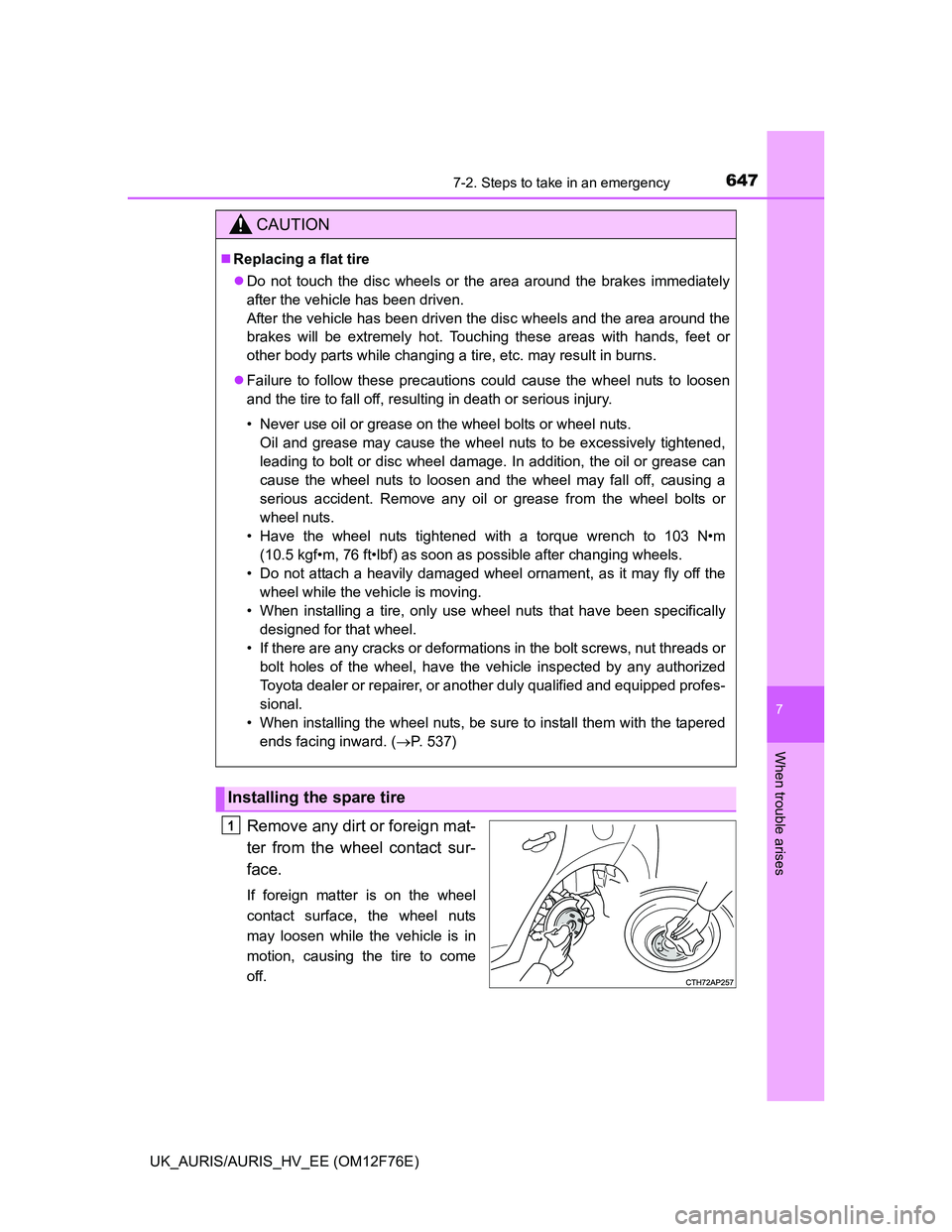
Remove any dirt or foreign mat-
ter from the wheel contact sur-
face.
If foreign matter is on the wheel
contact surface, the wheel nuts
may loosen while the vehicle is in
motion, causing the tire to come
off.
CAUTION
Replacing a flat tire
Do not touch the disc wheels or the area around the brakes immediately
after the vehicle has been driven.
After the vehicle has been driven the disc wheels and the area around the
brakes will be extremely hot. Touching these areas with hands, feet or
other body parts while changing a tire, etc. may result in burns.
Failure to follow these precautions could cause the wheel nuts to loosen
and the tire to fall off, resulting in death or serious injury.
• Never use oil or grease on the wheel bolts or wheel nuts.
Oil and grease may cause the wheel nuts to be excessively tightened,
leading to bolt or disc wheel damage. In addition, the oil or grease can
cause the wheel nuts to loosen and the wheel may fall off, causing a
serious accident. Remove any oil or grease from the wheel bolts or
wheel nuts.
• Have the wheel nuts tightened with a torque wrench to 103 N•m
(10.5 kgf•m, 76 ft•lbf) as soon as possible after changing wheels.
• Do not attach a heavily damaged wheel ornament, as it may fly off the
wheel while the vehicle is moving.
• When installing a tire, only use wheel nuts that have been specifically
designed for that wheel.
• If there are any cracks or deformations in the bolt screws, nut threads or
bolt holes of the wheel, have the vehicle inspected by any authorized
Toyota dealer or repairer, or another duly qualified and equipped profes-
sional.
• When installing the wheel nuts, be sure to install them with the tapered
ends facing inward. (P. 537)
Installing the spare tire
1
Page 648 of 768
6487-2. Steps to take in an emergency
UK_AURIS/AURIS_HV_EE (OM12F76E)
Install the tire and loosely tighten each wheel nut by hand by
approximately the same amount.
When replacing a steel wheel
with a steel wheel (including a
compact spare tire), tighten the
wheel nuts until the tapered
portion comes into loose con-
tact with the disc wheel seat.
When replacing an aluminum
wheel with a steel wheel
(including a compact spare
tire), tighten the wheel nuts until
the tapered portion comes into
loose contact with the disc
wheel seat.
Lower the vehicle.2
Tapered portion
Disc wheel
seat
Tapered portion
Disc wheel seat
3
Vehicles with a compact spare
tireVehicles with a full-size spare
tire
Page 649 of 768

6497-2. Steps to take in an emergency
UK_AURIS/AURIS_HV_EE (OM12F76E)
7
When trouble arises
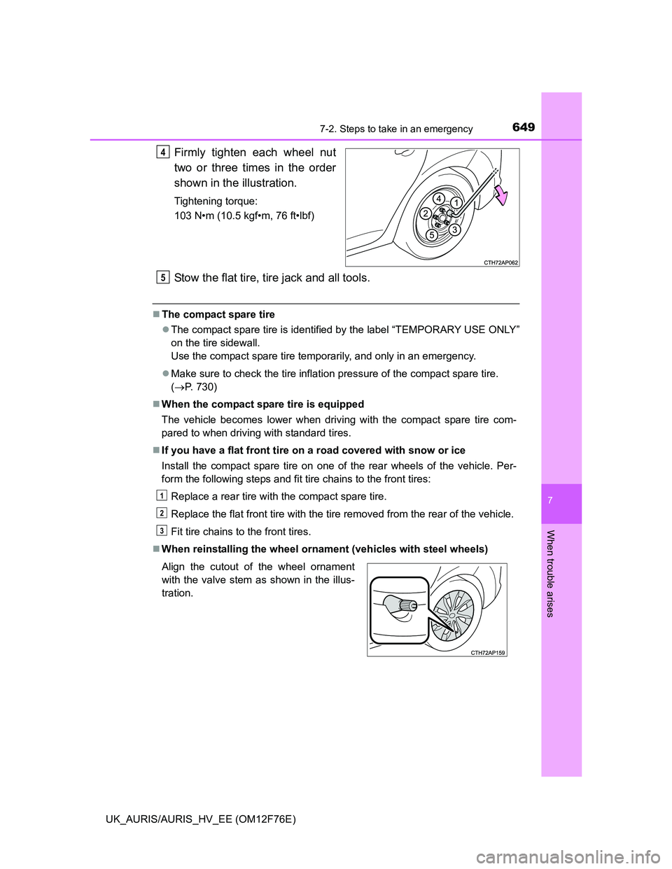
Firmly tighten each wheel nut
two or three times in the order
shown in the illustration.
Tightening torque:
103 N•m (10.5 kgf•m, 76 ft•lbf)
Stow the flat tire, tire jack and all tools.
The compact spare tire
The compact spare tire is identified by the label “TEMPORARY USE ONLY”
on the tire sidewall.
Use the compact spare tire temporarily, and only in an emergency.
Make sure to check the tire inflation pressure of the compact spare tire.
(P. 730)
When the compact spare tire is equipped
The vehicle becomes lower when driving with the compact spare tire com-
pared to when driving with standard tires.
If you have a flat front tire on a road covered with snow or ice
Install the compact spare tire on one of the rear wheels of the vehicle. Per-
form the following steps and fit tire chains to the front tires:
Replace a rear tire with the compact spare tire.
Replace the flat front tire with the tire removed from the rear of the vehicle.
Fit tire chains to the front tires.
When reinstalling the wheel ornament (vehicles with steel wheels)
4
Align the cutout of the wheel ornament
with the valve stem as shown in the illus-
tration.
5
1
2
3
Page 733 of 768
7338-1. Specifications
UK_AURIS/AURIS_HV_EE (OM12F76E)
8
Vehicle specifications
Compact spare tire
When towing a trailer
Add 20.0 kPa (0.2 kgf/cm
2 or bar, 3 psi) to the recommended tire inflation
pressure and drive at speeds below 100 km/h (62 mph).
Tire sizeT125/70D17 98M
Tire inflation pressure
(Recommended cold
tire inflation pressure)
420 kPa (4.2 kgf/cm2 or bar, 60 psi)
Wheel size17 4T
Wheel nut torque103 N•m (10.5 kgf•m, 76 ft•lbf)
Page 762 of 768

762Alphabetical index
UK_AURIS/AURIS_HV_EE (OM12F76E)
Sensor
Automatic headlight
system ................................ 313
Automatic High Beam
system ................................ 319
Inside rear view mirror .......... 215
Intrusion sensor .................... 107
Rain-sensing windshield
wipers ................................. 323
Toyota parking
assist-sensor ...................... 340
Service plug ............................... 84
Shift lever ......... 284, 289, 294, 297
Hybrid transmission .............. 297
If the shift lever cannot
be shifted ............................ 683
If the shift lever cannot
be shifted from P ................ 682
Manual transmission ............. 294
Multidrive............................... 284
Multi-mode manual
transmission ....................... 289
Shift lock system ............. 682, 683
Side airbags ............................... 46
Side mirrors.............................. 216
Adjusting and folding............. 216
Side turn signal lights ............. 305
Replacing light bulbs ............. 567
Turn signal lever ................... 305
Wattage................................. 734Simple-IPA................................ 346
Smart entry & start system ..... 149
Antenna location ................... 151
Entry functions ...................... 149
Starting the engine................ 266
Starting the hybrid system .... 276
Warning message ................. 614
Snow tires ................................ 383
Spare tire .................................. 640
Inflation pressure .................. 733
Storage location .................... 641
Spark plug ................................ 726
Specifications .......................... 712
Speech command system*
Speed limiter ............................ 337
Speedometer .................... 121, 125
Sport mode............................... 285
Steering lock
Column lock release ..... 264, 273
Steering lock system
warning message ............... 625
Steering wheel ......................... 213
Adjustment ............................ 213
Audio switches ...................... 450
Stop & Start cancel switch ..... 363
Stop & Start system ................ 362
Stop & Start system
operation time ............... 123, 129
Stop & Start system total
operation time ............... 123, 129