2013 SUZUKI ERTIGA clock
[x] Cancel search: clockPage 133 of 207

Downloaded from www.Manualslib.com manuals search engine 5-38
OTHER CONTROLS AND EQUIPMENT
60MK0-14E
60MH031
NOTE:
You can also use the cap holder (2) to hold
the fuel filler cap (3) by hooking the groove
(4) when refueling.
To reinstall the fuel filler cap:
1) Turn the cap clockwise until you hear
several clicks.
2) Close the fuel filler door.
Engine Hood
74LHT0533
To open the engine hood:
1) Pull the hood release handle located on
the outboard side of the driver’s side of
the instrument panel. This will disen-
gage the engine hood lock halfway.
WARNING
Fuel is extremely flammable. Do not
smoke when refueling, and make
sure there are no open flames or
sparks in the area.
(2)
(3)(4) (2)
(2)
EXAMPLE
WARNING
If you need to replace the fuel cap,
use a genuine SUZUKI cap. Use of an
improper cap can result in a malfunc-
tion of the fuel system or emission
control system. It may also result in
fuel leakage in the event of an acci-
dent.
EXAMPLE
Page 155 of 207

Downloaded from www.Manualslib.com manuals search engine 7-10
INSPECTION AND MAINTENANCE
60MK0-14E
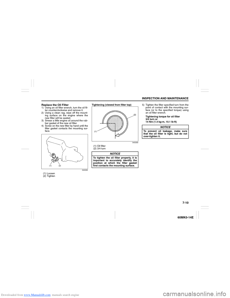
Replace the Oil Filter1) Using an oil filter wrench, turn the oil fil-
ter counterclockwise and remove it.
2) Using a clean rag, wipe off the mount-
ing surface on the engine where the
new filter will be seated.
3) Smear a little engine oil around the rub-
ber gasket of the new oil filter.
4) Screw on the new filter by hand until the
filter gasket contacts the mounting sur-
face.
54G092
(1) Loosen
(2) TightenTightening (viewed from filter top)
54G093
(1) Oil filter
(2) 3/4 turn5) Tighten the filter specified turn from the
point of contact with the mounting sur-
face (or to the specified torque) using
an oil filter wrench.
Tightening torque for oil filter
3/4 turn or
14 Nm (1.4 kg-m, 10.1 lb-ft)
NOTICE
To tighten the oil filter properly, it is
important to accurately identify the
position at which the filter gasket
first contacts the mounting surface.
NOTICE
To prevent oil leakage, make sure
that the oil filter is tight, but do not
over-tighten it.
Page 173 of 207

Downloaded from www.Manualslib.com manuals search engine 7-28
INSPECTION AND MAINTENANCE
60MK0-14E
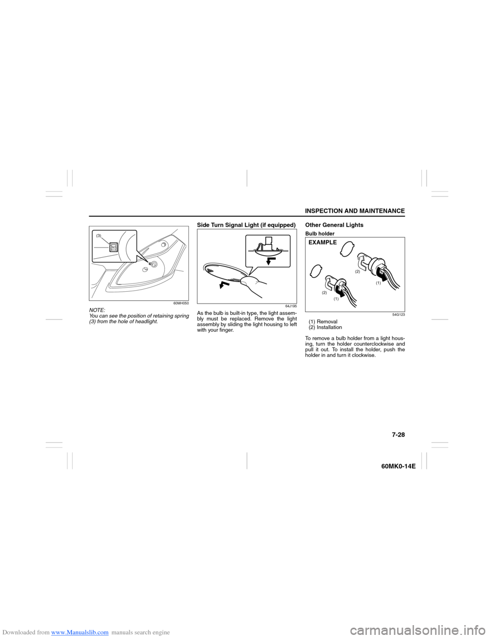
60MH050
NOTE:
You can see the position of retaining spring
(3) from the hole of headlight.
Side Turn Signal Light (if equipped)
64J195
As the bulb is built-in type, the light assem-
bly must be replaced. Remove the light
assembly by sliding the light housing to left
with your finger.
Other General LightsBulb holder
54G123
(1) Removal
(2) Installation
To remove a bulb holder from a light hous-
ing, turn the holder counterclockwise and
pull it out. To install the holder, push the
holder in and turn it clockwise.
(3)
(1)
(1) (2)(2)
EXAMPLE
Page 174 of 207

Downloaded from www.Manualslib.com manuals search engine 7-29INSPECTION AND MAINTENANCE
60MK0-14E
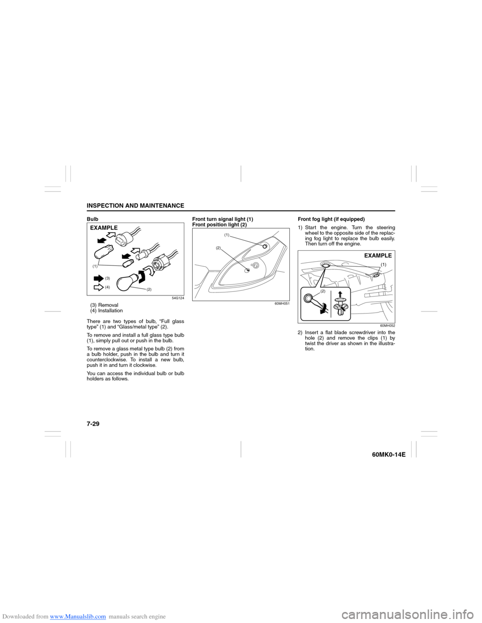
Bulb
54G124
(3) Removal
(4) Installation
There are two types of bulb, “Full glass
type” (1) and “Glass/metal type” (2).
To remove and install a full glass type bulb
(1), simply pull out or push in the bulb.
To remove a glass metal type bulb (2) from
a bulb holder, push in the bulb and turn it
counterclockwise. To install a new bulb,
push it in and turn it clockwise.
You can access the individual bulb or bulb
holders as follows.Front turn signal light (1)
Front position light (2)
60MH051
Front fog light (if equipped)
1) Start the engine. Turn the steering
wheel to the opposite side of the replac-
ing fog light to replace the bulb easily.
Then turn off the engine.
60MH052
2) Insert a flat blade screwdriver into the
hole (2) and remove the clips (1) by
twist the driver as shown in the illustra-
tion.
(1)
(2) (3)
(4)EXAMPLE
(1)
(2)
(1)
(2)
EXAMPLE
Page 175 of 207

Downloaded from www.Manualslib.com manuals search engine 7-30
INSPECTION AND MAINTENANCE
60MK0-14E
80JM071
3) Open the fender cover. Disconnect the
coupler with pushing the lock release.
Turn the bulb holder counterclockwise
and remove it.Rear combination light
(tail, stop, turn signal, etc.)
60MH053
Remove the screw (1). Remove the combi-
nation light (2) by pulling it outside.
License plate light
Since special procedures are required, we
recommend you take your vehicle to your
SUZUKI dealer for bulb replacement.High-mount stop light
80J100
To remove a high-mount stop light housing
the following procedure:
1) Open the tailgate, and remove the nuts
(1) as shown in the illustration.
EXAMPLE
(1)
(1)(2)
(1)
EXAMPLE
Page 182 of 207

Downloaded from www.Manualslib.com manuals search engine 8-1EMERGENCY SERVICE
60MK0-14E
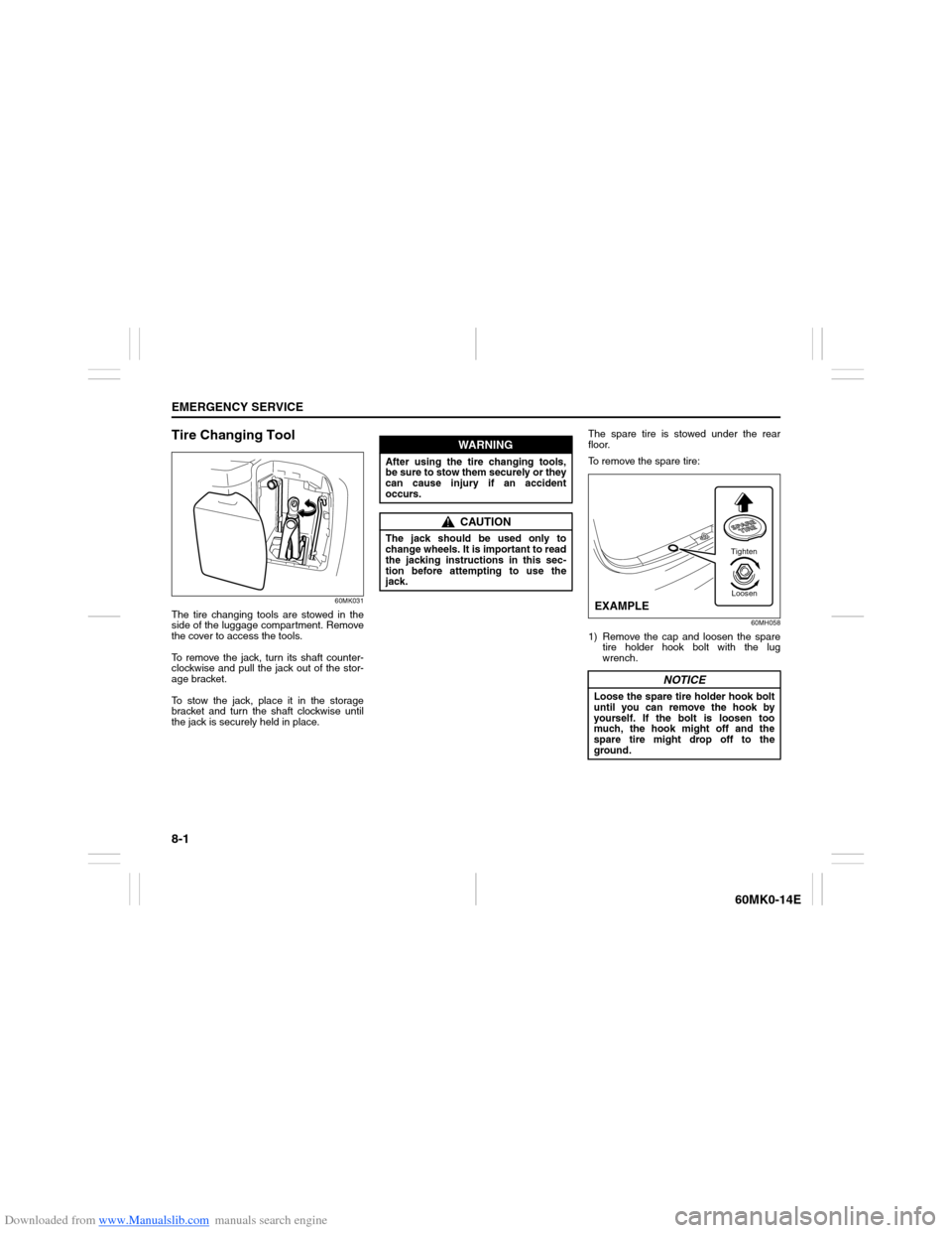
Tire Changing Tool
60MK031
The tire changing tools are stowed in the
side of the luggage compartment. Remove
the cover to access the tools.
To remove the jack, turn its shaft counter-
clockwise and pull the jack out of the stor-
age bracket.
To stow the jack, place it in the storage
bracket and turn the shaft clockwise until
the jack is securely held in place.The spare tire is stowed under the rear
floor.
To remove the spare tire:
60MH058
1) Remove the cap and loosen the spare
tire holder hook bolt with the lug
wrench.
WARNING
After using the tire changing tools,
be sure to stow them securely or they
can cause injury if an accident
occurs.
CAUTION
The jack should be used only to
change wheels. It is important to read
the jacking instructions in this sec-
tion before attempting to use the
jack.
NOTICE
Loose the spare tire holder hook bolt
until you can remove the hook by
yourself. If the bolt is loosen too
much, the hook might off and the
spare tire might drop off to the
ground.
Tighten
Loosen
EXAMPLE
Page 184 of 207

Downloaded from www.Manualslib.com manuals search engine 8-3EMERGENCY SERVICE
60MK0-14E
3) Turn on the hazard warning flasher if
your vehicle is near traffic.
4) Block the front and rear of the wheel
diagonally opposite of the wheel being
lifted.
5) Place the spare wheel near the wheel
being lifted as shown in the illustration
in case that the jack slips.
54G253
63J10060MK032
6) Position the jack at an angle as shown
in the illustration and raise the jack by
turning the jack handle clockwise until
the jack-head groove fits around the
jacking bar beneath the vehicle body.
7) Continue to raise the jack slowly and
smoothly until the tire clears the
ground. Do not raise the vehicle more
than necessary.
To Raise the Vehicle with a Garage Jack
Apply the garage jack to one of the
points indicated below.
Always support the raised vehicle with
jack stands (commercially available) at
the points indicated below.
WARNING
Use the jack only to change wheels
on level, hard ground.
Never jack up the vehicle on an
inclined surface.
Never raise the vehicle with the
jack in a location other than the
specified jacking point (shown in
the illustration) near the wheel to
be changed.
Especially, do not raise the vehicle
with a jack at a part of the torsion
beam which is located under the
vehicle body, between rear wheels.
Make sure that the jack is raised at
least 51 mm (2 inches) before it
contacts the flange. Use of the jack
when it is within 51 mm (2 inches)
of being fully collapsed may result
in failure of the jack.
No person should place any por-
tion of their body under a vehicle
that is supported by a jack.
Never run the engine when the
vehicle is supported by the jack
and never allow passengers to
remain in the vehicle.
Page 203 of 207

Downloaded from www.Manualslib.com manuals search engine 12-1
INDEX
12
60MK0-14E
INDEXSymbols“AIR BAG” Light .................................................................. 2-40Numerics4-Speed Automatic Transaxle ............................................ 3-10AAccelerator Pedal .................................................................. 3-7
Accessory Socket ................................................................ 5-41
Adding Coolant .................................................................... 7-12
Adjusting Seat Position ...................................................... 2-14
Adjusting Seat Position (for 2nd row seats) ..................... 2-16
Adjusting Seatbacks .................................................. 2-15, 2-16
Air Cleaner............................................................................ 7-13
Air Conditioning System .............................................. 5-1, 7-35
All Seat Belts Except Center of 2nd Row Seat.................. 2-23
Anti-Lock Brake System (ABS) .......................................... 3-13
Anti-Lock Brake System (ABS) Warning Light ................. 2-39
Anti-Theft Feature ................................................................ 5-31
Armrest ................................................................................. 5-44
Assist Grips.......................................................................... 5-42
Audio System ......................................................................... 5-7
Automatic Transaxle ........................................................... 3-10
Automatic Transaxle (AT) Fluid.......................................... 7-16
Average fuel consumption......................................... 2-47, 2-49BBattery .................................................................................. 7-22
Bottle holder......................................................................... 5-43
Brake Assist System ........................................................... 3-13
Brake Fluid ........................................................................... 7-17
Brake Pedal ................................................................... 3-7, 7-18Brake System Warning Light .............................................. 2-38
Brakes ................................................................................... 7-17
Braking .................................................................................. 3-12
Brightness Control............................................................... 2-45
Bulb Replacement ................................................................ 7-26
CCatalytic Converter ................................................................ 4-1
CD Player .............................................................................. 5-15
Center Seat Belt of 2nd Row Seat ...................................... 2-24
Central Door Locking System ............................................... 2-3
Changing Engine Oil and Filter............................................. 7-9
Changing Wheels ................................................................... 8-5
Charging Light...................................................................... 2-40
Chassis Serial Number ........................................................ 10-1
Child Restraint Systems ...................................................... 2-27
Child-Proof Locks (rear door) ............................................... 2-3
Clock ..................................................................................... 2-50
Clutch Pedal .................................................................. 3-7, 7-16
Coolant Level Check ............................................................ 7-12
Coolant Replacement .......................................................... 7-12
Corrosion Prevention ............................................................ 9-1
Cup Holder and Storage Area ............................................. 5-43DDaily Inspection Checklist..................................................... 3-1
Door Locks ............................................................................. 2-2
Downshifting maximum allowable speeds .......................... 3-9
Drive Belt ................................................................................ 7-7
Driver’s Seat Belt Reminder ................................................ 2-25
Driver’s Seat Belt Reminder Light ...................................... 2-40
Driving on Hills ....................................................................... 4-3
Driving on Slippery Roads .................................................... 4-4