2013 SUBARU TRIBECA width
[x] Cancel search: widthPage 170 of 420
Gear
position Period of
time multi-
function
button is pressed Function
displayed
R (reverse) Briefly
Rear view display ON/OFF*
More than
3 seconds Help lines indica-
tion ON/OFF
Except
R (reverse) Briefly
Auto-dimming
function ON/OFF*
3to6 seconds Electronic com-
pass display ON/ OFF
6to9seconds Enter the com-
pass zone setting mode
9to12 seconds Enter the com-
pass calibration mode
*: The setting returns to “ON ”as a default
setting every time the ignition switch is turned tothe “ON ”position.
! Rear view image display
When the ignition switch is “ON ”and the
select lever is set to “R ”, the rear view
camera automatically displays the rear
view image behind the vehicle on the
inside mirror.
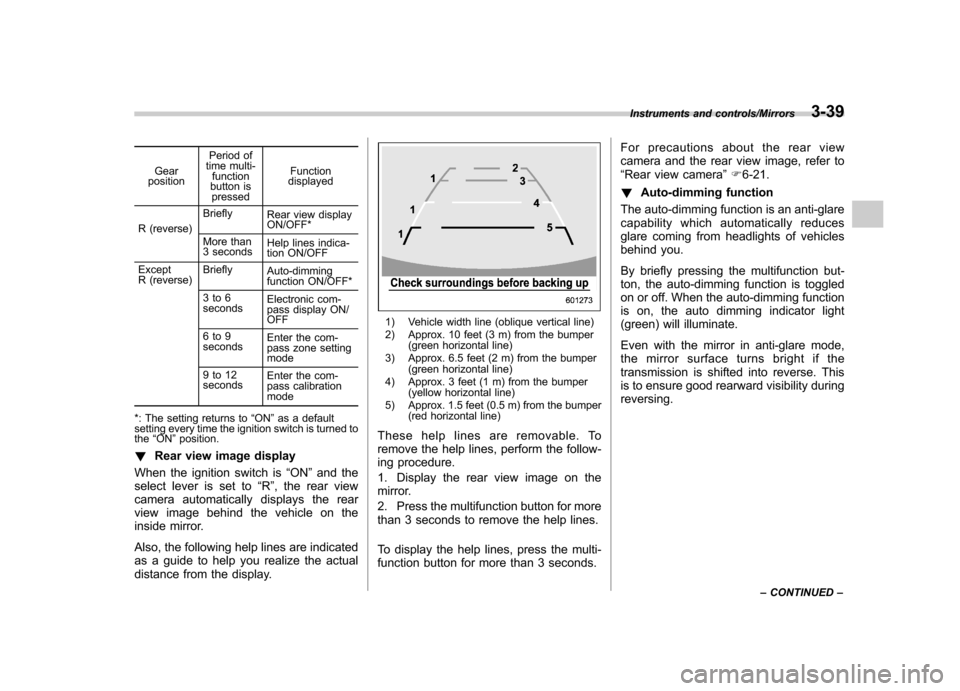
Also, the following help lines are indicated
as a guide to help you realize the actual
distance from the display.
1) Vehicle width line (oblique vertical line)
2) Approx. 10 feet (3 m) from the bumper (green horizontal line)
3) Approx. 6.5 feet (2 m) from the bumper (green horizontal line)
4) Approx. 3 feet (1 m) from the bumper (yellow horizontal line)
5) Approx. 1.5 feet (0.5 m) from the bumper (red horizontal line)
These help lines are removable. To
remove the help lines, perform the follow-
ing procedure.
1. Display the rear view image on the
mirror.
2. Press the multifunction button for more
than 3 seconds to remove the help lines.
To display the help lines, press the multi-
function button for more than 3 seconds. For precautions about the rear view
camera and the rear view image, refer to“
Rear view camera ”F 6-21.
! Auto-dimming function
The auto-dimming function is an anti-glare
capability which automatically reduces
glare coming from headlights of vehicles
behind you.
By briefly pressing the multifunction but-
ton, the auto-dimming function is toggled
on or off. When the auto-dimming function
is on, the auto dimming indicator light
(green) will illuminate.
Even with the mirror in anti-glare mode,
the mirror surface turns bright if the
transmission is shifted into reverse. This
is to ensure good rearward visibility duringreversing.
Instruments and controls/Mirrors3-39
– CONTINUED –
Page 243 of 420
6-24Interior equipment/Rear view camera
Range of view
Image from camera
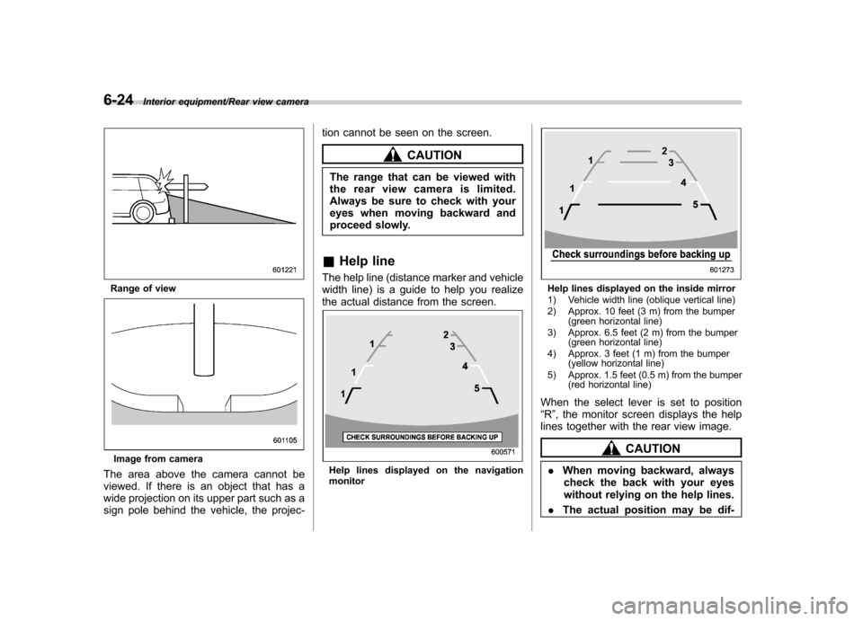
The area above the camera cannot be
viewed. If there is an object that has a
wide projection on its upper part such as a
sign pole behind the vehicle, the projec- tion cannot be seen on the screen.
CAUTION
The range that can be viewed with
the rear view camera is limited.
Always be sure to check with your
eyes when moving backward and
proceed slowly.
& Help line
The help line (distance marker and vehicle
width line) is a guide to help you realize
the actual distance from the screen.
Help lines displayed on the navigation monitor
Help lines displayed on the inside mirror
1) Vehicle width line (oblique vertical line)
2) Approx. 10 feet (3 m) from the bumper (green horizontal line)
3) Approx. 6.5 feet (2 m) from the bumper (green horizontal line)
4) Approx. 3 feet (1 m) from the bumper (yellow horizontal line)
5) Approx. 1.5 feet (0.5 m) from the bumper (red horizontal line)
When the select lever is set to position “ R ”, the monitor screen displays the help
lines together with the rear view image.
CAUTION
. When moving backward, always
check the back with your eyes
without relying on the help lines.
. The actual position may be dif-
Page 283 of 420
8-6Driving tips/On–road and off –road driving
On-road and off-road driving
WARNING
. In a rollover crash, an unbelted
person is significantly more
likely to die than a person wear-
ing a seatbelt. You the driver and
all your passengers should fas-
ten the seatbelts before starting
to drive in order to minimize the
chance of serious injury or death.
. Do not make sharp turns and
quick maneuvers unless abso-
lutely unavoidable. Such actions
are dangerous as you may lose
control, possibly resulting in a
rollover which could cause death
or serious injury.
. Always maintain a safe driving
speed according to the road and
weather conditions in order to
avoid having an accident on a
sharp turn, during sudden brak-
ing or under other similar condi-tions.
. Whenever strong crosswinds are
present, slow down sufficiently
to maintain control of your vehi-
cle. Remember that your vehicle,
with its higher profile and center of gravity, is more likely to be
affected by crosswinds than or-
dinary passenger cars.
. Always use the utmost care in
driving –overconfidence be-
cause you are driving an All-
Wheel Drive model could easily
lead to a serious accident.
Your vehicle is classified as a utility
vehicle. Utility vehicles feature a higher
ground clearance which enables them to
be used for wide applications including off-
road driving. But please keep in mind that
your vehicle is neither a conventional off-
road vehicle nor an all-terrain vehicle. A
higher center of gravity in relation to the
tread width as compared with ordinary
passenger cars makes vehicles of this
type more likely to roll over. In reality, utility
vehicles have a significantly higher roll-
over rate than other types of vehicles. The
high ground clearance of this vehicle is a
real advantage, giving you a better view of
the road and allowing you to anticipate
problems earlier. However, remember that
your utility vehicle is not designed for high-
speed cornering comparable to ordinary
passenger cars and that your vehicle
could roll over if you make a sharp turn
at high speed. If you do take your
SUBARU off-road, certain common sense precautions such as those in the following
list should be taken. .
Make certain that you and all of your
passengers are wearing seatbelts.. Carry some emergency equipment,
such as a towing rope or chain, a shovel,
wheel blocks, first aid kit and cell phone or
citizens band radio. . Drive carefully. Do not take unneces-
sary risks by driving in dangerous areas or
over rough terrain. . Slow down and employ extra caution at
all times. When driving off-road, you will
not have the benefit of marked traffic
lanes, banked curves, traffic signs and
the like. . Do not drive across steep slopes.
Instead, drive either straight up or straight
down the slopes. A vehicle can much
more easily tip over sideways than it can
end over end. Avoid driving straight up or
down slopes that are too steep. . Avoid sharp turning maneuvers, espe-
cially at higher speeds.. Do not grip the inside or spokes of the
steering wheel. A bad bump could jerk the
wheel and injure your hands. Instead drive
with your fingers and thumbs on the
outside of the rim. . If driving through water, such as when
crossing shallow streams, first check the
Page 310 of 420
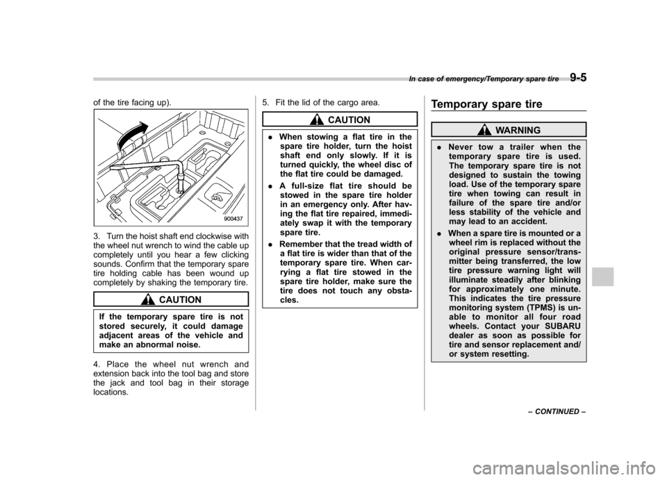
of the tire facing up).
3. Turn the hoist shaft end clockwise with
the wheel nut wrench to wind the cable up
completely until you hear a few clicking
sounds. Confirm that the temporary spare
tire holding cable has been wound up
completely by shaking the temporary tire.
CAUTION
If the temporary spare tire is not
stored securely, it could damage
adjacent areas of the vehicle and
make an abnormal noise.
4. Place the wheel nut wrench and
extension back into the tool bag and store
the jack and tool bag in their storagelocations. 5. Fit the lid of the cargo area.
CAUTION
. When stowing a flat tire in the
spare tire holder, turn the hoist
shaft end only slowly. If it is
turned quickly, the wheel disc of
the flat tire could be damaged.
. A full-size flat tire should be
stowed in the spare tire holder
in an emergency only. After hav-
ing the flat tire repaired, immedi-
ately swap it with the temporary
spare tire.
. Remember that the tread width of
a flat tire is wider than that of the
temporary spare tire. When car-
rying a flat tire stowed in the
spare tire holder, make sure the
tire does not touch any obsta-cles. Temporary spare tire
WARNING
. Never tow a trailer when the
temporary spare tire is used.
The temporary spare tire is not
designed to sustain the towing
load. Use of the temporary spare
tire when towing can result in
failure of the spare tire and/or
less stability of the vehicle and
may lead to an accident.
. When a spare tire is mounted or a
wheel rim is replaced without the
original pressure sensor/trans-
mitter being transferred, the low
tire pressure warning light will
illuminate steadily after blinking
for approximately one minute.
This indicates the tire pressure
monitoring system (TPMS) is un-
able to monitor all four road
wheels. Contact your SUBARU
dealer as soon as possible for
tire and sensor replacement and/
or system resetting.
In case of emergency/Temporary spare tire9-5
– CONTINUED –
Page 315 of 420
9-10In case of emergency/Flat tires
holder.
Refer to“Spare tire ”F 9-2 for its location,
instructions and precautions.
CAUTION
. When stowing a flat tire in the
spare tire holder, turn the hoist
shaft end only slowly. If it is
turned quickly, the wheel disc of
the flat tire could be damaged.
. A full-size flat tire should be
stowed in the spare tire holder
in an emergency only. After hav-
ing the flat tire repaired, immedi-
ately swap it with the temporary
spare tire.
. Remember that the tread width of
a flat tire is wider than that of the
temporary spare tire. When car-
rying a flat tire stowed in the
spare tire holder, make sure the
tire does not touch any obsta-cles.
WARNING
Never place a tire or tire changing
tools in the passenger compartment
after changing wheels. In a sudden
stop or collisions, loose equipment could strike occupants and cause
injury. Store the tire and all tools in
the proper place.
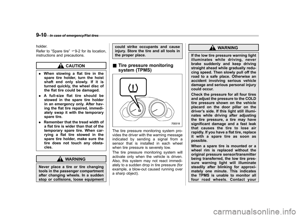
& Tire pressure monitoring
system (TPMS)
The tire pressure monitoring system pro-
vides the driver with the warning message
indicated by sending a signal from a
sensor that is installed in each wheel
when tire pressure is severely low.
The tire pressure monitoring system will
activate only when the vehicle is driven.
Also, this system may not react immedi-
ately to a sudden drop in tire pressure (for
example, a blow-out caused running over
a sharp object).
WARNING
If the low tire pressure warning light
illuminates while driving, never
brake suddenly and keep driving
straight ahead while gradually redu-
cing speed. Then slowly pull off the
road to a safe place. Otherwise an
accident involving serious vehicle
damage and serious personal injury
could occur.
Check the pressure for all four tires
and adjust the pressure to the COLD
tire pressure shown on the vehicle
placard on the door pillar on thedriver ’s side. If this light still illumi-
nates while driving after adjusting
the tire pressure, a tire may have
significant damage and a fast leak
that causes the tire to lose air
rapidly. If you have a flat tire, replace
it with a spare tire as soon as possible.
When a spare tire is mounted or a
wheel rim is replaced without the
original pressure sensor/transmitter
being transferred, the low tire pres-
sure warning light will illuminate
steadily after blinking for approxi-
mately one minute. This indicates
the TPMS is unable to monitor all
four road wheels. Contact your
Page 377 of 420

12-2Specifications/Specifications
Specifications
These specifications are subject to change without notice. &Dimensions
in (mm)
Overall length 191.5 (4,865)
Overall width 73.9 (1,878)
Overall height Without roof rail 66.7 (1,695)
With roof rail 68.1 (1,730)
Wheel base 108.1 (2,745)
Tread Front 62.0 (1,575)
Rear 62.0 (1,575)
Ground clearance 8.3 (211)
& Engine
Engine model EZ36D
(3.6 L, DOHC, non-turbo)
Engine type Horizontally opposed, liquid cooled 6 cylinder, 4 stroke gasoline engine
Displacement cc (cu-in) 3,630 (221.5)
Bore 6Stroke in (mm) 3.6263.58 (92.0 691.0)
Compression ratio 10.5 : 1
Firing order 1
–6 –3–2 –5– 4
Page 393 of 420

13-2Consumer information and Reporting safety defects/For U.S.A.
For U.S.A.
The following information has been
compiled according to Code of
Federal Regulations“Title 49, Part
575 ”. Tire information &
Tire labeling
Many markings (e.g. Tire size, Tire
Identification Number or TIN) are
placed on the sidewall of a tire by
tire manufacturers. These markings
can provide you with useful infor-
mation on the tire. ! Tire size
Your vehicle comes equipped with
P-Metric tire size. It is important to
understand the sizing system in
selecting the proper tire for your
vehicle. Here is a brief review of the
tire sizing system with a breakdown
of its individual elements.
!P Metric
With the P-Metric system, Section
Width is measured in millimeters.
To convert millimeters into inches,
divide by 25.4. The Aspect Ratio
(Section Height divided by Section
Width) helps provide more dimen-
sional information about the tiresize. Example:
(1) P = Certain tire type used on
light duty vehicles such as passen-
ger cars
(2) Section Width in millimeters
(3) Aspect Ratio (= section height 7
section width).
(4) R = Radial Construction
(5) Rim diameter in inches
! Load and Speed Rating De-
scriptions
The load and speed rating descrip-
tions will appear following the size designation.
They provide two important facts
about the tire. First, the number
designation is its load index. Sec-
ond, the letter designation indicates
the tire ’s speed rating.
Page 398 of 420

.Measuring rim
The rim on which a tire is fitted for
physical dimension requirements. . Normal occupant weight
150 lbs (68 kg) times the number of
occupants specified in the second
column of Table 1 that is appended
to the end of this section. . Occupant distribution
Distribution of occupants in a vehi-
cle as specified in the third column
of Table 1 that is appended to the
end of this section. . Open splice
Any parting at any junction of tread,
sidewall, or innerliner that extends
to cord material. . Outer diameter
The overall diameter of an inflated
new tire.. Overall width
The linear distance between the
exteriors of the sidewalls of an
inflated tire, including elevations
due to labeling, decorations, or
protective bands or ribs. .
Passenger car tire
A tire intended for use on passen-
ger cars, multipurpose passenger
vehicles, and trucks, that have a
gross vehicle weight rating (GVWR)
of 10,000 lbs (4,535 kg) or less. . Ply
A layer of rubber-coated parallel cords.. Ply separation
A parting of rubber compound
between adjacent plies.. Pneumatic tire
A mechanical device made of rub-
ber, chemicals, fabric and steel or
other materials, that, when
mounted on an automotive wheel,
provides the traction and contains
the gas or fluid that sustains theload. . Production options weight
The combined weight of those
installed regular production options
weighing over 5.1 lbs (2.3 kg) in
excess of those standard items
which they replace, not previously
considered in curb weight or acces- sory weight, including heavy duty
brakes, ride levelers, roof rack,
heavy duty battery, and special trim. .
Radial ply tire
A pneumatic tire in which the ply
cords that extend to the beads are
laid at substantially 90 degrees to
the centerline of the tread. . Recommended inflation pres-
sure
The cold inflation pressure recom-
mended by a vehicle manufacturer. . Reinforced tire
A tire designed to operate at higher
loads and at higher inflation pres-
sures than the corresponding stan-
dard tire. . Rim
A metal support for a tire or a tire
and tube assembly upon which the
tire beads are seated. . Rim diameter
Nominal diameter of the bead seat. . Rim size designation
Rim diameter and width.
Consumer information and Reporting safety defects/Tire information13-7
– CONTINUED –