2013 SUBARU TRIBECA cooling
[x] Cancel search: coolingPage 176 of 420

Ventilator.............................................................. 4-2
Airflow ................................................................ 4-2
Ventilator ............................................................ 4-4
Automatic climate control system ..................... 4-5
Control panel ...................................................... 4-5
Rear air conditioner ............................................. 4-9
Temperature sensors ........................................... 4-9
Operating tips for heater and air conditioner ....................................................... 4-10
Cleaning ventilator grille ..................................... 4-10
Efficient cooling after parking in direct sunlight ........................................................... 4-10 Lubrication oil circulation in the refrigerant
circuit .............................................................. 4-10
Checking air conditioning system before summer season ............................................................ 4-10
Cooling and dehumidifying in high humidity and low temperature weather conditions ................. 4-10
Air conditioner compressor shut-off when engine is heavily loaded .............................................. 4-11
Refrigerant for your climate control system ... ..... 4-11
Air filtration system ........................................... 4-11
Replacing the air filter ........................................ 4-11Climate control
4
Page 181 of 420

4-6Climate control/Automatic climate control system
!OFF button
The Automatic Climate Control system
turns off (the air conditioner compressor
and fan turn off) when the “OFF ”button is
pressed.
When the “OFF ”button is pressed, the
outside air introduction mode (air inlet
selection OFF) is automatically selected. !
Temperature control dialDriver ’s side
Passenger ’s side
It is possible to make separate tempera-
ture settings for the driver ’ssideand
passenger ’s side. Each temperature setting is shown on the display. With the
dial set at your desired temperature, the
system automatically adjusts the tempera-
ture of air supplied from the outlets such
that the desired temperature is achieved
and maintained.
Turning the dial counterclockwise and
releasing it reduces the temperature by1
8F (0.5 8C). Turning the dial clockwise
and releasing it increases the temperature
by 1 8F (0.5 8C). Holding the dial in either
turned position causes the temperature to
change continuously.
With the minimum temperature set, the
system gives maximum cooling perfor-
mance. With the maximum temperature
set, the system gives maximum heatingperformance.
Page 183 of 420

4-8Climate control/Automatic climate control system
NOTE
For efficient defogging or dehumidify-
ing in cold weather, turn on the air
conditioner. However, if the ambient
temperature decreases to approxi-
mately 328F(0 8C), the air conditioner
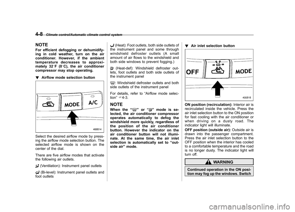
compressor may stop operating. ! Airflow mode selection button
Select the desired airflow mode by press-
ing the airflow mode selection button. The
selected airflow mode is shown on the
center of the dial.
There are five airflow modes that activate
the following air outlets.
(Ventilation): Instrument panel outlets
(Bi-level): Instrument panel outlets and
foot outlets
(Heat): Foot outlets, both side outlets of
the instrument panel and some through
windshield defroster outlets (A small
amount of air flows to the windshield and
both side windows to prevent fogging.)
(Heat-def): Windshield defroster out-
lets, foot outlets and both side outlets of
the instrument panel
: Windshield defroster outlets and both
side outlets of the instrument panel
For details, refer to “Airflow mode selec-
tion ”F 4-3.
NOTE
When the “
”or “”mode is se-
lected, the air conditioner compressor
operates automatically to defog the
windshield more quickly, regardless of
the position of the air conditioner
button. However the indicator on the
air conditioner button will not illumi-
nate. At the same time, the air inlet
selection is automatically set to “out-
side air ”mode. !
Air inlet selection button
ON position (recirculation): Interior air is
recirculated inside the vehicle. Press the
air inlet selection button to the ON position
for fast cooling with the air conditioner or
when driving on a dusty road. The
indicator light will illuminate.
OFF position (outside air): Outside air is
drawn into the passenger compartment.
Press the air inlet selection button to the
OFF position when the interior has cooled
to a comfortable temperature and the road
is no longer dusty. The indicator light will
turn off.
WARNING
Continued operation in the ON posi-
tion may fog up the windows. Switch
Page 185 of 420

4-10Climate control/Operating tips for heater and air conditioner
–Do not cover the sensors.
The sensors are located as follows. – Solar sensor: beside windshield
defroster grille– Interior air temperature sensor: on the
side of the driver-side part of the center panel – Outside temperature sensor: behind
front grille Operating tips for heater and
air conditioner &
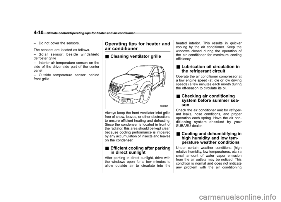
Cleaning ventilator grille
Always keep the front ventilator inlet grille
free of snow, leaves, or other obstructions
to ensure efficient heating and defrosting.
Since the condenser is located in front of
the radiator, this area should be kept clean
because cooling performance is impaired
by any accumulation of insects and leaves
on the condenser. &Efficient cooling after parking
in direct sunlight
After parking in direct sunlight, drive with
the windows open for a few minutes to
allow outside air to circulate into the heated interior. This results in quicker
cooling by the air conditioner. Keep the
windows closed during the operation of
the air conditioner for maximum cooling
efficiency. &
Lubrication oil circulation in
the refrigerant circuit
Operate the air conditioner compressor at
a low engine speed (at idle or low driving
speeds) a few minutes each month during
the off-season to circulate its oil. & Checking air conditioning
system before summer sea-son
Check the air conditioner unit for refriger-
ant leaks, hose conditions, and proper
operation each spring. Have the air con-
ditioning system checked by your
SUBARU dealer. & Cooling and dehumidifying in
high humidity and low tem-
perature weather conditions
Under certain weather conditions (high
relative humidity, low temperatures, etc.) a
small amount of water vapor emission
from the air outlets may be noticed. This
condition is normal and does not indicate
any problem with the air conditioning
Page 246 of 420

Fuel...................................................................... 7-2
Fuel requirements ............................................... 7-2
Fuel filler lid and cap ........................................... 7-3
State emission testing (U.S. only) ...................... 7-5
Preparing to drive ............................................... 7-7
Starting the engine .............................................. 7-7
Stopping the engine ............................................ 7-8
Remote engine start system (dealer option) ..... 7-8
Starting your vehicle ........................................... 7-9
Remote start safety features ................................ 7-9
Entering the vehicle while it is running via remote start .................................................................. 7-9
Entering the vehicle following remote engine start shutdown .......................................................... 7-9
Pre-heating or pre-cooling the interior of the vehicle ............................................................. 7-10
Service mode ..................................................... 7-10
Remote engine start transmitter programming and programmable feature option ..................... 7-10
System maintenance .......................................... 7-11
Automatic transmission ..................................... 7-12
Select lever ........................................................ 7-13
Shift lock function .............................................. 7-14
Selection of manual mode .................................. 7-16
Driving tips ........................................................ 7-17
SPORT mode ..................................................... 7-18 Power steering
................................................... 7-18
Braking ............................................................... 7-19
Braking tips ....................................................... 7-19
Brake system .................................................... 7-19
Disc brake pad wear warning indicators ............. 7-20
ABS (Anti-lock Brake System) .......................... 7-20
ABS system self-check ...................................... 7-21
ABS warning light .............................................. 7-21
Electronic Brake Force Distribution (EBD) system ............................................................. 7-22
Steps to take if EBD system malfunctions ..... ..... 7-22
Vehicle Dynamics Control system .................... 7-23
Vehicle Dynamics Control system monitor..... ..... 7-25
Traction Control system OFF switch ................... 7-25
Tire pressure monitoring system (TPMS) ........ 7-27
Parking your vehicle ......................................... 7-28
Parking brake .................................................... 7-28
Parking tips ....................................................... 7-29
Cruise control .................................................... 7-29
To set cruise control .......................................... 7-30
To temporarily cancel the cruise control ............. 7-31
To turn off the cruise control .............................. 7-31
To change the cruising speed .. .......................... 7-31
Cruise control indicator light .............................. 7-32
Cruise control set indicator light ........................ 7-32
Starting and operating
7
Page 255 of 420

7-10Starting and operating/Remote engine start system (dealer option)
transmitter within a few seconds immedi-
ately following remote engine start shut-down. &Pre-heating or pre-cooling
the interior of the vehicle
Before exiting the vehicle, set the tem-
perature controls to the desired setting
and operation. After the system starts the
vehicle, the heater or air-conditioning will
activate and heat or cool the interior to
your setting. & Service mode
In service mode, the remote start function
is temporarily disabled to prevent the
system from unexpectedly starting the
engine while being serviced. ! To engage the service mode
Turn the ignition switch to the “ON ”
position, depress and hold the brake pedal
then, press and release the “
”button on
the remote engine start transmitter three
times. The system will pause for 1 second
and then flash the parking lights and honk
the horn three times indicating that the
system is in service mode. When attempt-
ing to activate the remote start system
while in service mode, the parking lights
will flash and the horn will honk two times
and will not start. !
To disengage the service mode
Turn the ignition switch to the “ON ”
position, depress and hold the brake
pedal, then press and release the “
”
button on the remote engine start trans-
mitter three times. The system will pause
for 1 second and flash the parking lights
one time indicating that the system has
exited service mode. NOTE
When taking your vehicle in for service,
it is recommended that you inform the
service personnel that your vehicle is
equipped with a remote engine startsystem. & Remote engine start trans-
mitter programming and pro-
grammable feature option
New transmitters can be programmed to
the remote engine start system in the
event that remote engine start transmitters
are lost, stolen or damaged. The remote
engine start system also has one pro-
grammable feature that can be adjusted
for user preference.
The remote engine start system can be
programmed to either make an audible
horn chirp upon remote start activation or
not. Remote engine start transmitter pro-
gramming and feature programming can be adjusted using the following procedure.
1. Open the driver
’s door (the driver ’s
door must remain opened throughout the
entire process).
2. Insert the key into the vehicle ’s ignition
switch and turn to the “ON ”position.
3. Locate the small black programming
button behind the fuse box cover, on the
driver ’s side left under the dashboard
panel.
4. Press and hold the black programming
button for 10 to 15 seconds. The horn will
honk and the parking lights will flash three
times to indicate that the system has
entered programming mode. At this point
you can perform either action (step 5 or
step 6).
5. To program a remote transmitter:
press and release the “
”button on each
transmitter. The horn will honk and the
parking lights will flash one time to indicate
a successful transmitter learn each timethe “
”button is pressed. You can
program up to eight transmitters.
6. To toggle the Horn Confirmation chirps
ON/OFF: press and release the brake to
toggle the feature. The horn will chirp and
the parking lights will flash one time to
indicate Confirmation Horn Chirps are“ OFF ”. The horn will honk and the parking
lights will flash 2 times to indicate Con-
firmation Horn Chirps are “ON ”. Depres-
Page 296 of 420

has safety chains and that each
chain will hold the trailer’s max-
imum gross weight. Towing trai-
lers without safety chains could
create a traffic safety hazard if
the trailer separates from the
hitch due to coupling damage or
hitch ball damage.
. Be sure to check the hitch pin
and safety pin for positive lock-
ing placement before towing a
trailer. If the ball mount comes off
the hitch receiver, the trailer
could get loose and create a
traffic safety hazard.
. Use only the ball mount supplied
with this hitch. Use the hitch only
as a weight carrying hitch. Do not
use with any type of weight
distributing hitch.
The maximum gross trailer weight and
maximum gross tongue weight are indi-
cated in the following table. Maximum
gross trailer weight
Maximum
gross tongue weight
Vehicle with-
out cooling kit 2,000 lbs
(906 kg) 200 lbs
(90 kg)
Vehicle with
cooling kit 3,500 lbs
(1,587 kg) 350 lbs
(158 kg)
When you tow a trailer, follow the instruc-
tions in “Trailer towing ”F 8-21.
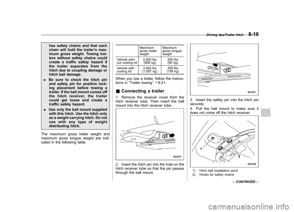
& Connecting a trailer
1. Remove the receiver cover from the
hitch receiver tube. Then insert the ball
mount into the hitch receiver tube.
2. Insert the hitch pin into the hole on the
hitch receiver tube so that the pin passes
through the ball mount.
3. Insert the safety pin into the hitch pin
securely.
4. Pull the ball mount to make sure it
does not come off the hitch receiver.
1) Hitch ball installation point
2) Hooks for safety chains
Driving tips/Trailer hitch8-19
– CONTINUED –
Page 299 of 420

8-22Driving tips/Trailer towing
Vehicle without cooling kitConditions Maximum total trailer weight
When towing a trailer without brakes. 1,000 lbs (453 kg)
When towing a trailer with brakes. 2,000 lbs (906 kg)
When towing a trailer on a long uphill grade
continuously for over 5 miles (8 km) with an
outside temperature of 104 8F (40 8C) or above. 1,000 lbs (453 kg)
Vehicle with cooling kit Conditions Maximum total trailer weight
When towing a trailer without brakes. 1,000 lbs (453 kg)
When towing a trailer with brakes. 3,500 lbs (1,587 kg)
When towing a trailer on a long uphill grade
continuously for over 5 miles (8 km) with an
outside temperature of 104 8F (40 8C) or above. 1,750 lbs (794 kg) !
Gross Vehicle Weight (GVW) and
Gross Vehicle Weight Rating(GVWR)
Gross Vehicle Weight
The Gross Vehicle Weight (GVW) must
never exceed the Gross Vehicle Weight
Rating (GVWR).
Gross Vehicle Weight (GVW) is the
combined total of the weight of the vehicle,
driver, passengers, luggage, trailer hitch,
trailer tongue load and any other optional
equipment installed on your vehicle.
Therefore, the GVW changes depending
on the situation. Determine the GVW each
time before going on a trip by putting your
vehicle and trailer on a vehicle scale.
GVWR is shown on the certification label
located on the driver ’s door of your
vehicle.